dashboard MAZDA 6 2002 Workshop Manual Suplement
[x] Cancel search | Manufacturer: MAZDA, Model Year: 2002, Model line: 6, Model: MAZDA 6 2002Pages: 909, PDF Size: 17.16 MB
Page 414 of 909

J2–12
SHIFT MECHANISM
SHIFT MECHANISM REMOVAL/INSTALLATIONA6E5214460102011. Remove the battery and battery tray.
2. Remove the air cleaner component. (See F2–36 INTAKE-AIR SYSTEM REMOVAL/INSTALLATION.)
3. Remove the dashboard compleat. (See Section S.)
4. Remove the SAS control module. (See Section T.)
5. Remove the climate control unit. (See Section U.)
6. Remove the rear heat duct. (See Section U.)
7. Remove in the order indicated in the table.
8. Install in the reverse order of removal.
9. After installation, verify that the shift lever can be shifted smoothly into each position.
.
SHIFT MECHANISM
7
5
A
A
4
3
3
6
6.86—9.8
{70—99 kgf·cm, 61—85 in·lbf}
15.68—22.54
{1.599—2.298,
11.57—16.62} 7.8—10.8
{80—110 kgf·cm,
69.5—95.4 in·lbf}
1
2
N·m {kgf·m, ft·lbf}
15.68—22.54
{1.599—2.298,
11.57—16.62}
A6E5214W001
1 Shift lever knob
2 Boot panel
3 Clip
4 Seal plate5 Select cable
(See J2–13 Select Cable Installation Note)
6 Shift cable
7 Sift lever component
Page 532 of 909

AUTOMATIC TRANSAXLE SHIFT MECHANISM
K2–117
K2
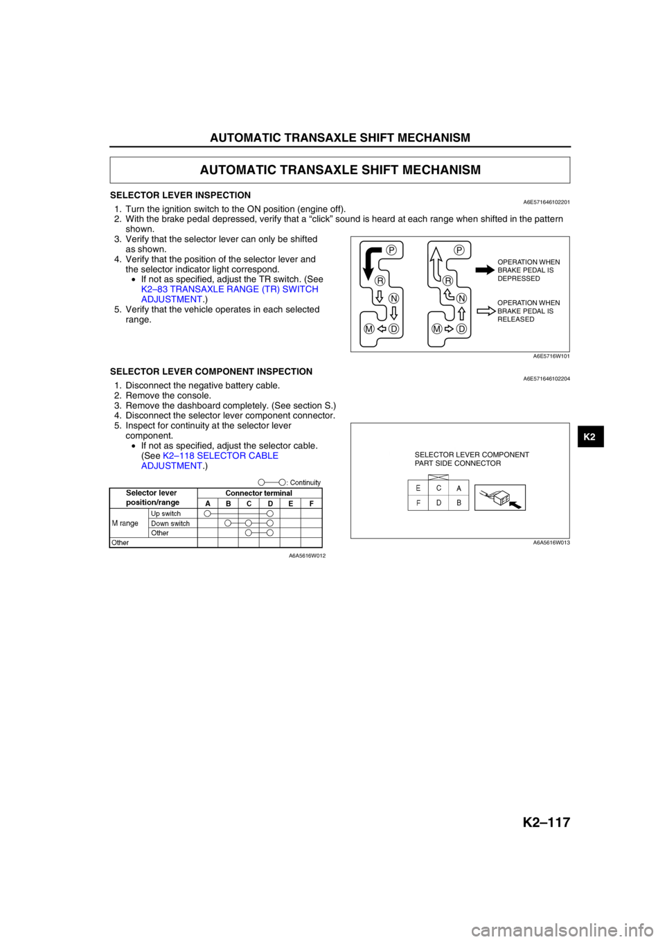
SELECTOR LEVER INSPECTIONA6E5716461022011. Turn the ignition switch to the ON position (engine off).
2. With the brake pedal depressed, verify that a “click” sound is heard at each range when shifted in the pattern
shown.
3. Verify that the selector lever can only be shifted
as shown.
4. Verify that the position of the selector lever and
the selector indicator light correspond.
•If not as specified, adjust the TR switch. (See
K2–83 TRANSAXLE RANGE (TR) SWITCH
ADJUSTMENT.)
5. Verify that the vehicle operates in each selected
range.
End Of SieSELECTOR LEVER COMPONENT INSPECTIONA6E5716461022041. Disconnect the negative battery cable.
2. Remove the console.
3. Remove the dashboard completely. (See section S.)
4. Disconnect the selector lever component connector.
5. Inspect for continuity at the selector lever
component.
•If not as specified, adjust the selector cable.
(See K2–118 SELECTOR CABLE
ADJUSTMENT.)
End Of Sie
AUTOMATIC TRANSAXLE SHIFT MECHANISM
P
R
N
DM
P
R
N
DM
OPERATION WHEN
BRAKE PEDAL IS
DEPRESSED
OPERATION WHEN
BRAKE PEDAL IS
RELEASED
A6E5716W101
SELECTOR LEVER COMPONENT
PART SIDE CONNECTOR
A6A5616W013
A6A5616W012
Page 534 of 909

AUTOMATIC TRANSAXLE SHIFT MECHANISM
K2–119
K2
SELECTOR LEVER REMOVAL/INSTALLATIONA6E5716461022021. Disconnect the negative battery cable.
2. Remove the battery and battery tray.
3. Remove the air cleaner compornent. (See Section F.)
4. Remove the console.
5. Remove the dashboard compleat. (See Section S.)
6. Remove the SAS control module. (See Section T.)
7. Remove the climate control unit. (See Section U.)
8. Remove the rear heat duct. (See Section U.)
9. Remove in the order shown in the figure.
10. Install in the reverse order of removal.
.
1
2
A
A
B
15.68—22.5
{1.60—2.29, 11.6—16.5}
B6.86—9.8 N·m
{70—99 kgf·cm, 61—86 in·lbf}
N·m {kgf·m, ft·lbf}
A6E5716W104
1 Selector cable
(See K2–120 Selector Cable Removal Note.)
(See K2–120 Selector Cable Installation Note.)2Selector lever
Page 873 of 909

U–10
BASIC SYSTEM
A/C UNIT REMOVAL/INSTALLATIONA6E8516611302011. Disconnect the negative battery cable.
2. Discharge the refrigerant from the system.
3. Drain the engine coolant.
4. Remove the dashboard.
5. Remove the theft-deterrent control module.
Caution
•If moisture or foreign material enters the refrigeration cycle, cooling ability will be lowered and
abnormal noise will occur. Always immediately plug open fittings after removing any refrigeration
cycle parts to keep moisture or foreign material out of the cycle.
6. Remove in the order indicated in the table. Do not allow compressor oil to spill.
.
BASIC SYSTEM
1
L.H.D.R.H.D.
3
2
R
R
N·m {kgf·cm, in·lbf} 6.86—9.80
{70.0—99.9,
60.8—86.7}
R
R
3
2
1
4
A6E85162001
1 Heater hose
2 Cooler pipe No.4 (L.H.D.) or cooler pipe No.5
(R.H.D.)
(See U–13 REFRIGERANT LINES REMOVAL/
INSTALLATION) (R.H.D.)
(See U–13 REFRIGERANT LINES REMOVAL/
INSTALLATION)3 Cooler pipe No.3
(See U–13 REFRIGERANT LINES REMOVAL/
INSTALLATION) (R.H.D.)
(See U–13 REFRIGERANT LINES REMOVAL/
INSTALLATION)
4A/C unit
(See U–11 A/C Unit Installation Note)