oil dipstick MAZDA 6 2002 Workshop Manual Suplement
[x] Cancel search | Manufacturer: MAZDA, Model Year: 2002, Model line: 6, Model: MAZDA 6 2002Pages: 909, PDF Size: 17.16 MB
Page 66 of 909

D–2
OUTLINE
OUTLINE OF CONSTRUCTIONA6E330202000201•The construction and the operation of the oil cooler and the oil filter for the new Mazda6 (GG, GY) MZR-CD (RF
Turbo) engine model is the same as the current Mazda MPV (LW) MZR-CD (RF Turbo) engine model. (See
Mazda MPV Workshop Manual Supplement 1737-1*-02D.)
•The construction and the operation of the lubrication system except for the oil cooler and oil filter for the new
Mazda6 (GG, GY) MZR-CD (RF Turbo) engine model is the same as the current Mazda 626, 626 Station
Wagon (GF, GW) RF Turbo engine model. (European specs.) (See Mazda 626, 626 Station Wagon RF Turbo
Workshop Manual Supplement 1614-10-98D.)
•The construction and the operation of the lubrication system for the new Mazda6 (GG, GY) L8, LF, and L3
engine models is the same as the current Mazda6 (GG) engine model L8, LF, and L3 engine models. (See
Mazda6 Training Manual 3359-1*-02C, Mazda6 Workshop Manual 1730-1*-02C.)
End Of Sie
SPECIFICATIONSA6E330202000202Gasoline engine
* : Always verify the oil level with the dipsticks since the engine oil capacity differs according to dipstick
specifications. (See Mazda6 Workshop Manual 1730-1*-02C Section D.)
Recommended Engine Oil (Gasoline Engine)
•The maintenance intervals on the scheduled maintenance table (See GI–8 SCHEDULED MAINTENANCE
TABLE) can only be supported with the use of following oils.
OUTLINE
ItemSpecification
New
Mazda6
(GG, GY)Current
Mazda6
(GG)New
Mazda6
(GG, GY)Current
Mazda6
(GG)New
Mazda6
(GG, GY)Current
Mazda6
(GG)
L8 LF L3*
Lubrication system Force-fed type
Oil coolerWater-cooled
Oil pressure
(approximate quantity)
[oil temperature: 100°C
{212°F}](kPa {kgf/cm
2, psi})
min [rpm]234—521
{2.39—5.31, 33.9—75.5}
[3,000]395—649
{4.03—6.61,
57.3—94.1}
[3,000]
Oil pumpType Trochoid gear type
Relief pressure
(approximate
quantity) (kPa {kgf/cm
2,
psi})500—600
{5.09—6.11, 72.6—87.0}
Oil filterType Full-flow, Paper element
Bypass pressure
(approximate
quantity)(kPa kgf/cm
2, psi})80—120
{0.9—1.2, 12.8—17.0}
Oil capacity
(approximate
quantity)Total
(dry engine)(L {US qt, lmp qt}) 4.6 {4.8, 4.0} Dipstick A: 4.2 {4.4, 3.7}
Dipstick B: 5.1 {5.4, 4.5}
Oil replacement (L {US qt, lmp qt}) 3.9 {4.0, 3.4} Dipstick A: 3.1 {3.3, 2.7}
Dipstick B: 4.0 {4.2, 3.5}
Oil and oil filter
replacement(L {US qt, lmp qt}) 4.3 {4.5, 3.8} Dipstick A: 3.5 {3.7, 3.1}
Dipstick B: 4.4 {4.6, 3.9}
ItemSpecification
New Mazda6
(GG, GY), Current Mazda6
(GG)New Mazda6
(GG, GY), Current Mazda6
(GG)
L8, LF, L3
Engine oil GradeAPI SL
ACEA A3
Viscosity (SAE) 5W-30, 10W-40 5W-20
RemarksMazda genuine Dexelia oil e.g. —
Page 72 of 909
D–8
ENGINE OIL
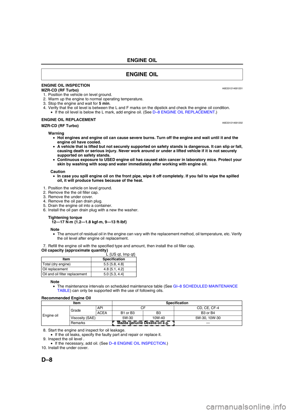
ENGINE OIL INSPECTIONA6E331214001201MZR-CD (RF Turbo)
1. Position the vehicle on level ground.
2. Warm up the engine to normal operating temperature.
3. Stop the engine and wait for 5 min.
4. Verify that the oil level is between the L and F marks on the dipstick and check the engine oil condition.
•If the oil level is below the L mark, add engine oil. (See D–8 ENGINE OIL REPLACEMENT.)
End Of SieENGINE OIL REPLACEMENTA6E331214001202MZR-CD (RF Turbo)
Warning
•Hot engines and engine oil can cause severe burns. Turn off the engine and wait until it and the
engine oil have cooled.
•A vehicle that is lifted but not securely supported on safety stands is dangerous. It can slip or fall,
causing death or serious injury. Never work around or under a lifted vehicle if it is not securely
supported on safety stands.
•Continuous exposure to USED engine oil has caused skin cancer in laboratory mice. Protect your
skin by washing with soap and water immediately after working with engine oil.
Caution
•In case you spill engine oil on the front pipe, wipe it off completely. If you fail to wipe the spilled
oil, it will produce fumes because of the heat.
1. Position the vehicle on level ground.
2. Remove the the oil filler cap.
3. Remove the under cover.
4. Remove the oil pan drain plug.
5. Drain the engine oil into a container.
6. Install the oil pan drain plug with a new the washer.
Tightening torque
12—17 N·m {1.2—1.8 kgf·m, 9—13 ft·lbf}
Note
•The amount of residual oil in the engine can vary with the replacement method, oil temperature, etc. Verify
the oil level after engine oil replacement.
7. Refill the engine oil with the specified type and amount, then install the oil filler cap.
Oil capacity (approximate quantity)
L {US qt, Imp qt}
Note
•The maintenance intervals on scheduled maintenance table (See GI–8 SCHEDULED MAINTENANCE
TABLE) can only be supported with the use of following oils.
Recommended Engine Oil
8. Start the engine and inspect for oil leakage.
•If the oil leaks, specify the faulty part and repair or replace it.
9. Inspect the oil level .
•If the necessary, add oil. (See D–8 ENGINE OIL INSPECTION.)
10. Install the under cover.
End Of Sie
ENGINE OIL
Item Specification
Total (dry engine) 5.5 {5.8, 4.8}
Oil replacement 4.8 {5.1, 4.2}
Oil and oil filter replacement 5.0 {5.3, 4.4}
Item Specification
Engine oil GradeAPI CF CD, CE, CF-4
ACEA B1 or B3 B3 B3 or B4
Viscosity (SAE) 5W-30 10W-40 5W-30, 10W-30
RemarksMazda genuine Dexelia oil e.g. —
Page 146 of 909
F1–58
TROUBLESHOOTING
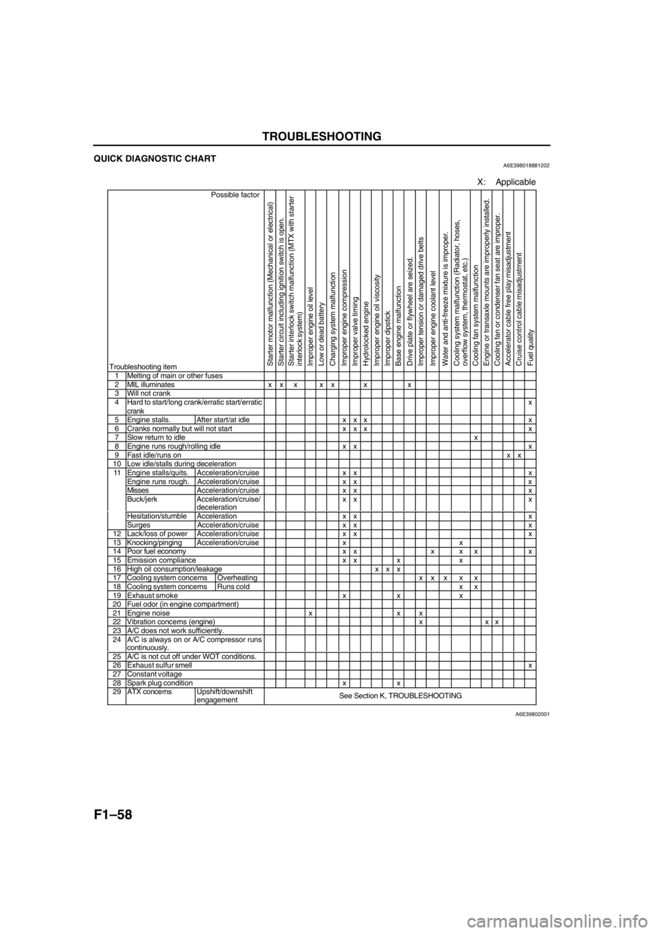
QUICK DIAGNOSTIC CHARTA6E398018881202
X: Applicable
Possible factor
Troubleshooting item
Starter motor malfunction (Mechanical or electrical)
Starter circuit including ignition switch is open.
Starter interlock switch malfunction (MTX with starter
interlock system)
Improper engine oil level
Low or dead battery
Charging system malfunction
Improper engine compression
Improper valve timing
Hydrolocked engine
Improper engine oil viscosity
Improper dipstick
Base engine malfunction
Drive plate or flywheel are seized.
Improper tension or damaged drive belts
Improper engine coolant level
Water and anti-freeze mixture is improper.
Cooling system malfunction (Radiator, hoses,
overflow system, thermostat, etc.)
Cooling fan system malfunction
Engine or transaxle mounts are improperly installed.
Cooling fan or condenser fan seat are improper.
Accelerator cable free play misadjustment
Cruise control cable misadjustment
Fuel quality
1 Melting of main or other fuses2 MIL illuminates x x x x x x x3 Will not crank4 Hard to start/long crank/erratic start/erratic
crankx
5 Engine stalls. After start/at idle x x x x6 Cranks normally but will not start x x x x7 Slow return to idlex8 Engine runs rough/rolling idle x x x9 Fast idle/runs onxx10 Low idle/stalls during decelerationEngine stalls/quits. Acceleration/cruise x x xEngine runs rough. Acceleration/cruise x x xMissesAcceleration/cruise x x xBuck/jerk Acceleration/cruise/
decelerationxx x
Hesitation/stumble Acceleration x x x
11
Surges Acceleration/cruis
exx x12 Lack/loss of powerAcceleration/cruisexx x13 Knocking/pingingAcceleration/cruisexx14 Poor fuel economy x x x x x x15 Emission compliance x x x x16 High oil consumption/leakage x x x17 Cooling system concerns Overheatingxx x x x18 Cooling system concernsRuns cold x x19 Exhaust smoke x x x20 Fuel odor (in engine compartment)21 Engine noise x x x22 Vibration concerns (engine) x x x23 A/C does not work sufficiently.24 A/C is always on or A/C compressor runs
continuously.
25 A/C is not cut off under WOT conditions.26 Exhaust sulfur smellx27 Constant voltage28 Spark plug condition x x29 ATX concernsUpshift/downshift
engagementSee Section K, TROUBLESHOOTING
A6E39802001
Page 319 of 909

TROUBLESHOOTING
F2–167
F2
SYMPTOM QUICK DIAGNOSIS CHARTA6E408018881202
×: Applicable
Troubleshooting item
1 Melting of main or other fuses
2 MIL illuminates
3 Will not crank×× ×× × ×
4 Hard start/long crank/erratic start/erratic crank×× ×
5 Engine stalls After start/at idle××
6 Cranks normally but will not start××
7 Slow return to idle
8 Engine runs rough/rolling idle××
9 Fast idle/runs on
10 Low idle/stalls during deceleration××
11Engine stalls/quits Acceleration/cruise××
Engine runs rough Acceleration/cruise××
Misses Acceleration/cruise××
Buck/jerk Acceleration/cruise/ deceleration××
Hesitation/stumble Acceleration××
Surges Acceleration/cruise××
12 Lack/loss of power Acceleration/cruise××
13 Knocking/pinging××
14 Poor fuel economy××
15 Emissions compliance×× ×
16 High oil consumption/leakage××××
17 Cooling system concerns Overheating××
18 Cooling system concerns Runs cold
19 Excessive black smoke×
20 Fuel odor (in engine compartment)
21 Engine noise×× × ×
22 Vibration concerns (engine)×
23 A/C does not work sufficiently
24 A/C always on or A/C compressor runs continuously
25 A/C does not cut off under wide open throttle conditions
26 Constant voltage
Starter motor malfunction (Mechanical or electrical)Starter circuit including engine switch is openImproper engine oil levelLow or dead bateryCharging system malfunctionLow engine compressionImproper valve timingHydrolocked egineImproper engine oil viscosityImproper dipstickBase engine malfunctionSeized flywheelImproper tension or damaged drivebelts
Page 361 of 909

TROUBLESHOOTING
F2–209
F2
NO.16 HIGH OIL CONSUMPTION/LEAKAGEA6E408018881218
Diagnostic Procedure
16 HIGH OIL CONSUMPTION/LEAKAGE
DESCRIPTION•Oil consumption is excessive.
POSSIBLE
CAUSE•Improper engine oil level
•Improper dipstick
•Improper engine oil viscosity
•Engine internal parts malfunction
•Oil leakage
•Turbocharger malfunction
STEP INSPECTION RESULTS ACTION
1 Verify following:
•Proper dipstick
•Proper engine viscosity
•Engine oil level
Are all items okay?Yes Go to next step.
No Service as necessary.
Repeat Step 1.
2 Remove to necessary to inspect turbocharger.
Note
•Do not remove turbocharger.
Inspect if turbocharger compressor wheel is
bent, damaged, or interfering with housing on
vehicle.
Is there any problem?Yes Replace turbocharger.
No Go to next step.
3 Inspect if turbocharger compressor wheel
locknut is loose or has fallen down inside
turbocharger.
Is there any problem?Yes Replace turbocharger.
No Go to next step.
4 Turn turbocharger compressor wheel by hand.
Does wheel turn easily and smoothly?Yes Go to next step.
No Replace turbocharger.
5 Inspect if turbocharger turbine wheel is
damaged, cracked or interfering with housing on
vehicle.
Note
•Inspect all fins on each turbine wheel.
Is there any problem?Yes Replace turbocharger.
No Go to next step.
6 Is any engine oil found inside turbocharger
turbine housing?YesExcessive amount of oil is found:
Replace turbocharger.
Small amount of oil is found:
Wipe oil off of vehicle, then go to next step.
No Go to next step.
7 Is any engine oil found inside turbocharger
compressor housing?Yes Wipe oil off of vehicle, then go to next step.
No Go to next step.
8 Is any engine oil found around oil pipes attached
on turbocharger center housing?Yes If oil leaks from damaged pipe, replace oil pipe.
Then, go to next step.
No Go to next step.
9 Is any engine oil found inside air intake pipes or
hoses?Yes Wipe engine oil off.
No Turbocharger is okay.
Install all parts removed in Step 2.
Then go to next step.
10 Is engine compression correct?
(See B2–8 COMPRESSION INSPECTION)Yes Inspect oil leakage from outside of engine.
No Inspect for following:
•Damaged valve seat
•Worn valve stem and valve guide
•Worn or stuck piston ring
•Worn piston, piston ring or cylinder
Service as necessary.
11 Verify test results.
•If okay, return to diagnostic index to service any additional symptoms.
•If malfunction remains, replace PCM. (See F2–64 PCM REMOVAL/INSTALLATION)
Page 494 of 909
AUTOMATIC TRANSAXLE
K2–79
K2
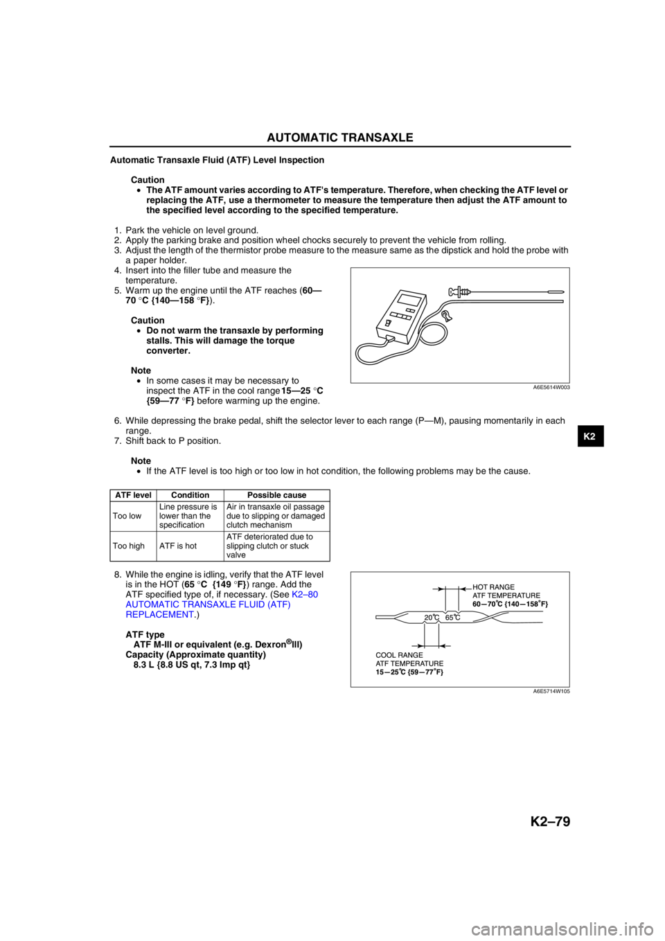
Automatic Transaxle Fluid (ATF) Level Inspection
Caution
•The ATF amount varies according to ATF's temperature. Therefore, when checking the ATF level or
replacing the ATF, use a thermometer to measure the temperature then adjust the ATF amount to
the specified level according to the specified temperature.
1. Park the vehicle on level ground.
2. Apply the parking brake and position wheel chocks securely to prevent the vehicle from rolling.
3. Adjust the length of the thermistor probe measure to the measure same as the dipstick and hold the probe with
a paper holder.
4. Insert into the filler tube and measure the
temperature.
5. Warm up the engine until the ATF reaches (60—
70 °C {140—158 °F}).
Caution
•Do not warm the transaxle by performing
stalls. This will damage the torque
converter.
Note
•In some cases it may be necessary to
inspect the ATF in the cool range 15—25 °C
{59—77 °F} before warming up the engine.
6. While depressing the brake pedal, shift the selector lever to each range (P—M), pausing momentarily in each
range.
7. Shift back to P position.
Note
•If the ATF level is too high or too low in hot condition, the following problems may be the cause.
8. While the engine is idling, verify that the ATF level
is in the HOT (65 °C {149 °F}) range. Add the
ATF specified type of, if necessary. (See K2–80
AUTOMATIC TRANSAXLE FLUID (ATF)
REPLACEMENT.)
ATF type
ATF M-III or equivalent (e.g. Dexron
®III)
Capacity (Approximate quantity)
8.3 L {8.8 US qt, 7.3 Imp qt}
End Of Sie
ATF level Condition Possible cause
Too lowLine pressure is
lower than the
specificationAir in transaxle oil passage
due to slipping or damaged
clutch mechanism
Too high ATF is hotATF deteriorated due to
slipping clutch or stuck
valve
A6E5614W003
A6E5714W105
Page 495 of 909
K2–80
AUTOMATIC TRANSAXLE
AUTOMATIC TRANSAXLE FLUID (ATF) REPLACEMENTA6E571419001202
Warning
•When the transaxle and ATF are hot, they can badly burn you. Turn off the engine and wait until
they are cool before changing the ATF.
1. Remove the oil dipstick.
2. Remove the oil drain plug and washer.
3. Drain the ATF into a container.
4. Install a new washer and the drain plug.
Tightening torque
39—54 N·m {3.9—5.6 kgf·m, 29—40 ft·lbf}
5. Add the specified type of ATF through the oil filler
tube, until ATF level reaches lower notch of
dipstick.
ATF type
ATF M-III or equivalent (e.g. Dexron
®III)
Capacity (Approximate quantity)
8.3 L {8.8 US qt, 7.3 Imp qt}
6. Verify that the ATF level is in the HOT (65 °C {149 °F}) range.
•Add ATF to the specified level as necessary.
End Of Sie
TRANSAXLE RANGE (TR) SWITCH INSPECTIONA6E571419440201
Note
•Input signals of the TR switch can be inspected with a WDS or equivalent. (See K2–90 TCM
INSPECTION.)
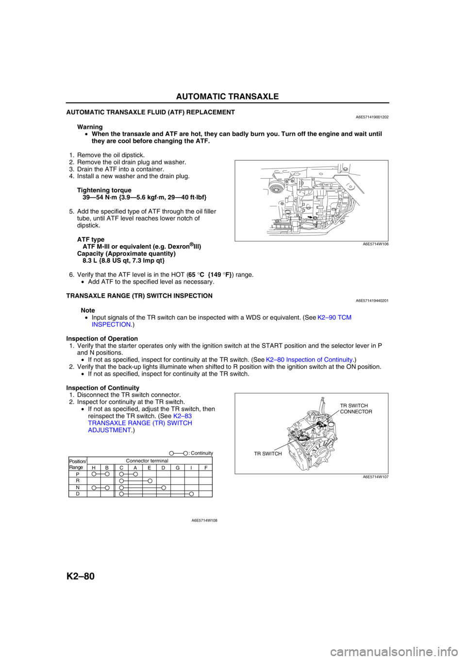
Inspection of Operation
1. Verify that the starter operates only with the ignition switch at the START position and the selector lever in P
and N positions.
•If not as specified, inspect for continuity at the TR switch. (See K2–80 Inspection of Continuity.)
2. Verify that the back-up lights illuminate when shifted to R position with the ignition switch at the ON position.
•If not as specified, inspect for continuity at the TR switch.
Inspection of Continuity
1. Disconnect the TR switch connector.
2. Inspect for continuity at the TR switch.
•If not as specified, adjust the TR switch, then
reinspect the TR switch. (See K2–83
TRANSAXLE RANGE (TR) SWITCH
ADJUSTMENT.)
A6E5714W106
TR SWITCHTR SWITCH
CONNECTOR
A6E5714W107
Position/
Range
H
P
R
N
DBCAEDGI FConnector terminal: Continuity
A6E5714W108
Page 499 of 909
K2–84
AUTOMATIC TRANSAXLE
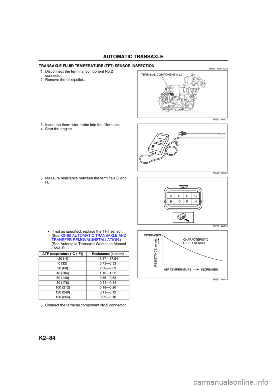
TRANSAXLE FLUID TEMPERATURE (TFT) SENSOR INSPECTIONA6E5714190102021. Disconnect the terminal component No.2
connector.
2. Remove the oil dipstick.
3. Insert the thermistor probe into the filler tube.
4. Start the engine.
5. Measure resistance between the terminals G and
H.
•If not as specified, replace the TFT sensor.
(See K2–99 AUTOMATIC TRANSAXLE AND
TRANSFER REMOVAL/INSTALLATION.)
(See Automatic Transaxle Workshop Manual
JA5A-EL.)
6. Connect the terminal component No.2 connector.
End Of Sie
ATF temperature (°C {°F}) Resistance (kilohm)
-20 {-4} 15.87—17.54
0 {32} 5.73—6.33
20 {68} 2.38—2.63
40 {104} 1.10—1.22
60 {140} 0.56—0.62
80 {176} 0.31—0.34
100 {212} 0.18—0.20
120 {248} 0.11—0.12
130 {266} 0.09—0.10
TERMINAL COMPONENT No.2
A6E5714W117
A6E5614W003
ACEG
BDFH
A6E5714W118
INCREASES
RESISTANCE (ohm)
ATF TEMPERATURE INCREASESCHARACTERISTIC
OF TFT SENSOR
A6E5714W119