wheel torque MAZDA 6 2002 Workshop Manual Suplement
[x] Cancel search | Manufacturer: MAZDA, Model Year: 2002, Model line: 6, Model: MAZDA 6 2002Pages: 909, PDF Size: 17.16 MB
Page 10 of 909

ABBREVIATIONS
GI–7
GIABBREVIATIONS TABLEA6E203000011202
End Of Sie
ABBREVIATIONS
A/C Air conditioner
ABS Antilock brake system
ACC Accessories
ABDC After bottom dead center
ATDC After top dead center
ATF Automatic transaxle fluid
ATX Automatic transaxle
BBDC Before bottom dead center
BDC Bottom dead center
BTDC Before top dead center
CAN Controller area network
CM Control module
DEI Double electronic ignition
DOHC Double overhead camshaft
DSC Dynamic stability control
ESA Electronic spark advance
EX Exhaust
HI High
HU Hydraulic unit
IDM Injector driver module
IG Ignition
IN Intake
KOEO Key on engine off
KOER Key off engine running
LH Left hand
L.H.D. Left hand drive
LO Low
LR Left rear
M Motor
MAX Maximum
MTX Manual transaxle
MIN Minimum
O/D Overdrive
OCV Oil control valveOFF Switch off
ON Switch on
P/S Power steering
PATS Passive anti-theft system
PCV Positive crankcase ventilation
PID Parameter identification
RF Right front
RH Right hand
R.H.D. Right hand drive
RR Right rear
SST Special service tool
SW Switch
TCC Torque converter clutch
TCM Transaxle control module
TDC Top dead center
TFT Transaxle fluid temperature
TNS Tail number side lights
TR Transaxle range
TWC Three way catalytic converter
VAD Variable air duct
VBC Variable boost control
VIS Variable intake-air system
VSC Variable swirl control
VSS Vehicle speedometer sensor
VTCS Variable tumble control system
WGN Wagon
WDS Worldwide diagnostic system
1GR 1st gear
2GR 2nd gear
4GR 4th gear
5GR 5th gear
4SD 4 door sedan
5HB 5 door hatchback
4WD 4 wheel drive
Page 109 of 909

CONTROL SYSTEM
F1–21
F1
CONTROLLER AREA NETWORK (CAN)A6E394018880205•PCM transmit/received the information in the CAN. For detail information of the CAN, see the “MULTIPLEX
COMMUNICATION SYSTEM.” (See T–3 OUTLINE.)
Transmit Information (4WD ATX Model)
•Engine control condition
•Torque reduction inhibit
•Engine speed
•Vehicle Speed
•TP
•Engine torque (without torque reduction)
•Engine torque (with torque reduction)
•Battery reconnection
•Engine loss torque
•ECT
•Travelled distance
•Fuel injection information
•MIL condition
•Generator warning light conditions
•Engine displacement
•Number of cylinders
•Air induction type
•Fuel type and delivery
•Country
•Transmission/axle type
•Tire circumference (front/rear)
Received Information (4WD ATX Model)
From ABS HU/CM, ABS/TCS HU/CM, or DSC HU/CM
•Wheel speed
—Front left, Front right, Rear left, and Rear right
•Travelled distance
•Brake system status
•Torque reduction request
•Brake system configuration
From TCM
•Desired torque
•Upper torque limit
•Turbineshaft speed
•Vehicle speed
•Torque reduction request
•Idle speed up request
•Racing select determination
•MIL indicate request
•Desired gear/selector lever position
•AT warning indicator light condition
•TCC condition
End Of Sie
Page 176 of 909

F2–24
CONTROL SYSTEM, ON-BOARD DIAGNOSTIC
CONTROLLER AREA NETWORK (CAN)A6E404018881206Outline
•The PCM transmit/received the information other units using CAN to simplify the system.
Transmit Information
•Engine speed
•Vehicle speed
•Accelerator pedal position
•Fuel injection information
•Torque reduction inhibit
•Intake air temperature
•Engine coolant temperature
•Travelled distance
•Glow indicator light conditions
•Engine displacement
•Number of cylinders
•Air induction type
•Fuel type and delivery
•Country
•Transmission/axle type
•Tire circumference (front/rear)
•Cruise main indicator light conditions
•Cruise set indicator light conditions
Received Information
•Torque reduction request from DSC HU/CM
•Wheel speed from ABS HU/CM or DSC HU/CM
—Front left
—Front right
•Travelled distance from ABS HU/CM or DSC HU/CM
End Of Sie
OUTLINEA6E407018881201•The on-board diagnostic system is essentially carried over from that of the current MPV (LW) MZR-CD (RF
Turbo) engine models, except for the following. (See MPV Workshop Manual Supplement 1737-1*-02C.)
—DTCs, PID monitoring items, and simulation items have been changed.
—KOEO/KOER self-test items have been changed.
End Of Sie
DTCA6E407018881202
×: Applicable –: Not applicable
ON-BOARD DIAGNOSTIC
DTC Condition Detection condition MILMemory
function
P0016Crankshaft position-camshaft position
correlation malfunctionInput signals from CKP sensor and CMP sensor
are misaligned.××
P0088 Fuel pressure system too highFuel pressure is higher than preprogrammed
criteria.–×
P0091 Suction control valve circuit low inputInput voltage from suction control valve does not
change from off to on.××
P0092 Suction control valve circuit high inputInput voltage from suction control valve does not
change from on to off.××
P0093 Fuel system leak detectionFuel pressure after fuel injection is lower than
preprogrammed criteria.××
P0097 IAT sensor No.1 circuit low input Input voltage from IAT sensor No.1 is below 0.1 V.××
P0098 IAT sensor No.1 circuit high input Input voltage from IAT sensor No.1 is above 5.0 V.××
P0102 MAF sensor circuit low input Input voltage from MAF sensor is below 0.2 V.××
P0103 MAF sensor circuit high input Input voltage from MAF sensor is above 4.9 V.××
P0107 Boost sensor circuit low inputInput voltage from boost sensor is below 1.9 V
when engine speed is 2,400 rpm or above and
accelerator opening angle is 50% or above.××
P0108 Boost sensor circuit high input Input voltage from boost sensor is above 4.9 V.××
Page 396 of 909

H–2
OUTLINE
OUTLINE OF CONSTRUCTIONA6E490216003201•The construction and operation of the clutch is essentially carried over from that of the current MPV (LW)
models, except for the following features. (See Mazda MPV Training Manual 3340-1*-99F.)
End Of Sie
FEATURESA6E490216003202Adoption of the A65M-R manual transaxle models
•The specifications for the A65M-R manual transaxle models have been added.
Increased torque transmission capacity
•Increased clutch cover set load.
Reduced noise
•The flywheel with a damper has been adopted for the A65M-R manual transaxle model.
End Of Sie
SPECIFICATIONSA6E490216003203
Bold frames:New specifications
End Of Sie
SUPPLEMENTAL SERVICE INFORMATIONA6E490216003204•The following changes have been made since publication of the Mazda6 Workshop Manual (1730-1*-02C).
CLUTCH RELEASE CYLINDER
•Removal/installation procedure has been modified.
•Disassembly/assembly procedure has been modified.
CLUTCH UNIT
•Removal/installation procedure has been modified.
•Clutch cover inspection procedure has been modified.
FLYWHEEL
•Flywheel inspection procedure has been modified.
End Of Sie
OUTLINE
Item New Mazda6 (GG, GY) Current MPV (LW)
EngineMZR-CD (RF Turbo)
Manual transaxle type A65M-R
Clutch control Hydraulic
Clutch coverSpring type Diaphragm
Set load (N {kgf, lbf}) 6,550 {668, 1,472}
Clutch discOuter diameter (mm {in}) 239 {9.41}
Inner diameter (mm {in}) 160 {6.30}
Clutch pedalType Suspended
Pedal ratio 5.9 6.41
Full stroke (mm {in}) 140 {5.51} 148 {5.83}
Clutch master cylinder inner diameter (mm {in}) 15.87 {0.625}
Clutch release cylinder inner diameter (mm {in}) 19.05 {0.750}
Clutch fluid type SAE J1703, FMVSS116 DOT-3 or DOT-4
OUTLINE
Page 400 of 909

H–6
CLUTCH UNIT
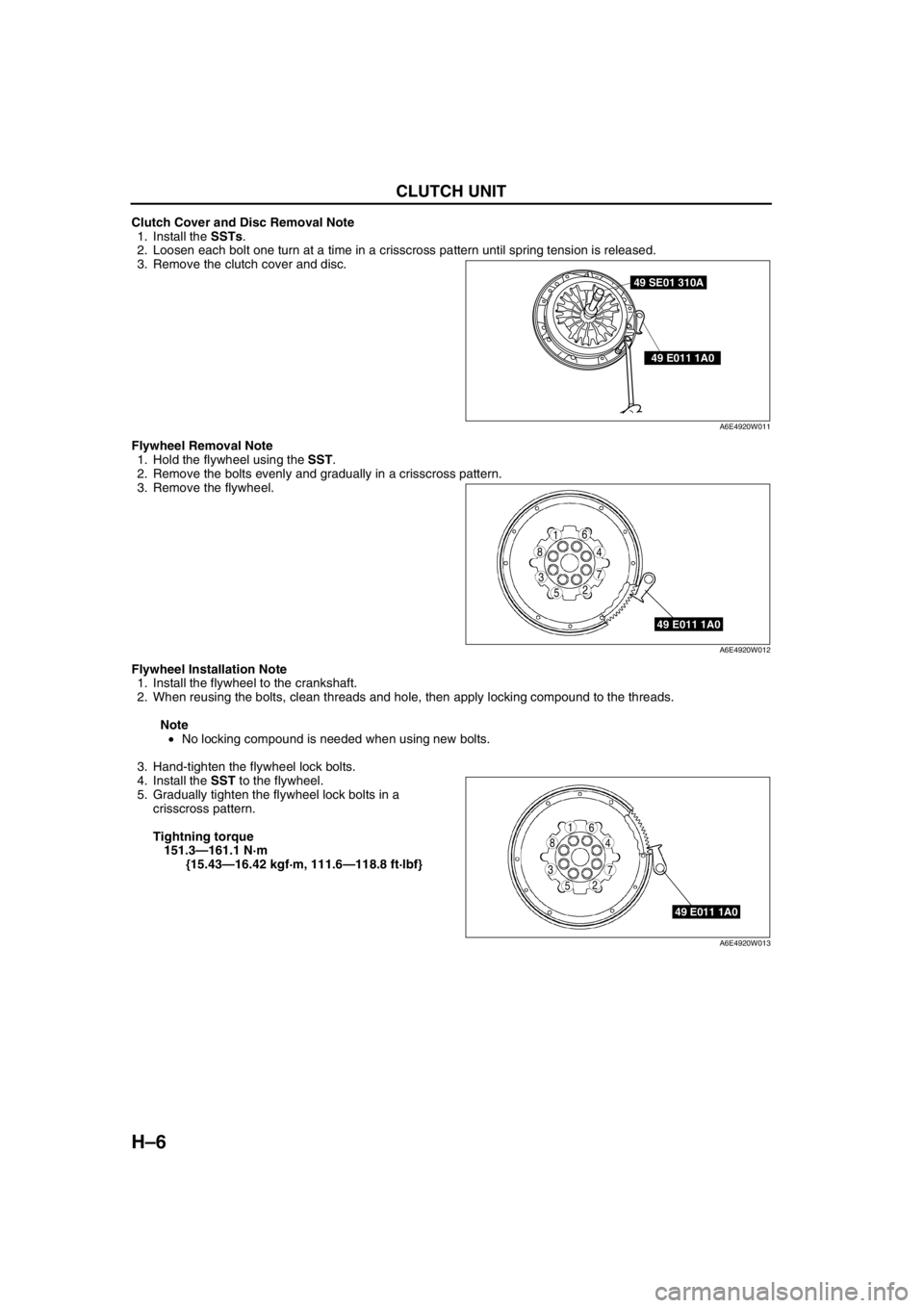
Clutch Cover and Disc Removal Note
1. Install the SSTs.
2. Loosen each bolt one turn at a time in a crisscross pattern until spring tension is released.
3. Remove the clutch cover and disc.
Flywheel Removal Note
1. Hold the flywheel using the SST.
2. Remove the bolts evenly and gradually in a crisscross pattern.
3. Remove the flywheel.
Flywheel Installation Note
1. Install the flywheel to the crankshaft.
2. When reusing the bolts, clean threads and hole, then apply locking compound to the threads.
Note
•No locking compound is needed when using new bolts.
3. Hand-tighten the flywheel lock bolts.
4. Install the SST to the flywheel.
5. Gradually tighten the flywheel lock bolts in a
crisscross pattern.
Tightning torque
151.3—161.1 N·m
{15.43—16.42 kgf·m, 111.6—118.8 ft·lbf}
49 SE01 310A
49 E011 1A0
A6E4920W011
49 E011 1A0
5
4
3
61
2
8
7
A6E4920W012
49 E011 1A0
5
4
3
61
2
8
7
A6E4920W013
Page 409 of 909

MANUAL TRANSAXLE
J2–7
J2
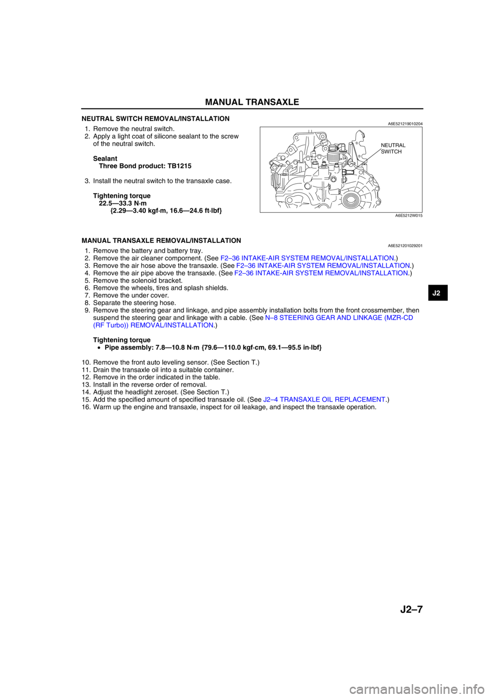
NEUTRAL SWITCH REMOVAL/INSTALLATIONA6E5212190102041. Remove the neutral switch.
2. Apply a light coat of silicone sealant to the screw
of the neutral switch.
Sealant
Three Bond product: TB1215
3. Install the neutral switch to the transaxle case.
Tightening torque
22.5—33.3 N·m
{2.29—3.40 kgf·m, 16.6—24.6 ft·lbf}
End Of Sie
MANUAL TRANSAXLE REMOVAL/INSTALLATIONA6E5212010292011. Remove the battery and battery tray.
2. Remove the air cleaner compornent. (See F2–36 INTAKE-AIR SYSTEM REMOVAL/INSTALLATION.)
3. Remove the air hose above the transaxle. (See F2–36 INTAKE-AIR SYSTEM REMOVAL/INSTALLATION.)
4. Remove the air pipe above the transaxle. (See F2–36 INTAKE-AIR SYSTEM REMOVAL/INSTALLATION.)
5. Remove the solenoid bracket.
6. Remove the wheels, tires and splash shields.
7. Remove the under cover.
8. Separate the steering hose.
9. Remove the steering gear and linkage, and pipe assembly installation bolts from the front crossmember, then
suspend the steering gear and linkage with a cable. (See N–8 STEERING GEAR AND LINKAGE (MZR-CD
(RF Turbo)) REMOVAL/INSTALLATION.)
Tightening torque
•Pipe assembly: 7.8—10.8 N·m {79.6—110.0 kgf·cm, 69.1—95.5 in·lbf}
10. Remove the front auto leveling sensor. (See Section T.)
11. Drain the transaxle oil into a suitable container.
12. Remove in the order indicated in the table.
13. Install in the reverse order of removal.
14. Adjust the headlight zeroset. (See Section T.)
15. Add the specified amount of specified transaxle oil. (See J2–4 TRANSAXLE OIL REPLACEMENT.)
16. Warm up the engine and transaxle, inspect for oil leakage, and inspect the transaxle operation.
NEUTRAL
SWITCH
A6E5212W015
Page 427 of 909

K2–12
AUTOMATIC TRANSAXLE
Electronic Control Item and Control
Component Description (Electronic Control)
Control item Contents
Shift control•Detects engine load condition and vehicle speed. Shifts to the best gear
position according to the programmed automatic shift diagram.
Line pressure control•Generates line pressure matching the engine load condition and driving
conditions. Optimizes line pressure for each shift. When the ATF
temperature is low, automatically optimizes line pressure for quick clutch
engagement.
Revers inhibition control•When the shift lever is shifted to R position while the vehicle is running
forward at approx. 30 km/h{19 mph} or more, the TCM turns the neutral
shift solenoid valve on and drains the low and reverse brake hydraulic
pressure. Due to this, the transaxle shifts to neutral.
Shift transient control•Adjusts transient hydraulic pressure according to engine load and
vehicle driving conditions when shifting using the pressure control
solenoid, 2-4 brake solenoid valve, the high clutch solenoid valve, and
each accumulator control valve.
•Temporarily lowers engine torque during shift (up and down) to improve
shift feel
•The lock timing for the reduction brake band is controlled by the control
of the reduction timing solenoid valve ON/OFF timing.
•The lock timing for the clutch brake is controlled by the control of shift
solenoid A, B, and C ON/OFF timing.
Feedback control•Corrects clutch engagement pressure and timing on drain side to
compensate for changes in engine performance and changes in
transaxle
TCC control•Controls TCC according to the programmed TCC points
N-D select control•When a driving range is selected from P/N, the fuel injection amount is
controlled to prevent fluctuation in engine speed.
Slope mode control•Changes the shift point to prevent frequent shifting up/down when
climbing hills
OBD system•Detects and/or memorizes failure of input/output part and transaxle
condition
Part name Function
Input system TR switch•Detects selector lever ranges/positions
Input/turbine speed sensor•Detects reverse clutch drum revolution speed
Intermediate sensor•Detects output gear revolution speed
Vehicle speedometer sensor•Detects parking gear revolution speed
TFT sensor•Detects the ATF temperature
Brake switch•Detects the brake pedal depressed
Cruise control module (in cruise actuator)•When the cruise control is in use, the signal detects when the
difference between the target speed and actual speed
exceeds specification
M range switch•Detects selector lever shifted M range
Up switch•Detects up shift in M range
Down switch•Detects down shift in M range
CAN signal Throttle position signal•Input throttle opening angle from PCM
Engine torque signal
(without torque down)•Input engine torque from PCM
Engine torque signal (with
torque down)•Input engine torque from PCM
Engine torque signal (loss
torque)•Input engine loss torque from PCM
Torque reduced signal•Detects signals indicating torque down availability
Engine coolant
temperature signal•Input engine coolant temperature from PCM
Engine speed signal•Input engine speed from PCM
Battery OFF signal•Detect negative battery cable disconnected
4 wheel speed signal•Input wheel speed from ABS HU/CM or DSC HU/CM
Page 494 of 909

AUTOMATIC TRANSAXLE
K2–79
K2
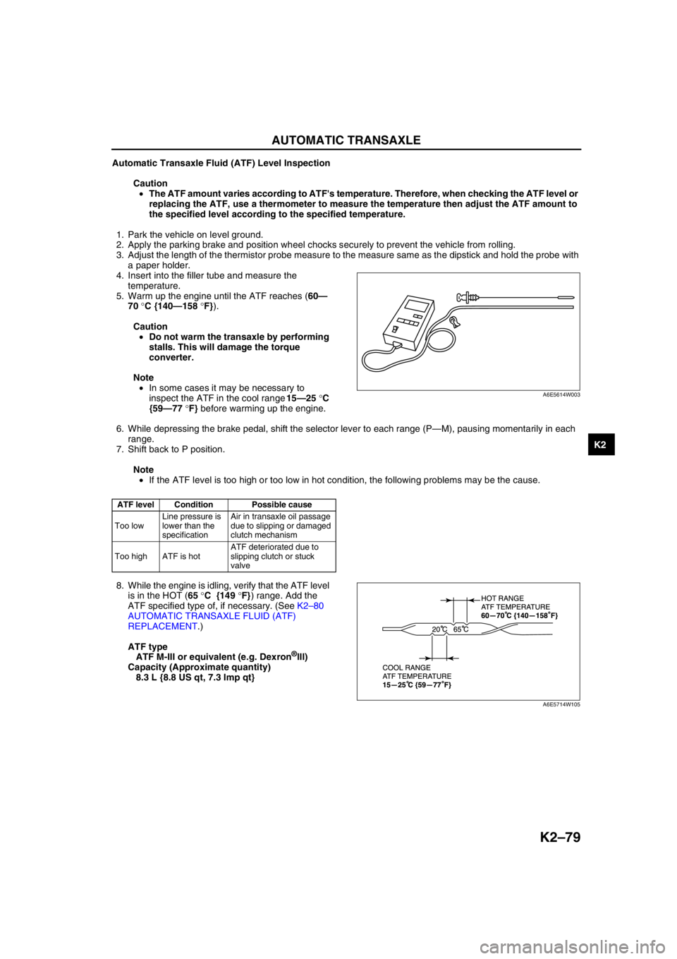
Automatic Transaxle Fluid (ATF) Level Inspection
Caution
•The ATF amount varies according to ATF's temperature. Therefore, when checking the ATF level or
replacing the ATF, use a thermometer to measure the temperature then adjust the ATF amount to
the specified level according to the specified temperature.
1. Park the vehicle on level ground.
2. Apply the parking brake and position wheel chocks securely to prevent the vehicle from rolling.
3. Adjust the length of the thermistor probe measure to the measure same as the dipstick and hold the probe with
a paper holder.
4. Insert into the filler tube and measure the
temperature.
5. Warm up the engine until the ATF reaches (60—
70 °C {140—158 °F}).
Caution
•Do not warm the transaxle by performing
stalls. This will damage the torque
converter.
Note
•In some cases it may be necessary to
inspect the ATF in the cool range 15—25 °C
{59—77 °F} before warming up the engine.
6. While depressing the brake pedal, shift the selector lever to each range (P—M), pausing momentarily in each
range.
7. Shift back to P position.
Note
•If the ATF level is too high or too low in hot condition, the following problems may be the cause.
8. While the engine is idling, verify that the ATF level
is in the HOT (65 °C {149 °F}) range. Add the
ATF specified type of, if necessary. (See K2–80
AUTOMATIC TRANSAXLE FLUID (ATF)
REPLACEMENT.)
ATF type
ATF M-III or equivalent (e.g. Dexron
®III)
Capacity (Approximate quantity)
8.3 L {8.8 US qt, 7.3 Imp qt}
End Of Sie
ATF level Condition Possible cause
Too lowLine pressure is
lower than the
specificationAir in transaxle oil passage
due to slipping or damaged
clutch mechanism
Too high ATF is hotATF deteriorated due to
slipping clutch or stuck
valve
A6E5614W003
A6E5714W105
Page 633 of 909

OUTLINE
M–3
M
4WD
Bold frames:New specifications
End Of Sie
ItemSpecification
New Mazda6 (GY)(Wagon 4WD)
EngineL3
TransaxleATX
Front axle Bearing type Angular ball bearing
Rear axle Bearing type Angular ball bearing
Front drive shaftJoint typeWheel side Bell joint
Differential side Tripod joint (With free ring)
Shaft diameter (mm {in}) 24.0 {0.94}
Joint shaft Shaft diameter (mm {in}) 29.0 {1.14}
Rear drive shaftJoint typeWheel side Bell joint
Differential side Double offset joint
Shaft diameter (mm {in}) 22.0 {0.87}
Rear and front wheel torque distribution unit Electronic control coupling
Rear differentialReduction gear Hypoid gear
Differential gear Straight bevel gear
Ring gear size (Inches) 6.5
Final gear ratio 2.928
Gears:
Number of teethDrive pinion 14
Ring gear 41
Differential oilTypeGrade API service GL-5
ViscosityAbove –18°C {0°F}: SAE 90
Below –18°C {0°F}: SAE 80
Amount
(Approximate quantity)(L {US qt, lmp qt}) 1.0 {1.1, 0.9}
Page 637 of 909

ELECTRONIC 4WD CONTROL SYSTEM
M–7
M
OUTLINEA6E632227100201Features
Improved off-road mobility, handling stability, operability, fuel economy and marketability
•An electronic 4WD control system, which automatically optimizes traction distribution to the front and rear
wheels, has been adopted.
Improved serviceability
•A self-diagnostic function has been adopted for the electronic 4WD control system.
Electronic 4WD control system outline
•The newly adopted electronic 4WD control system automatically and optimally controls drive torque distribution
for the front and rear wheels. Due to this off-road mobility, driving stability and fuel economy are improved.
•Based on the input signals from each sensor, the 4WD control modure (4WD CM) determines vehicle driving
and road conditions, and controls output current to the electronic control coupling (4WD solenoid) inside the
rear differential. This control allows for optimal distribution of the drive torque from the engine to the rear
wheels.
•Also, the 4WD CM automatically controls the 4WD, greatly reducing the load on the driver and improving
operability.
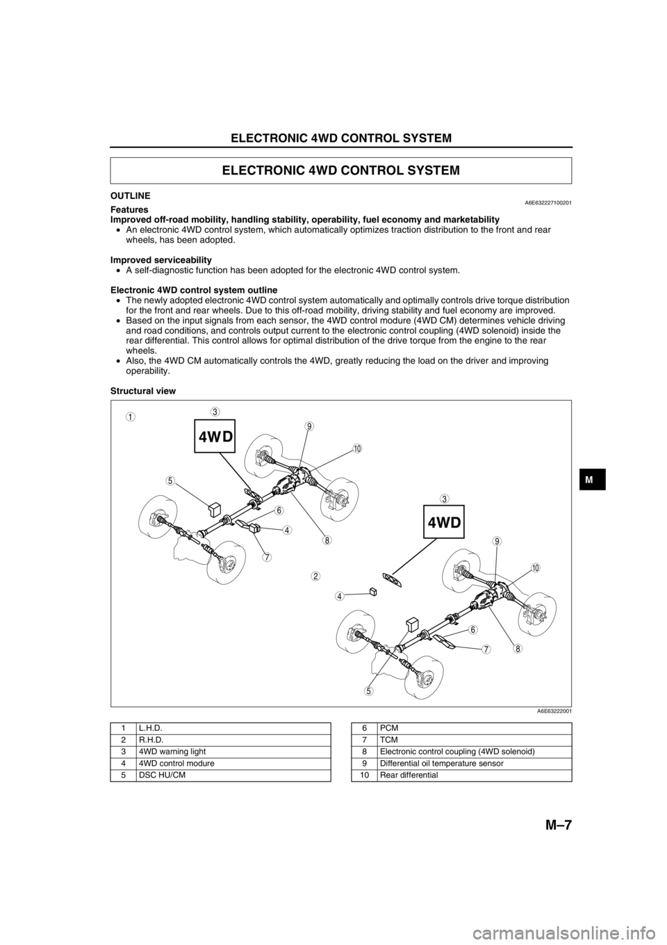
Structural view
.
ELECTRONIC 4WD CONTROL SYSTEM
87
5
4
3
6
9
8
7
5
4
3
10
6
1
2
9
10
A6E63222001
1L.H.D.
2 R.H.D.
3 4WD warning light
4 4WD control modure
5 DSC HU/CM6PCM
7TCM
8 Electronic control coupling (4WD solenoid)
9 Differential oil temperature sensor
10 Rear differential