radiator cap MAZDA 6 2002 Workshop Manual Suplement
[x] Cancel search | Manufacturer: MAZDA, Model Year: 2002, Model line: 6, Model: MAZDA 6 2002Pages: 909, PDF Size: 17.16 MB
Page 76 of 909

E–1
E
ECOOLING SYSTEM
OUTLINE................................................................ E-2
OUTLINE OF CONSTRUCTION.......................... E-2
FEATURES .......................................................... E-2
SPECIFICATIONS ............................................... E-3
COOLING SYSTEM................................................ E-4
STRUCTURAL VIEW ........................................... E-4
COOLING FLOW DIAGRAM ............................... E-5
COOLING FAN .................................................... E-5
OUTLINE................................................................ E-6
SUPPLEMENTAL SERVICE INFORMATION ..... E-6
LOCATION INDEX ............................................... E-6
RADIATOR CAP..................................................... E-7
RADIATOR CAP INSPECTION ........................... E-7
ENGINE COOLANT................................................ E-8
ENGINE COOLANT LEAKAGE INSPECTION .... E-8
THERMOSTAT....................................................... E-9
THERMOSTAT REMOVAL/INSTALLATION ....... E-9
THERMOSTAT INSPECTION ........................... E-10
WATER PUMP...................................................... E-11
WATER PUMP REMOVAL/INSTALLATION...... E-11
FAN MOTOR........................................................ E-12
COOLING FAN MOTOR
REMOVAL/INSTALLATION ............................ E-12
COOLING FAN MOTOR INSPECTION ............. E-13 FEATURES
SERVICE
Page 78 of 909

OUTLINE
E–3
E
SPECIFICATIONSA6E360202000209Gasoline engine
Bold frames: New specifications
Diesel engine
Bold frames: New specifications
End Of Sie
ItemSpecification
New
Mazda6
(GG, GY)Current
Mazda6
(GG)New
Mazda6
(GG, GY)Current
Mazda6
(GG)New
Mazda6
(GG, GY)Current
Mazda6
(GG)
L8 LF L3
Cooling system Water-cooled
Coolant capacity
(approximate quantity)(L {US qt, lmp qt}) 7.5 {7.9, 6.6}
Water pump TypeCentrifugal,
V-ribbed belt-driven
ThermostatTypeWax,
Bottom-bypass
Opening temperature (°C {°F}) 80—84 {176—183}
Full-open temperature (°C {°F}) 97 {206}
Full-open lift (mm {in}) More than 8.0 {0.31}
RadiatorType Corrugated fin
Cap valve opening pressure
113—142
{1.15—1.44, 16.4—20.4}
(kPa {kgf/cm
2, psi})
Cooling fanType Electric
BladeOuter
diameter(mm {in}) 300 {11.8} 320 {12.6}
Number of
blade(sheet)Cooling fan No.1: 5
Cooling fan No.2: 7Cooling fan No.1: 7
Cooling fan No.2: 5
ItemSpecification
New Mazda6
(GG, GY)Current Mazda 323
(BJ)
MZR-CD (RF Turbo) RF Turbo
Cooling system Water-cooled
Coolant capacity
(approximate quantity)(L {US qt, lmp qt}) 9.0 {9.5, 7.9}
Water pump TypeCentrifugal,
Timing-belt driven
ThermostatType Wax, Bottom-bypass
Opening temperature (°C {°F}) 80—84 {176—183}
Full-open temperature (°C {°F}) 95 {203}
Full-open lift (mm {in}) More than 8.5 {0.33}
RadiatorType Corrugated fin
Cap valve opening pressure
94—122
{0.96—1.24, 13.7—17.6}
(kPa {kgf/cm
2, psi})
Cooling fanType Electric
BladeOuter
diameter(mm {in}) 320 {12.6} 300 {11.9}
Number of
blade(sheet)Cooling fan No.1: 7
Cooling fan No.2: 54
Page 81 of 909

E–6
OUTLINE
SUPPLEMENTAL SERVICE INFORMATIONA6E360202000208•The following changes and/or additions have been made since publication of the Mazda6 Workshop Manual
(1730-1*-02C).
Radiator cap
•Inspection procedure has been added. (MZR-CD (RF Turbo) engine model)
Thermostat
•Removal/Installation procedure has been added. (MZR-CD (RF Turbo) engine model)
•Inspection procedure has been added. (MZR-CD (RF Turbo) engine model)
Water pump
•Removal/Installation procedure has been added. (MZR-CD (RF Turbo) engine model)
Fan motor
•Removal/Installation procedure has been added. (MZR-CD (RF Turbo) engine model)
•Inspection procedure has been added. (MZR-CD (RF Turbo) engine model)
End Of Sie
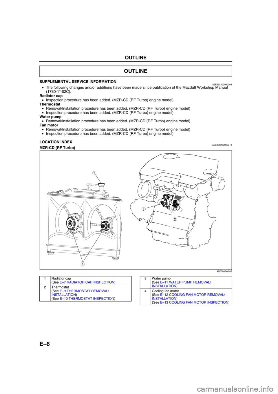
LOCATION INDEXA6E360202000210MZR-CD (RF Turbo)
.
End Of Sie
OUTLINE
4
3
1
2
A6E3602W202
1 Radiator cap
(See E–7 RADIATOR CAP INSPECTION)
2Thermostat
(See E–9 THERMOSTAT REMOVAL/
INSTALLATION)
(See E–10 THERMOSTAT INSPECTION)3 Water pump
(See E–11 WATER PUMP REMOVAL/
INSTALLATION)
4 Cooling fan motor
(See E–12 COOLING FAN MOTOR REMOVAL/
INSTALLATION)
(See E–13 COOLING FAN MOTOR INSPECTION)
Page 82 of 909

RADIATOR CAP
E–7
E
RADIATOR CAP INSPECTIONA6E361415201201MZR-CD (RF Turbo)
Warning
•Never remove the radiator cap while the engine is running, or when the engine and radiator are
hot. Scalding coolant and steam may shoot out and cause serious injury. It may also damage the
engine and cooling system.
•Turn off the engine and wait until it is cool. Even then, be very careful when removing the cap.
Wrap a thick cloth around it and slowly turn it counterclockwise to the first stop. Step back while
the pressure escapes.
•When you are sure all the pressure is gone, press down on the cap using the cloth, turn it, and
remove it.
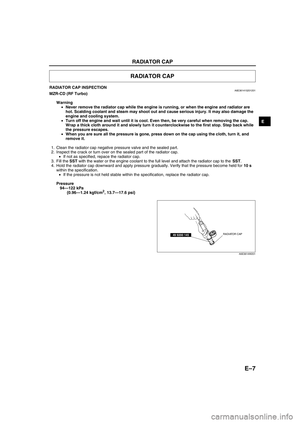
1. Clean the radiator cap negative pressure valve and the sealed part.
2. Inspect the crack or turn over on the sealed part of the radiator cap.
•If not as specified, repace the radiator cap.
3. Fill the SST with the water or the engine coolant to the full level and attach the radiator cap to the SST.
4. Hold the radiator cap downward and apply pressure gradually. Verify that the pressure become held for 10 s
within the specification.
•If the pressure is not held stable within the specification, replace the radiator cap.
Pressure
94—122 kPa
{0.96—1.24 kgf/cm
2, 13.7—17.6 psi}
End Of Sie
RADIATOR CAP
RADIATOR CAP49 9200 145
A6E3614W201
Page 83 of 909

E–8
ENGINE COOLANT
ENGINE COOLANT LEAKAGE INSPECTIONA6E361215201201MZR-CD (RF Turbo)
Warning
•Never remove the radiator cap while the engine is running, or when the engine and radiator are
hot. Scalding coolant and steam may shoot out and cause serious injury. It may also damage the
engine and cooling system.
•Turn off the engine and wait until it is cool. Even then, be very careful when removing the cap.
Wrap a thick cloth around it and slowly turn it counterclockwise to the first stop. Step back while
the pressure escapes.
•When you are sure all the pressure is gone, press down on the cap using the cloth, turn it, and
remove it.
1. Inspect the coolant level.
2. Remove the radiator cap.
3. Clean the mounting surface of the rediator cap and the upper radiator hose.
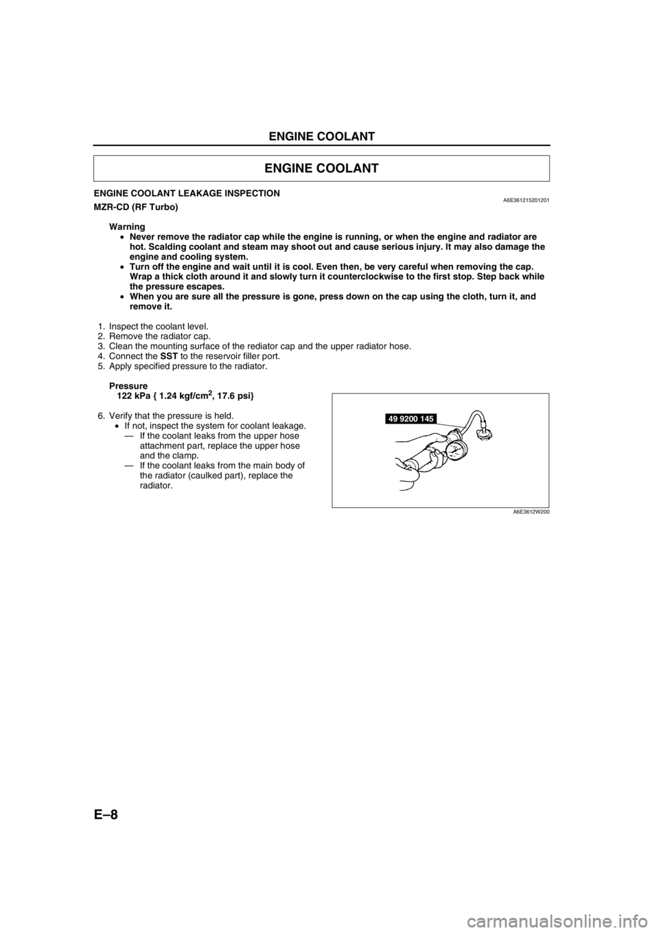
4. Connect the SST to the reservoir filler port.
5. Apply specified pressure to the radiator.
Pressure
122 kPa { 1.24 kgf/cm
2, 17.6 psi}
6. Verify that the pressure is held.
•If not, inspect the system for coolant leakage.
—If the coolant leaks from the upper hose
attachment part, replace the upper hose
and the clamp.
—If the coolant leaks from the main body of
the radiator (caulked part), replace the
radiator.
End Of Sie
ENGINE COOLANT
49 9200 145
A6E3612W200
Page 362 of 909

F2–210
TROUBLESHOOTING
End Of SieNO.17 COOLING SYSTEM CONCERNS-OVERHEATINGA6E408018881219
Diagnostic Procedure
17
COOLING SYSTEM CONCERNS-OVERHEATING
DESCRIPTION•Engine runs at higher than normal temperature/overheats.
POSSIBLE
CAUSE•Cooling fan No.2 malfunction
•Cooling fan No.1 malfunction
•Low drive belt tension
•Drive belt damage
•Improper coolant level
•Thermostat malfunction
•Radiator clogging
•Improper water/anti-freeze mixture
•Improper or damaged radiator cap
•Radiator hose damage
•Coolant leakage (engine internal, turbocharger, external)
•A/C system malfunction
•EGR system malfunction
•Coolant heater system malfunction
STEP INSPECTION RESULTS ACTION
1 Inspect following:
•Engine coolant level
•Coolant leakage (around heater unit in
passenger compartment, coolant hoses and/
or radiator, and around coolant heater unit.)
•Water and anti-freeze mixture
•Radiator condition
•Collapsed or restricted radiator hoses
•Radiator pressure cap
•Drive belt tension
•Drive belt
•Fan rotational direction
Are all items okay?Yes Go to next step.
No Service as necessary.
Repeat Step 1.
2 Perform self-test function using WDS or
equivalent.
Turn engine switch to ON.
Retrieve any DTC.
Is DTC displayed?YesDTC is displayed:
Go to appropriate DTC test.
Communication error message is displayed:
Inspect for following:
•Open circuit between PCM control relay and PCM
terminal 53 or 79
•Open circuit PCM control relay and PCM terminal
69
•PCM control relay stuck open
•Open or poor GND circuit (PCM terminal 65, 85,
103 or 104)
•Poor connection vehicle body GND
NoNo DTC is displayed:
Go to next step.
Page 895 of 909

TECHNICAL DATA
TD–3
TD
Recommended engine oil
Note
•The maintenance intervals on scheduled maintenance table (See GI–8 SCHEDULED MAINTENANCE
TABLE) can only be supported with the use of following oils.
End Of Sie
COOLING SYSTEMA6E931001001203
End Of Sie
FUEL AND EMISSION CONTROL SYSTEMA6E931001001204
*1: Excludes temporary idle speed drop just after the electrical loads are turned on.
End Of Sie
ItemSpecification
Diesel engine
MZR-CD (RF Turbo)
Engine oil GradeAPI CF CD, CE, CF-4
ACEA B1 or B3
B3B3 or B4
Viscosity (SAE) 5W-30 10W-40 5W-30, 10W-30
RemarksMazda genuine Dexelia oil e.g. —
ItemSpecification
Diesel engine
MZR-CD (RF Turbo)
Coolant capacity (L {US qt, Imp qt}) 9.0 {9.5, 7.9}
Radiator capCap valve opening pressure
94—122
{0.96—1.24, 13.7—17.6}
(kPa {kgf/cm
2, psi})
ThermostatType Wax, bottom-bypass
Initial-opening temperature (°C {°F})80—84
{176—183}
Full-opening temperature (°C {°F}) 95 {203}
Full-open lift (mm {in}) More than 8.5 {0.33}
Cooling fan Motor Current (A)4.4—7.4 (Cooling fan motor No.1)
6.3—9.3 (Cooling fan motor No.2)
ItemEngine
L3 (4WD)
Idle speed
*1(rpm) 650—750 (700±50)
ItemEngine
MZR-CD (RF Turbo)
Idle speed (rpm) 725—825 (775±50)
Idle-up speed (rpm) When A/C is operated 725—825 (775±50)
Boost relief pressure (kPa {mmHg, inHg}) Approx. –14.5 {–108, –4.27}
Page 903 of 909

ST–2
SPECIAL TOOLS
ENGINEA6E941001001205
End Of Sie
LUBRICATION SYSTEMA6E941001001206
End Of Sie
COOLING SYSTEMA6E941001001207
End Of Sie
SPECIAL TOOLS
49 S120 710
Coupling flange
holder 49 G033 107A
Dust cover
installer49 S120 215B
Pulley puller
49 G011 106
Camshaft pulley
puller49 S013 1A1
Compression
gauge set49 B010 002
Oil seal installer
49 G012 0A0
Tappet adjust
wrench set49 G011 105
Crankshaft lock
tool49 U027 003
Oil seal installer
WDS 49 E017 5A0
Engine support
set
—
49 0187 280A
Oil pressure
gauge
——
49 9200 145
Radiator cap
tester adapter
set——