steering wheel MAZDA 6 2002 Workshop Manual Suplement
[x] Cancel search | Manufacturer: MAZDA, Model Year: 2002, Model line: 6, Model: MAZDA 6 2002Pages: 909, PDF Size: 17.16 MB
Page 10 of 909

ABBREVIATIONS
GI–7
GIABBREVIATIONS TABLEA6E203000011202
End Of Sie
ABBREVIATIONS
A/C Air conditioner
ABS Antilock brake system
ACC Accessories
ABDC After bottom dead center
ATDC After top dead center
ATF Automatic transaxle fluid
ATX Automatic transaxle
BBDC Before bottom dead center
BDC Bottom dead center
BTDC Before top dead center
CAN Controller area network
CM Control module
DEI Double electronic ignition
DOHC Double overhead camshaft
DSC Dynamic stability control
ESA Electronic spark advance
EX Exhaust
HI High
HU Hydraulic unit
IDM Injector driver module
IG Ignition
IN Intake
KOEO Key on engine off
KOER Key off engine running
LH Left hand
L.H.D. Left hand drive
LO Low
LR Left rear
M Motor
MAX Maximum
MTX Manual transaxle
MIN Minimum
O/D Overdrive
OCV Oil control valveOFF Switch off
ON Switch on
P/S Power steering
PATS Passive anti-theft system
PCV Positive crankcase ventilation
PID Parameter identification
RF Right front
RH Right hand
R.H.D. Right hand drive
RR Right rear
SST Special service tool
SW Switch
TCC Torque converter clutch
TCM Transaxle control module
TDC Top dead center
TFT Transaxle fluid temperature
TNS Tail number side lights
TR Transaxle range
TWC Three way catalytic converter
VAD Variable air duct
VBC Variable boost control
VIS Variable intake-air system
VSC Variable swirl control
VSS Vehicle speedometer sensor
VTCS Variable tumble control system
WGN Wagon
WDS Worldwide diagnostic system
1GR 1st gear
2GR 2nd gear
4GR 4th gear
5GR 5th gear
4SD 4 door sedan
5HB 5 door hatchback
4WD 4 wheel drive
Page 21 of 909

SCHEDULED MAINTENANCE
GI–17
GI
Scheduled Maintenance Service (Specific Work Required)
•The specific work required for each maintenance item is listed in the following table. (Please refer to the section
applicable to the model serviced.)
For Europe (L.H.D. U.K.)
Bold frames: New item
Maintenance Item Specific Work Required
ENGINE
Engine valve clearance Measure clearance
Drive beltsInspect for wear, cracks and fraying, and check tension.
Replace drive belt.
Engine timing belt Replace engine timing belt.
Engine oil Replace engine oil and inspect for leakage.
Oil filter Replace oil filter and inspect for leakage.
COOLING SYSTEM
Cooling system
(including coolant level adjustment)Check coolant level and quality, and inspect for leakage.
Engine coolant Replace coolant.
FUEL SYSTEM
Air cleaner elementInspect for dirt, oil and damage.
Clean air cleaner element (by blowing air).
Replace air cleaner element.
Fuel filter Replace fuel filter.
Fuel lines and hoses Inspect for cracks, leakage and loose connection.
Fuel injection system (for MZR-CD (RF Turbo)) Update to injection amount correction with WDS. (see W/M)
IGNITION SYSTEM (FOR GASOLINE)
Spark plugsInspect for wear, damage, carbon, high-tension lead condition and measure
plug gap.
Replace spark plugs.
EMISSION CONTROL SYSTEM
Evaporative system (for gasoline)Check system operation (see W/M), vapor lines, vacuum fitting hoses and
connection.
E.G.R. system (MZR-CR (RF Turbo))Check system operation (see W/M), vacuum fitting hoses and connection.
Update to MAF correction for E.G.R control with WDS. (see W/M)
ELECTRICAL SYSTEM
Battery electrolyte level and specific gravity Check level and specific gravity.
CHASSIS AND BODY
Brake fluidCheck fluid level and inspect for leakage.
Replace brake fluid.
Brake lines, hoses and connectionsInspect for cracks, damage, chafing, corrosion, scars, swelling and fluid
leakage.
Parking brake Check lever stroke.
Power brake unit and hosesCheck vacuum lines, connections and check valve for improper attachment,
air tightness, cracks chafing and deterioration.
Disc brakesTest for judder and noise. Inspect caliper for correct operation and fluid
leakage, brake pads for wear. Check disc plate condition and thickness.
Power steering fluid and linesCheck fluid level and lines for improper attachment, leakage, cracks,
damage, loose connections, chafing and deterioration.
Power steering fluid Check fluid level.
Power steering system and hosesCheck lines for improper attachment, leakage, cracks, damage, loose
connections, chafing and deterioration.
Steering operation and gear housingCheck that the steering wheel has the specified play. Be sure to check for
changes, such as excessive play, hard steering or strange noises.
Check gear housing and boots for looseness, damage and grease/gear oil
leakage.
Steering linkages tie rod ends and armsCheck ball joint, dust cover and other components for looseness, wear,
damage and grease leakage.
Front and rear suspension and ball joints Inspect for grease leakage, cracks, damage and looseness.
Manual transmission/transaxle oilCheck oil level and inspect for leakage.
Replace manual transmission/transaxle oil.
Automatic transmission/transaxle fluid level Check fluid level.
Page 123 of 909

CONTROL SYSTEM
F1–35
F1
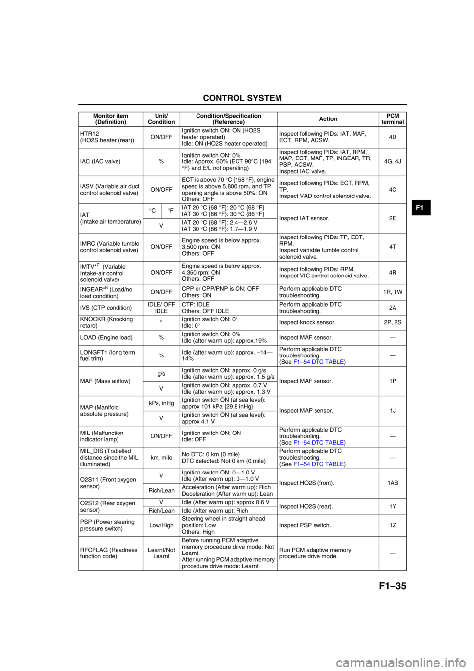
HTR12
(HO2S heater (rear))ON/OFFIgnition switch ON: ON (HO2S
heater operated)
Idle: ON (HO2S heater operated)Inspect following PIDs: IAT, MAF,
ECT, RPM, ACSW.4D
IAC (IAC valve) %Ignition switch ON: 0%
Idle: Approx. 60% (ECT 90°C {194
°F} and E/L not operating) Inspect following PIDs: IAT, RPM,
MAP, ECT, MAF, TP, INGEAR, TR,
PSP, ACSW.
Inspect IAC valve.4G, 4J
IASV (Variable air duct
control solenoid valve)ON/OFFECT is above 70 °C {158 °F}, engine
speed is above 5,800 rpm, and TP
opening angle is above 50%: ON
Others: OFFInspect following PIDs: ECT, RPM,
TP.
Inspect VAD control solenoid valve.4C
IAT
(Intake air temperature)°C°FIAT 20 °C {68 °F}: 20 °C {68 °F}
IAT 30 °C {86 °F}: 30 °C {86 °F}
Inspect IAT sensor. 2E
VIAT 20 °C {68 °F}: 2.4—2.6 V
IAT 30 °C {86 °F}: 1.7—1.9 V
IMRC (Variable tumble
control solenoid valve)ON/OFFEngine speed is below approx.
3,500 rpm: ON
Others: OFFInspect following PIDs: TP, ECT,
RPM.
Inspect variable tumble control
solenoid valve.4T
IMTV*
7 (Variable
Intake-air control
solenoid valve)ON/OFFEngine speed is below approx.
4,350 rpm: ON
Others: OFFInspect following PIDs: RPM.
Inspect VIC control solenoid valve.4R
INGEAR*
8 (Load/no
load condition)ON/OFFCPP or CPP/PNP is ON: OFF
Others: ONPerform applicable DTC
troubleshooting.1R, 1W
IVS (CTP condition)IDLE/ OFF
IDLECTP: IDLE
Others: OFF IDLEPerform applicable DTC
troubleshooting.2A
KNOCKR (Knocking
retard)°Ignition switch ON: 0°
Idle: 0°Inspect knock sensor. 2P, 2S
LOAD (Engine load) %Ignition switch ON: 0%
Idle (after warm up): approx.19%Inspect MAF sensor.—
LONGFT1 (long term
fuel trim)%Idle (after warm up): approx. –14—
14%Perform applicable DTC
troubleshooting.
(See F1–54 DTC TABLE)—
MAF (Mass airflow)g/sIgnition switch ON: approx. 0 g/s
Idle (after warm up): approx. 1.5 g/s
Inspect MAF sensor. 1P
VIgnition switch ON: approx. 0.7 V
Idle (after warm up): approx. 1.3 V
MAP (Manifold
absolute pressure)kPa, inHgIgnition switch ON (at sea level):
approx 101 kPa {29.8 inHg}
Inspect MAP sensor. 1J
VIgnition switch ON (at sea level):
approx 4.1 V
MIL (Malfunction
indicator lamp)ON/OFFIgnition switch ON: ON
Idle: OFFPerform applicable DTC
troubleshooting.
(See F1–54 DTC TABLE)—
MIL_DIS (Trabelled
distance since the MIL
illuminated)km, mileNo DTC: 0 km {0 mile}
DTC detected: Not 0 km {0 mile}Perform applicable DTC
troubleshooting.
(See F1–54 DTC TABLE)—
O2S11 (Front oxygen
sensor)VIgnition switch ON: 0—1.0 V
Idle (After warm up): 0—1.0 V
Inspect HO2S (front). 1AB
Rich/LeanAcceleration (After warm up): Rich
Deceleration (After warm up): Lean
O2S12 (Rear oxygen
sensor)V Idle (After warm up): approx 0.6 V
Inspect HO2S (rear). 1Y
Rich/Lean Idle (After warm up): Rich
PSP (Power steering
pressure switch)Low/HighSteering wheel in straight ahead
position: Low
Others: HighInspect PSP switch. 1Z
RFCFLAG (Readness
function code)Learnt/Not
LearntBefore running PCM adaptive
memory procedure drive mode: Not
Learnt
After running PCM adaptive memory
procedure drive mode: LearntRun PCM adaptive memory
procedure drive mode.— Monitor item
(Definition)Unit/
ConditionCondition/Specification
(Reference)ActionPCM
terminal
Page 126 of 909

F1–38
CONTROL SYSTEM
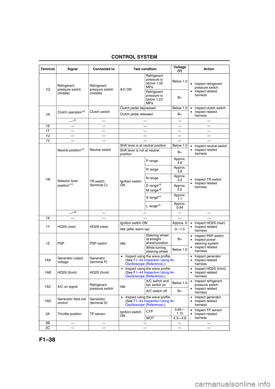
1QRefrigerant
pressure switch
(middle)Refrigerant
pressure switch
(middle)A/C ONRefrigerant
pressure is
above 1.52
MPaBelow 1.0
•Inspect refrigerant
pressure switch
•Inspect related
harness Refrigerant
pressure is
below 1.23
MPaB+
1RClutch operation*
2Clutch switchClutch pedal depressed Below 1.0•Inspect clutch switch
•Inspect related
harness Clutch pedal released B+
—*
3————
1S—— — ——
1T—— — ——
1U—— — ——
1V—— — ——
1WNeutral position*
2Neutral switchShift lever is at neutral position Below 1.0
•Inspect neutral switch
•Inspect related
harness Shift lever is not at neutral
positionB+
Selector lever
position*
11TR switch
(terminal C)Ignition switch
ONP rangeApprox.
4.6
•Inspect TR switch
•Inspect related
harness R rangeApprox.
3.9
N rangeApprox.
3.2
D range*4
M range*5Approx.
2.5
S range*
4Approx.
1.7
L range*
4Approx.
0.94
—*
12————
1X—— — ——
1Y HO2S (rear) HO2S (rear)Ignition switch ON Approx. 0•Inspect HO2S (rear)
•Inspect related
harness Idle (after warm up) 0—1.0
1Z PSP PSP switch IdleSteering wheel
at straight
ahead positionB+•Inspect PSP switch
•Inspect power
steering system
•Inspect related
harness While turning
steering wheelBelow 1.0
1AAGenerator output
voltageGenerator
(terminal P)•Inspect using the wave profile.
(See F1–44 Inspection Using An
Oscilloscope (Reference).)•Inspect generator
•Inspect related
harness
1AB HO2S (front) HO2S (front)•Inspect using the wave profile.
(See F1–44 Inspection Using An
Oscilloscope (Reference).)•Inspect HO2S (front)
•Inspect related
harness
1AC A/C on signalRefrigerant
pressure switchIdleA/C switch and
fan switch onBelow 1.0•Inspect refrigerant
pressure switch
•Inspect related
harness A/C switch off B+
1ADGenerator field coil
controlGenerator
(terminal D)•Inspect using the wave profile.
(See F1–44 Inspection Using An
Oscilloscope (Reference).)•Inspect generator
•Inspect related
harness
2A Throttle position TP sensorIgnition switch
ONCTP0.65—
1.15•Inspect TP sensor
•Inspect related
harness
WOT 4.3—4.8
2B—— — ——
2C—— — —— Terminal Signal Connected to Test conditionVoltage
(V)Action
Page 324 of 909

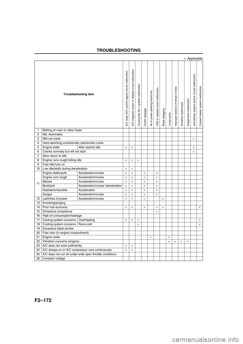
F2–172
TROUBLESHOOTING
×: Applicable
End Of Sie
Troubleshooting item
1 Melting of main or other fuses
2 MIL illuminates
3 Will not crank×
4 Hard start/long crank/erratic start/erratic crank
5 Engine stalls After start/at idle×× ×
6 Cranks normally but will not start×
7 Slow return to idle
8 Engine runs rough/rolling idle×××
9 Fast idle/runs on
10 Low idle/stalls during deceleration××
11Engine stalls/quits Acceleration/cruise××××
Engine runs rough Acceleration/cruise××××
Misses Acceleration/cruise××××
Buck/jerk Acceleration/cruise/ deceleration××××
Hesitation/stumble Acceleration××××
Surges Acceleration/cruise××××
12 Lack/loss of power Acceleration/cruise×× × ×
13 Knocking/pinging
14 Poor fuel economy××××× ×
15 Emissions compliance×
16 High oil consumption/leakage
17 Cooling system concerns Overheating××× ×
18 Cooling system concerns Runs cold××
19 Excessive black smoke
20 Fuel odor (in engine compartment)
21 Engine noise××
22 Vibration concerns (engine)××××
23 A/C does not work sufficiently××
24 A/C always on or A/C compressor runs continuously××
25 A/C does not cut off under wide open throttle conditions
26 Constant voltage
A/C relay (A/C control siganl) circuit malfunctionA/C magnetic clutch or related circuit malfunctionCooling fan No.1 system malfunctionClutch slippageAir in power steering fuluid lineVSS or related circuit malfunctionBrake draggingLoose partsImproper balance of wheel or tiresDriveline malfunctionSuspension malfunctionImmobilizer system and/or circuit malfunctionCoolant heater system malfunction
Page 409 of 909

MANUAL TRANSAXLE
J2–7
J2
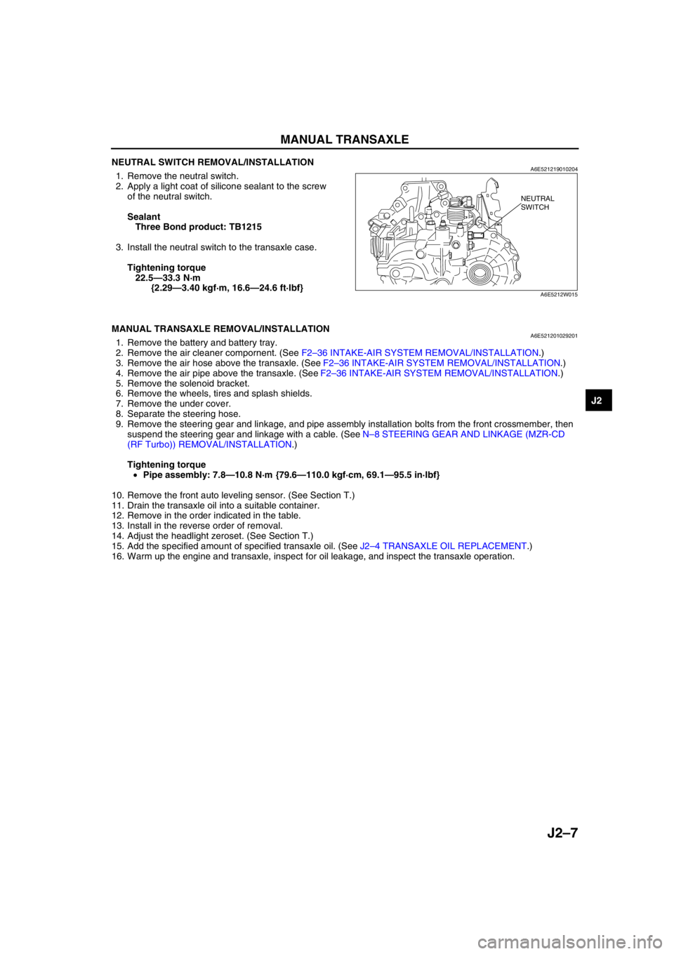
NEUTRAL SWITCH REMOVAL/INSTALLATIONA6E5212190102041. Remove the neutral switch.
2. Apply a light coat of silicone sealant to the screw
of the neutral switch.
Sealant
Three Bond product: TB1215
3. Install the neutral switch to the transaxle case.
Tightening torque
22.5—33.3 N·m
{2.29—3.40 kgf·m, 16.6—24.6 ft·lbf}
End Of Sie
MANUAL TRANSAXLE REMOVAL/INSTALLATIONA6E5212010292011. Remove the battery and battery tray.
2. Remove the air cleaner compornent. (See F2–36 INTAKE-AIR SYSTEM REMOVAL/INSTALLATION.)
3. Remove the air hose above the transaxle. (See F2–36 INTAKE-AIR SYSTEM REMOVAL/INSTALLATION.)
4. Remove the air pipe above the transaxle. (See F2–36 INTAKE-AIR SYSTEM REMOVAL/INSTALLATION.)
5. Remove the solenoid bracket.
6. Remove the wheels, tires and splash shields.
7. Remove the under cover.
8. Separate the steering hose.
9. Remove the steering gear and linkage, and pipe assembly installation bolts from the front crossmember, then
suspend the steering gear and linkage with a cable. (See N–8 STEERING GEAR AND LINKAGE (MZR-CD
(RF Turbo)) REMOVAL/INSTALLATION.)
Tightening torque
•Pipe assembly: 7.8—10.8 N·m {79.6—110.0 kgf·cm, 69.1—95.5 in·lbf}
10. Remove the front auto leveling sensor. (See Section T.)
11. Drain the transaxle oil into a suitable container.
12. Remove in the order indicated in the table.
13. Install in the reverse order of removal.
14. Adjust the headlight zeroset. (See Section T.)
15. Add the specified amount of specified transaxle oil. (See J2–4 TRANSAXLE OIL REPLACEMENT.)
16. Warm up the engine and transaxle, inspect for oil leakage, and inspect the transaxle operation.
NEUTRAL
SWITCH
A6E5212W015
Page 716 of 909

N–2
OUTLINE
OUTLINE OF CONSTRUCTIONA6E660201036201•The construction and operation of the steering system is essentially carried over from that of the current
Mazda6 (GG), except for the following features. (See Mazda6 Training Manual 3359-1*-02C.)
• Due to the addition of the MZR-CD (RF Turbo) engine, a gear-driven power steering oil pump has been
adopted. The operation of the oil pump is the same as that of the current Mazda6 (GG).
• The disassembly/assembly procedures for the steering gear and linkage of the newly equipped MZR-CD (RF
Turbo) engine, wagon and 4WD models are the same as that of the current Mazda6 (GG).
End Of Sie
FEATURESA6E660201036202Improved Steering Feel
• The fluid pressure characteristics of the power steering system has been optimized (MZR-CD (RF Turbo) and
4WD models).
End Of Sie
SPECIFICATIONSA6E660201036203
* : When reservoir tank is at maximum volume
Bold frame:New specifications
End Of Sie
OUTLINE
Item New Mazda6
(GG) (4SD, 5HB) New Mazda6 (GY) (Wagon) Current Mazda6
(GG) (4SD, 5HB)
Drive train 2WD 4WD 2WD
Steering
wheel Outer diameter
370 {14.6}
(mm {in})
Lock-to-lock 18 inch wheel specification vehicles: 2.65
Except for above: 2.75 2.75
(turns)
Steering gear
and linkage Type Rack-and-pinion
Rack stroke 18 inch wheel specification vehicles:
141.6—143.6 {5.57—5.65}
Except for above:146.8—148.8
{5.78—5.85} 146.8—148.8 {5.78—5.85}
(mm {in})
Steering
column and
shaft Shaft type Collapsible
Joint type 2-cross joint
Amount of tilt
45 {1.8}
(mm {in})
Amount of telescope
(If equipped) 50 {2.0}
(mm {in})
Powe r
steering
system Power assist type Engine speed sensing
Pow er
steering
fluid
Ty p e
M-
III or equivalent (e.g. Dexron®II)
Fluid capacity
*
(approximate
quantity) MTX (except MZR-CD (RF Turbo)):
0.80 {0.85, 0.70}
ATX: 0.87 {0.92, 0.77} MZR-CD (RF Turbo):
0.86 {0.91, 0.76} 0.89 {0.94, 0.78}
MTX:
0.80 {0.85, 0.70}
AT X :
0.87 {0.92, 0.77}
(L {US qt, Imp qt})
Page 717 of 909

OUTLINE
N–3
N
STRUCTURAL VIEWA6E660201036204MZR-CD (RF Turbo)
.
7
6
7
6
5
5
3
1
2
4
A6E63162001
1L.H.D.
2 R.H.D.
3 Steering wheel
4 Steering column and shaft5 Steering gear
6 Power steering oil pump
7 Fluid reservoir
Page 718 of 909

N–4
OUTLINE
4WD
.
End Of Sie
8
7
5
4
3
1
2
6
5
6
8
7
A6E63162002
1 L.H.D.
2 R.H.D.
3 Steering wheel
4 Steering column and shaft5 Steering gear
6 Power steering oil pump
7 Fluid reservoir
8 Cooling pipe
Page 720 of 909

N–6
ENGINE SPEED SENSING POWER STEERING
POWER STEERING FLUID INSPECTIONA6E661432040201Fluid Level Inspection
1. Inspect the power steering fluid level.
•Add fluid to the specified level as necessary.
Fluid specification
ATF M-III or equivalent (e.g. Dexron
®II)
Fluid Leakage Inspection
Caution
•If the steering wheel is kept in the fully turned position for more than 5 seconds, the fluid
temperature will rise excessively and adversely affect the oil pump.
1. Start the engine and let it idle.
2. Turn the steering wheel fully to the left and right to apply fluid pressure.
Note
•The points where fluid leakage may occur are indicated in the figure.
3. Inspect for fluid leakage.
•If fluid leakage is found, replace the related pipe or hose.
ENGINE SPEED SENSING POWER STEERING
L.H.D.
ATX
MTX
R.H.D.
ATX
MTX MZR-CD (RF Turbo)
EXCEPT MZR-CD (RF Turbo)L.H.D
R.H.D
A6E66142001