spare wheel MAZDA 6 2002 Workshop Manual Suplement
[x] Cancel search | Manufacturer: MAZDA, Model Year: 2002, Model line: 6, Model: MAZDA 6 2002Pages: 909, PDF Size: 17.16 MB
Page 22 of 909
GI–18
SCHEDULED MAINTENANCE
End Of Sie
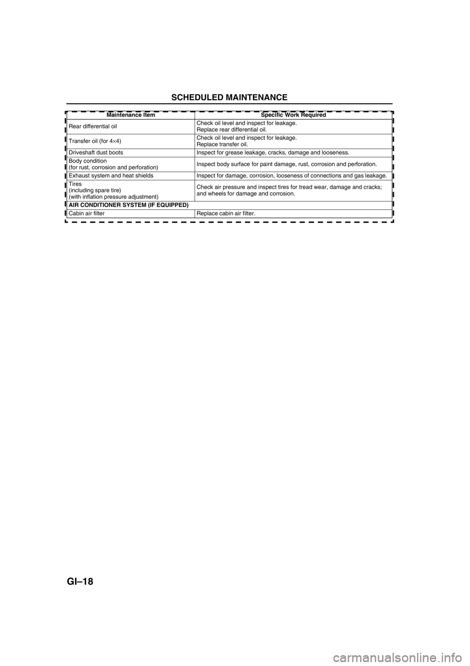
Rear differential oilCheck oil level and inspect for leakage.
Replace rear differential oil.
Transfer oil (for 4×4)Check oil level and inspect for leakage.
Replace transfer oil.
Driveshaft dust boots Inspect for grease leakage, cracks, damage and looseness.
Body condition
(for rust, corrosion and perforation)Inspect body surface for paint damage, rust, corrosion and perforation.
Exhaust system and heat shields Inspect for damage, corrosion, looseness of connections and gas leakage.
Tires
(including spare tire)
(with inflation pressure adjustment)Check air pressure and inspect tires for tread wear, damage and cracks;
and wheels for damage and corrosion.
AIR CONDITIONER SYSTEM (IF EQUIPPED)
Cabin air filter Replace cabin air filter.Maintenance Item Specific Work Required
Page 651 of 909
GENERAL PROCEDURES
M–21
M
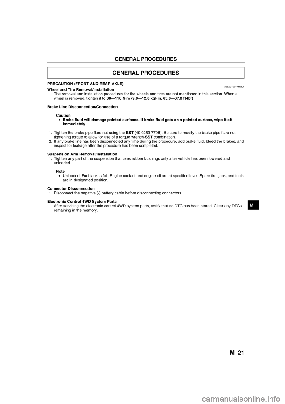
PRECAUTION (FRONT AND REAR AXLE)A6E631001018201Wheel and Tire Removal/Installation
1. The removal and installation procedures for the wheels and tires are not mentioned in this section. When a
wheel is removed, tighten it to 88—118 N·m {9.0—12.0 kgf·m, 65.0—87.0 ft·lbf}
Brake Line Disconnection/Connection
Caution
•Brake fluid will damage painted surfaces. If brake fluid gets on a painted surface, wipe it off
immediately.
1. Tighten the brake pipe flare nut using the SST (49 0259 770B). Be sure to modify the brake pipe flare nut
tightening torque to allow for use of a torque wrench-SST combination.
2. If any brake line has been disconnected any time during the procedure, add brake fluid, bleed the brakes, and
inspect for leakage after the procedure has been completed.
Suspension Arm Removal/Installation
1. Tighten any part of the suspension that uses rubber bushings only after vehicle has been lowered and
unloaded.
Note
•Unloaded: Fuel tank is full. Engine coolant and engine oil are at specified level. Spare tire, jack, and tools
are in designated position.
Connector Disconnection
1. Disconnect the negative (-) battery cable before disconnecting connectors.
Electronic Control 4WD System Parts
1. After servicing the electronic control 4WD system parts, verify that no DTC has been stored. Clear any DTCs
remaining in the memory.
End Of Sie
GENERAL PROCEDURES
Page 765 of 909
OUTLINE
R–3
R
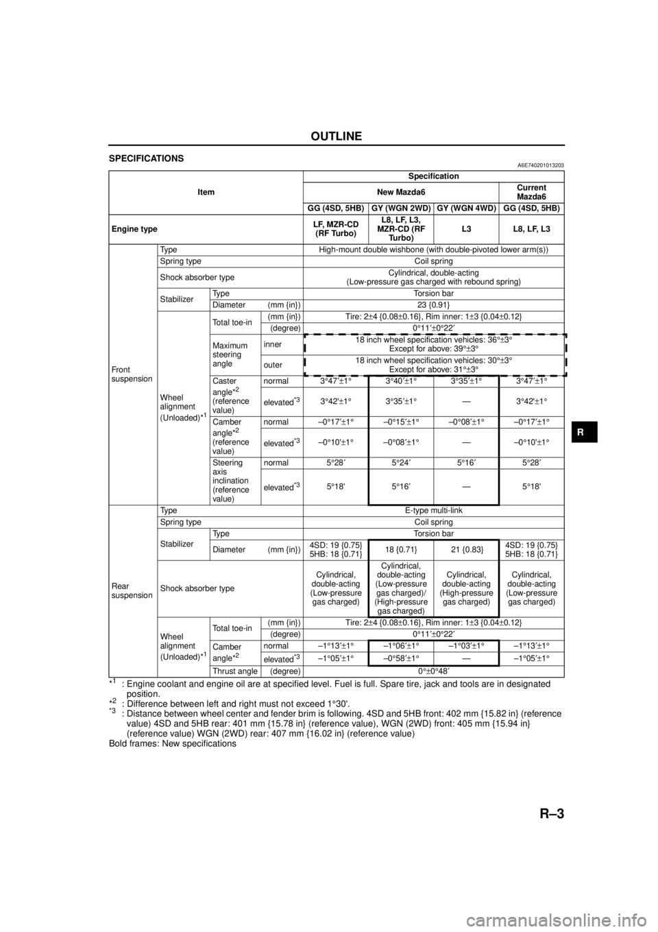
SPECIFICATIONSA6E740201013203
*1: Engine coolant and engine oil are at specified level. Fuel is full. Spare tire, jack and tools are in designated position.
*
2: Difference between left and right must not exceed 1 °30'.*3: Distance between wheel center and fender brim is following. 4SD and 5HB front: 402 mm {15.82 in} (reference
value) 4SD and 5HB rear: 401 mm {15.78 in} (reference value), WGN (2WD) front: 405 mm {15.94 in}
(reference value) WGN (2WD) rear: 407 mm {16.02 in} (reference value)
Bold frames: New specifications
End Of Sie
Item Specification
New Mazda6 Current
Mazda6
GG (4SD, 5HB) GY (WGN 2WD) GY (WGN 4WD) GG (4SD, 5HB)
Engine type LF, MZR-CD
(RF Turbo) L8, LF, L3,
MZR-CD (RF Turbo) L3 L8, LF, L3
Fr o nt
suspension Type High-mount double wishbone (with double-pivoted lower arm(s))
Spring type Coil spring
Shock absorber type
Cylindrical, double-acting
(Low-pressure gas charged with rebound spring)
Stabilizer Type Torsion bar
Diameter (mm {in}) 23 {0.91}
Wheel
alignment
(Unloaded)*
1
Total toe-in (mm {in}) Tire: 2
±4 {0.08 ±0.16}, Rim inner: 1 ±3 {0.04 ±0.12}
(degree) 0 °11 ′±0°22 ′
Maximum
steering
angle inner
18 inch wheel specification vehicles: 36
°±3°
Except for above: 39 °±3°
outer 18 inch wheel specification vehicles: 30
°±3°
Except for above: 31 °±3°
Caster
angle*
2
(reference
value) normal 3
°47 ′±1° 3°40 ′±1° 3°35 ′±1° 3°47 ′±1°
elevated*33 °42' ±1° 3°35 ′±1° —3 °42' ±1 °
Camber
angle*
2
(reference
value) normal –0
°17 ′±1° –0°15 ′±1° –0°08 ′±1° –0°17 ′±1°
elevated*3–0 °10' ±1° –0°08 ′±1° —–0 °10' ±1°
Steering
axis
inclination
(reference
value) normal 5
°28 ′ 5°24 ′ 5°16 ′ 5°28 ′
elevated
*35 °18' 5 °16 ′ —5 °18'
Rear
suspension Type E-type multi-link
Spring type Coil spring
Stabilizer
Type Torsion bar
Diameter (mm {in})
4SD: 19 {0.75}
5HB: 18 {0.71}18 {0.71} 21 {0.83}
4SD: 19 {0.75}
5HB: 18 {0.71}
Shock absorber type Cylindrical,
double-acting
(Low-pressure gas charged) Cylindrical,
double-acting
(Low-pressure gas charged)/
(High-pressure
gas charged) Cylindrical,
double-acting
(High-pressure gas charged) Cylindrical,
double-acting
(Low-pressure gas charged)
Wheel
alignment
(Unloaded)*
1
Total toe-in (mm {in}) Tire: 2
±4 {0.08 ±0.16}, Rim inner: 1 ±3 {0.04 ±0.12}
(degree) 0 °11 ′±0°22 ′
Camber
angle*
2
normal –1 °13 ′±1° –1°06 ′±1° –1°03 ′±1° –1°13 ′±1°
elevated
*3–1 °05 ′±1° –0°58 ′±1° —–1 °05 ′±1°
Thrust angle (degree) 0 °±0°48 ′
Page 770 of 909
R–8
WHEEL ALIGNMENT
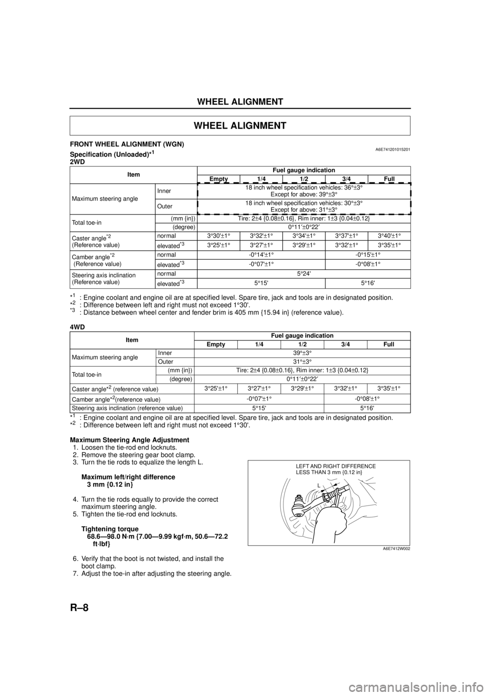
FRONT WHEEL ALIGNMENT (WGN)A6E741201015201Specification (Unloaded)*1
2WD
*
1: Engine coolant and engine oil are at specified level. Spare tire, jack and tools are in designated position.
*2: Difference between left and right must not exceed 1 °30'.*3: Distance between wheel center and fender brim is 405 mm {15.94 in} (reference value).
4WD
*
1: Engine coolant and engine oil are at specified level. Spare tire, jack and tools are in designated position.
*2: Difference between left and right must not exceed 1 °30'.
Maximum Steering Angle Adjustment 1. Loosen the tie-rod end locknuts.
2. Remove the steering gear boot clamp.
3. Turn the tie rods to equalize the length L.
Maximum left/right difference3 mm {0.12 in}
4. Turn the tie rods equally to provide the correct maximum steering angle.
5. Tighten the tie-rod end locknuts.
Tightening torque68.6—98.0 N·m {7.00—9.99 kgf·m, 50.6—72.2 ft·lbf}
6. Verify that the boot is not twisted, and install the boot clamp.
7. Adjust the toe-in after adjusting the steering angle.
WHEEL ALIGNMENT
Item Fuel gauge indication
Empty 1/4 1/2 3/4 Full
Maximum steering angle Inner
18 inch wheel specification vehicles: 36
°±3°
Except for above: 39 °±3°
Outer 18 inch wheel specification vehicles: 30
°±3°
Except for above: 31 °±3°
Total toe-in (mm {in}) Tire: 2
±4 {0.08 ±0.16}, Rim inner: 1 ±3 {0.04 ±0.12}
(degree) 0 °11 ′±0°22 ′
Caster angle
*2
(Reference value) normal 3
°30' ±1 ° 3°32' ±1 ° 3°34' ±1° 3°37' ±1° 3°40' ±1 °
elevated*33 °25' ±1 ° 3°27' ±1 ° 3°29' ±1° 3°32' ±1° 3°35' ±1 °
Camber angle
*2
(Reference value) normal -0
°14' ±1 ° -0°15' ±1°
elevated*3-0 °07' ±1 ° -0°08' ±1°
Steering axis inclination
(Reference value) normal 5
°24'
elevated
*35 °15' 5 °16'
Item Fuel gauge indication
Empty 1/4 1/2 3/4 Full
Maximum steering angle Inner 39
°±3°
Outer 31 °±3°
Total toe-in (mm {in}) Tire: 2
±4 {0.08 ±0.16}, Rim inner: 1 ±3 {0.04 ±0.12}
(degree) 0 °11 ′±0°22 ′
Caster angle*
2 (reference value) 3
°25' ±1 ° 3°27' ±1 ° 3°29' ±1 ° 3°32' ±1 ° 3°35' ±1 °
Camber angle*
2(reference value) -0
°07' ±1 ° -0°08' ±1°
Steering axis inclination (reference value) 5 °15' 5 °16'
LEFT AND RIGHT DIFFERENCE
L
LESS THAN 3 mm {0.12 in}
A6E7412W002
Page 771 of 909
WHEEL ALIGNMENT
R–9
R
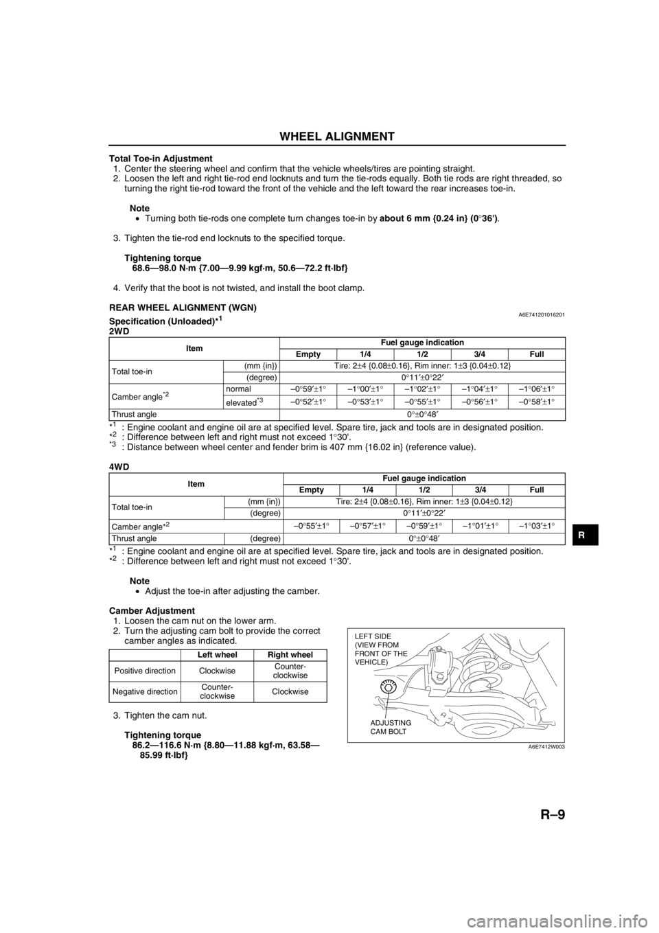
Total Toe-in Adjustment
1. Center the steering wheel and confirm that the vehicle wheels/tires are pointing straight.
2. Loosen the left and right tie-rod end locknuts and turn the tie-rods equally. Both tie rods are right threaded, so
turning the right tie-rod toward the front of the vehicle and the left toward the rear increases toe-in.
Note
•Turning both tie-rods one complete turn changes toe-in by about 6 mm {0.24 in} (0°36').
3. Tighten the tie-rod end locknuts to the specified torque.
Tightening torque
68.6—98.0 N·m {7.00—9.99 kgf·m, 50.6—72.2 ft·lbf}
4. Verify that the boot is not twisted, and install the boot clamp.
End Of Sie
REAR WHEEL ALIGNMENT (WGN)A6E741201016201Specification (Unloaded)*1
2WD
*
1: Engine coolant and engine oil are at specified level. Spare tire, jack and tools are in designated position.
*2: Difference between left and right must not exceed 1°30'.*3: Distance between wheel center and fender brim is 407 mm {16.02 in} (reference value).
4WD
*
1: Engine coolant and engine oil are at specified level. Spare tire, jack and tools are in designated position.
*2: Difference between left and right must not exceed 1°30'.
Note
•Adjust the toe-in after adjusting the camber.
Camber Adjustment
1. Loosen the cam nut on the lower arm.
2. Turn the adjusting cam bolt to provide the correct
camber angles as indicated.
3. Tighten the cam nut.
Tightening torque
86.2—116.6 N·m {8.80—11.88 kgf·m, 63.58—
85.99 ft·lbf}
ItemFuel gauge indication
Empty 1/4 1/2 3/4 Full
Total toe-in(mm {in}) Tire: 2±4 {0.08±0.16}, Rim inner: 1±3 {0.04±0.12}
(degree) 0°11′±0°22′
Camber angle
*2 normal–0°59′±1°–1°00′±1°–1°02′±1°–1°04′±1°–1°06′±1°
elevated
*3–0°52′±1°–0°53′±1°–0°55′±1°–0°56′±1°–0°58′±1°
Thrust angle 0°±0°48′
ItemFuel gauge indication
Empty 1/4 1/2 3/4 Full
Total toe-in(mm {in}) Tire: 2±4 {0.08±0.16}, Rim inner: 1±3 {0.04±0.12}
(degree) 0°11′±0°22′
Camber angle*
2 –0°55′±1°–0°57′±1°–0°59′±1°–1°01′±1°–1°03′±1°
Thrust angle (degree) 0°±0°48′
Left wheel Right wheel
Positive direction ClockwiseCounter-
clockwise
Negative directionCounter-
clockwiseClockwise
LEFT SIDE
(VIEW FROM
FRONT OF THE
VEHICLE)
ADJUSTING
CAM BOLT
A6E7412W003
Page 899 of 909

TECHNICAL DATA
TD–7
TD
BRAKING SYSTEMA6E931001020201
End Of Sie
SUSPENSIONA6E931001013201Suspension
WGN (2WD)
*1: Engine coolant and engine oil are at specified level. Spare tire, jack, and tools are in designated position. Adjust to the median when carrying out wheel alignment.
*2: Difference between left and right must not exceed 1 ° 30 ′.*3: Distance between wheel center and fender brim is following. Front: 405 mm {15.94 in} (reference value) Rear:
407 mm {16.02 in} (reference value)
WGN (4WD)
*1: Engine coolant and engine oil are at specified level. Spare tire, jack, and tools are in designated position. Adjust to the median when carrying out wheel alignment.
*2: Difference between left and right must not exceed 1 ° 30 ′.
Item Specification
CONVENTIONAL BRAKE SYSTEM
Front disc
brake Minimum disc pad
thickness
(mm {in})L8, LF (GCC specs.): 22 mm {0.87 in}
LF (European (L.H.D. U.K.) specs.), L3, MZR-CD (RF Turbo):
23 mm {0.91 in}
Minimum disc plate
thickness (mm {in})L8, LF (GCC specs.): 22.8 mm {0.90 in}
LF (European (L.H.D. U.K.) specs.), L3, MZR-CD (RF Turbo): 23.8 mm {0.94 in}
Item Fuel gauge indication
Empty 1/4 1/2 3/4 Full
Fr o nt wh ee l
alignment
(Unloaded)
*1
Maximum steering
angle Inner
18 inch wheel specification vehicles: 36
°±3°
Except for above: 39 °±3°
Outer 18 inch wheel specification vehicles: 30
°±3°
Except for above: 31 °±3°
Total toe-in (mm {in}) Tire: 2
±4 {0.08 ±0.16}, Rim inner: 1 ±3 {0.04 ±0.12}
(degree) 0 °11 ′±0°22 ′
Caster angle
*2
(Reference value) normal 3
°30' ±1 ° 3°32' ±1 ° 3°34' ±1 ° 3°37' ±1 ° 3°40' ±1°
elevated*33 °25' ±1 ° 3°27' ±1 ° 3°29' ±1 ° 3°32' ±1 ° 3°35' ±1°
Camber angle
*2
(Reference value) normal –0
°14' ±1 ° –0°15' ±1°
elevated*3–0 °07' ±1 ° –0°08' ±1°
Steering axis inclination
(Reference value) normal 5
°24'
elevated
*35 °15' 5 °16'
Rear wheel
alignment
(Unloaded)
*1
Total toe-in (mm {in}) Tire: 2
±4 {0.08 ±0.16}, Rim inner: 1 ±3 {0.04 ±0.12}
(degree) 0 °11 ′±0°22 ′
Camber angle
*2 normal –0 °59 ′±1° –1°00 ′±1° –1°02 ′±1° –1°04 ′±1° –1°06 ′±1°
elevated
*3–0 °52 ′±1° –0°53 ′±1° –0°55 ′±1° –0°56 ′±1° –0°58 ′±1°
Thrust angle 0 °±0°48 ′
Item Fuel gauge indication
Empty 1/4 1/2 3/4 Full
Fr o nt wh ee l
alignment
(Unloaded)
*1
Maximum steering
angle Inner 39
°±3°
Outer 31 °±3°
Total toe-in (mm {in}) Tire: 2
±4 {0.08 ±0.16}, Rim inner: 1 ±3 {0.04 ±0.12}
(degree) 0 °11 ′±0°22 ′
Caster angle
*2 (Reference value) 3
°25' ±1 ° 3°27' ±1 ° 3°29' ±1 ° 3°32' ±1 ° 3°35' ±1°
Camber angle
*2 (Reference value) –0
°07' ±1 ° –0°08' ±1°
Steering axis inclination
(Reference value) 5
°15' 5 °16'
Rear wheel
alignment
(Unloaded)
*1
Total toe-in (mm {in}) Tire: 2
±4 {0.08 ±0.16}, Rim inner: 1 ±3 {0.04 ±0.12}
(degree) 0 °11 ′±0°22 ′
Camber angle
*2 –0 °55 ′±1° –0°57 ′±1° –0°59 ′±1° –1°01 ′±1° –1°03 ′±1°
Thrust angle 0 °±0°48 ′
Page 900 of 909

TD–8
TECHNICAL DATA
Wheel and Tires
*
1: Total weight exceeds 160 g {5.65 oz}.
*2: One balance weight: 60 g {2.12 oz} max. If the total weight exceeds 100 g {3.53 oz} on one side, rebalance after moving the tire around on the rim. Do not use 3 or more balance weights.
End Of Sie
BODY ELECTRICAL SYSTEMA6E931001047201
End Of Sie
Item Specification
Standard tire and wheel
Wheel Size 15
× 6JJ 16 × 7JJ 17 × 7JJ 18 × 7J
Offset (mm {in}) 50 {1.97} 55 {2.17} 55 {2.17}
Pitch circle diameter (mm {in}) 114.3 {4.50} 114.3 {4.50}
Material Steel Aluminum alloy Aluminum alloy
Tire Size 195/65R15 91V 205/55R16 91V
215/45R17
87W 215/45R17
91W
(reinforced) 215/45R18 89W
Air pressure
(kPa {kgf/
cm
2, psi}) Front
Up to 4
persons
220 {2.2, 32} 2WD: 230
{2.3, 33}
4WD: 250 {2.5, 36} 220 {2.2, 32}
Full load 240 {2.4, 35} 2WD: 240
{2.4, 35}
4WD: 250 {2.5, 36} 240 {2.4, 35}
Rear Up to 4
persons
220 {2.2, 32} 2WD: 230
{2.3, 33}
4WD: 250 {2.5, 36} 220 {2.2, 32}
Full load 300 {3.1, 44} 270 {2.8, 39} 270 {2.8, 39}
Remaining tread (mm {in}) 1.6 {0.06} 1.6 {0.06}
Wheel
and
tire Wheel and tire
runout
Radial
direction
1.5 {0.06} max. 1.5 {0.06} max.
(mm {in}) Lateral direction 2.5 {0.10} max. 2.0 {0.08} max. 2.0 {0.08} max.
Wheel imbalance (g {oz}) Knock-type*
2:
9 {0.32} max. Adhesive-type*
1:
13 {0.46} max.
Knock-type*
2:
8 {0.28} max. Adhesive-type*
1:
11 {0.39} max.
Knock-type*
2:
7 {0.25} max. Adhesive-type*
1:
10 {0.35} max.
Knock-type*
2:
6 {0.21} max.
Temporary spare tire
Wheel Size 15
×4T
Offset (mm {in}) 40 {1.57}
Pitch circle diameter (mm {in}) 114.3 {4.50}
Material Steel
Tire Size T115/70 D15 T135/90 D15
Air pressure
(kPa {kgf/cm
2,
psi}) 420 {4.2, 60}
Wheel
and
tire Wheel and tire
runout
Radial
direction
2.0 {0.08} max.
(mm {in}) Lateral direction 2.5 {0.10} max.
Item Specifications
Exterior light bulb capacity (W) High-mount brake
lightWGNIn-vehicle-type 18.4
× 1
Rear spoiler
type 4
× 1 (LED)
Interior light bulb capacity (W) Cargo compartment light 10 × 1