wheel alignment MAZDA 6 2002 Workshop Manual Suplement
[x] Cancel search | Manufacturer: MAZDA, Model Year: 2002, Model line: 6, Model: MAZDA 6 2002Pages: 909, PDF Size: 17.16 MB
Page 402 of 909

H–8
CLUTCH UNIT, FLYWHEEL
4. Rotate the flywheel and check for misaligned
diaphragm spring fingers.
•If not as specified, replace the clutch cover.
Misalignment
0.6 mm {0.024 in} max.
End Of Sie
FLYWHEEL INSPECTION (A65M-R MANUAL TRANSAXLE MODELS)A6E4922115002011. Install a dial gauge on the cylinder block.
2. Measure the flywheel runout using a dial
indicator.
•If the runout is excessive, replace the
flywheel.
Runout
0.3 mm {0.012 in} max.
End Of Sie
A6E4920W016
FLYWHEEL
A6E4922W001
Page 712 of 909

M–82
TROUBLESHOOTING
FOREWORDA6E638027100202
End Of Sie
SYMPTOM TROUBLESHOOTINGA6E638027100203•Verify the symptoms, and perform troubleshooting according to the appropriate number.
End Of Sie
NO.1 FREQUENT FRONT WHEEL SLIPA6E638027100204
Warning
•During simulation driving, vehicle stability may decrease extremely and cause an accident. Be
sure to perform the simulation test driving in a safe area.
Malfunction vehicle delivered
Questionnaire
Verify malfunction symptoms
Symptom troubleshooting
Verify that malfunctions have been repaired
Troubleshooting completedConfirm all customer problems using a questionnaire.
Confirm malfunction on actual vehicle.
DTC inspection
Inspect for DTCs using WDS or equivalent.
Perform applicable troubleshooting inspection according to
diagnostic index.
A6E63802001
No. Symptom Description
1 Frequent front wheel slip Front wheels slip frequently during acceleration on low-friction road.
2
Tight corner braking effectBrakes seem to be applied during tight cornering while driving very
slowly on paved road.
3 Abnormal noise and/or vibration from
coupling unitThere is abnormal noise and/or vibration from coupling unit during
driving.
1 Frequent front wheel slip
[TROUBLESHOOTING HINTS]
•Tire traction performance is extremely poor for given road friction. (4WD system is normal.)
•Improper wheel alignment (4WD system is normal.)
•Rear differential oil temperature is extremely high (Fail-safe condition)
•Differential oil temperature sensor malfunction (Fail-safe condition)
•Compare slip frequency with another vehicle of the same model (under the same road conditions and tire traction
performance).
•Replace tires with others of the same model and perform test under the same road conditions to determine if the
malfunction was caused by tire traction performance.
•Coupling component malfunction
•4WD solenoid malfunction
Page 713 of 909
TROUBLESHOOTING
M–83
M
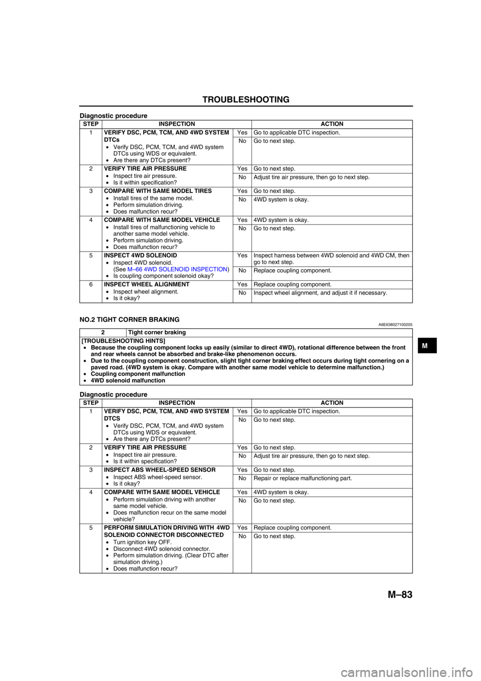
Diagnostic procedure
End Of Sie
NO.2 TIGHT CORNER BRAKINGA6E638027100205
Diagnostic procedure
STEP INSPECTION ACTION
1VERIFY DSC, PCM, TCM, AND 4WD SYSTEM
DTCs
•Verify DSC, PCM, TCM, and 4WD system
DTCs using WDS or equivalent.
•Are there any DTCs present?Yes Go to applicable DTC inspection.
No Go to next step.
2VERIFY TIRE AIR PRESSURE
•Inspect tire air pressure.
•Is it within specification?Yes Go to next step.
No Adjust tire air pressure, then go to next step.
3COMPARE WITH SAME MODEL TIRES
•Install tires of the same model.
•Perform simulation driving.
•Does malfunction recur?Yes Go to next step.
No 4WD system is okay.
4COMPARE WITH SAME MODEL VEHICLE
•Install tires of malfunctioning vehicle to
another same model vehicle.
•Perform simulation driving.
•Does malfunction recur?Yes 4WD system is okay.
No Go to next step.
5INSPECT 4WD SOLENOID
•Inspect 4WD solenoid.
(See M–66 4WD SOLENOID INSPECTION)
•Is coupling component solenoid okay?Yes Inspect harness between 4WD solenoid and 4WD CM, then
go to next step.
No Replace coupling component.
6INSPECT WHEEL ALIGNMENT
•Inspect wheel alignment.
•Is it okay?Yes Replace coupling component.
No Inspect wheel alignment, and adjust it if necessary.
2 Tight corner braking
[TROUBLESHOOTING HINTS]
•Because the coupling component locks up easily (similar to direct 4WD), rotational difference between the front
and rear wheels cannot be absorbed and brake-like phenomenon occurs.
•Due to the coupling component construction, slight tight corner braking effect occurs during tight cornering on a
paved road. (4WD system is okay. Compare with another same model vehicle to determine malfunction.)
•Coupling component malfunction
•4WD solenoid malfunction
STEP INSPECTION ACTION
1VERIFY DSC, PCM, TCM, AND 4WD SYSTEM
DTCS
•Verify DSC, PCM, TCM, and 4WD system
DTCs using WDS or equivalent.
•Are there any DTCs present?Yes Go to applicable DTC inspection.
No Go to next step.
2VERIFY TIRE AIR PRESSURE
•Inspect tire air pressure.
•Is it within specification?Yes Go to next step.
No Adjust tire air pressure, then go to next step.
3INSPECT ABS WHEEL-SPEED SENSOR
•Inspect ABS wheel-speed sensor.
•Is it okay?Yes Go to next step.
No Repair or replace malfunctioning part.
4COMPARE WITH SAME MODEL VEHICLE
•Perform simulation driving with another
same model vehicle.
•Does malfunction recur on the same model
vehicle?Yes 4WD system is okay.
No Go to next step.
5PERFORM SIMULATION DRIVING WITH 4WD
SOLENOID CONNECTOR DISCONNECTED
•Turn ignition key OFF.
•Disconnect 4WD solenoid connector.
•Perform simulation driving. (Clear DTC after
simulation driving.)
•Does malfunction recur?Yes Replace coupling component.
No Go to next step.
Page 763 of 909
R–1
R
RSUSPENSION
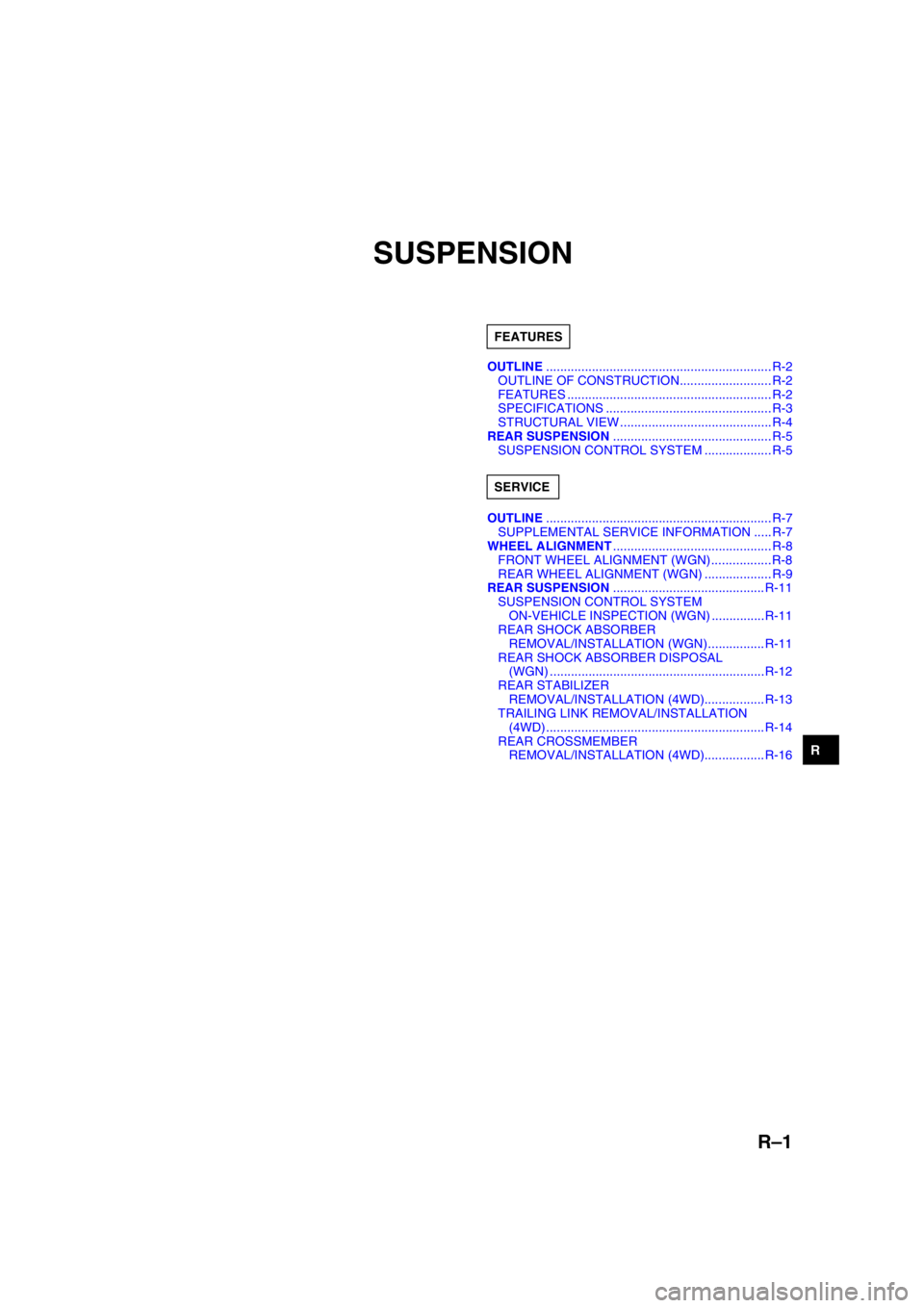
OUTLINE................................................................ R-2
OUTLINE OF CONSTRUCTION.......................... R-2
FEATURES .......................................................... R-2
SPECIFICATIONS ............................................... R-3
STRUCTURAL VIEW ...........................................R-4
REAR SUSPENSION............................................. R-5
SUSPENSION CONTROL SYSTEM ................... R-5
OUTLINE................................................................ R-7
SUPPLEMENTAL SERVICE INFORMATION .....R-7
WHEEL ALIGNMENT............................................. R-8
FRONT WHEEL ALIGNMENT (WGN).................R-8
REAR WHEEL ALIGNMENT (WGN) ................... R-9
REAR SUSPENSION........................................... R-11
SUSPENSION CONTROL SYSTEM
ON-VEHICLE INSPECTION (WGN) ...............R-11
REAR SHOCK ABSORBER
REMOVAL/INSTALLATION (WGN) ................ R-11
REAR SHOCK ABSORBER DISPOSAL
(WGN) .............................................................R-12
REAR STABILIZER
REMOVAL/INSTALLATION (4WD)................. R-13
TRAILING LINK REMOVAL/INSTALLATION
(4WD) .............................................................. R-14
REAR CROSSMEMBER
REMOVAL/INSTALLATION (4WD)................. R-16 FEATURES
SERVICE
Page 764 of 909

R–2
OUTLINE
OUTLINE OF CONSTRUCTIONA6E740201013201•The construction and operation of suspension system is essentially carried over from that of the current
Mazda6 (GG), except for the following features. (See Mazda6 Training Manual 3359-1*-02C.)
End Of Sie
FEATURESA6E740201013202Improved Handling Stability and Riding Comfort
•Wheel alignment has been set for WGN models.
•Rear stabilizer outer diameters are as follows:
WGN (2WD): 18 mm {0.71 in}
WGN (4WD): 21 mm {0.83 in}
•The suspension control system has been adopted as follows:
WGN (2WD): as an option
WGN (4WD): all models
End Of Sie
OUTLINE
Page 765 of 909

OUTLINE
R–3
R
SPECIFICATIONSA6E740201013203
*1: Engine coolant and engine oil are at specified level. Fuel is full. Spare tire, jack and tools are in designated position.
*
2: Difference between left and right must not exceed 1 °30'.*3: Distance between wheel center and fender brim is following. 4SD and 5HB front: 402 mm {15.82 in} (reference
value) 4SD and 5HB rear: 401 mm {15.78 in} (reference value), WGN (2WD) front: 405 mm {15.94 in}
(reference value) WGN (2WD) rear: 407 mm {16.02 in} (reference value)
Bold frames: New specifications
End Of Sie
Item Specification
New Mazda6 Current
Mazda6
GG (4SD, 5HB) GY (WGN 2WD) GY (WGN 4WD) GG (4SD, 5HB)
Engine type LF, MZR-CD
(RF Turbo) L8, LF, L3,
MZR-CD (RF Turbo) L3 L8, LF, L3
Fr o nt
suspension Type High-mount double wishbone (with double-pivoted lower arm(s))
Spring type Coil spring
Shock absorber type
Cylindrical, double-acting
(Low-pressure gas charged with rebound spring)
Stabilizer Type Torsion bar
Diameter (mm {in}) 23 {0.91}
Wheel
alignment
(Unloaded)*
1
Total toe-in (mm {in}) Tire: 2
±4 {0.08 ±0.16}, Rim inner: 1 ±3 {0.04 ±0.12}
(degree) 0 °11 ′±0°22 ′
Maximum
steering
angle inner
18 inch wheel specification vehicles: 36
°±3°
Except for above: 39 °±3°
outer 18 inch wheel specification vehicles: 30
°±3°
Except for above: 31 °±3°
Caster
angle*
2
(reference
value) normal 3
°47 ′±1° 3°40 ′±1° 3°35 ′±1° 3°47 ′±1°
elevated*33 °42' ±1° 3°35 ′±1° —3 °42' ±1 °
Camber
angle*
2
(reference
value) normal –0
°17 ′±1° –0°15 ′±1° –0°08 ′±1° –0°17 ′±1°
elevated*3–0 °10' ±1° –0°08 ′±1° —–0 °10' ±1°
Steering
axis
inclination
(reference
value) normal 5
°28 ′ 5°24 ′ 5°16 ′ 5°28 ′
elevated
*35 °18' 5 °16 ′ —5 °18'
Rear
suspension Type E-type multi-link
Spring type Coil spring
Stabilizer
Type Torsion bar
Diameter (mm {in})
4SD: 19 {0.75}
5HB: 18 {0.71}18 {0.71} 21 {0.83}
4SD: 19 {0.75}
5HB: 18 {0.71}
Shock absorber type Cylindrical,
double-acting
(Low-pressure gas charged) Cylindrical,
double-acting
(Low-pressure gas charged)/
(High-pressure
gas charged) Cylindrical,
double-acting
(High-pressure gas charged) Cylindrical,
double-acting
(Low-pressure gas charged)
Wheel
alignment
(Unloaded)*
1
Total toe-in (mm {in}) Tire: 2
±4 {0.08 ±0.16}, Rim inner: 1 ±3 {0.04 ±0.12}
(degree) 0 °11 ′±0°22 ′
Camber
angle*
2
normal –1 °13 ′±1° –1°06 ′±1° –1°03 ′±1° –1°13 ′±1°
elevated
*3–1 °05 ′±1° –0°58 ′±1° —–1 °05 ′±1°
Thrust angle (degree) 0 °±0°48 ′
Page 769 of 909
REAR SUSPENSION, OUTLINE
R–7
R
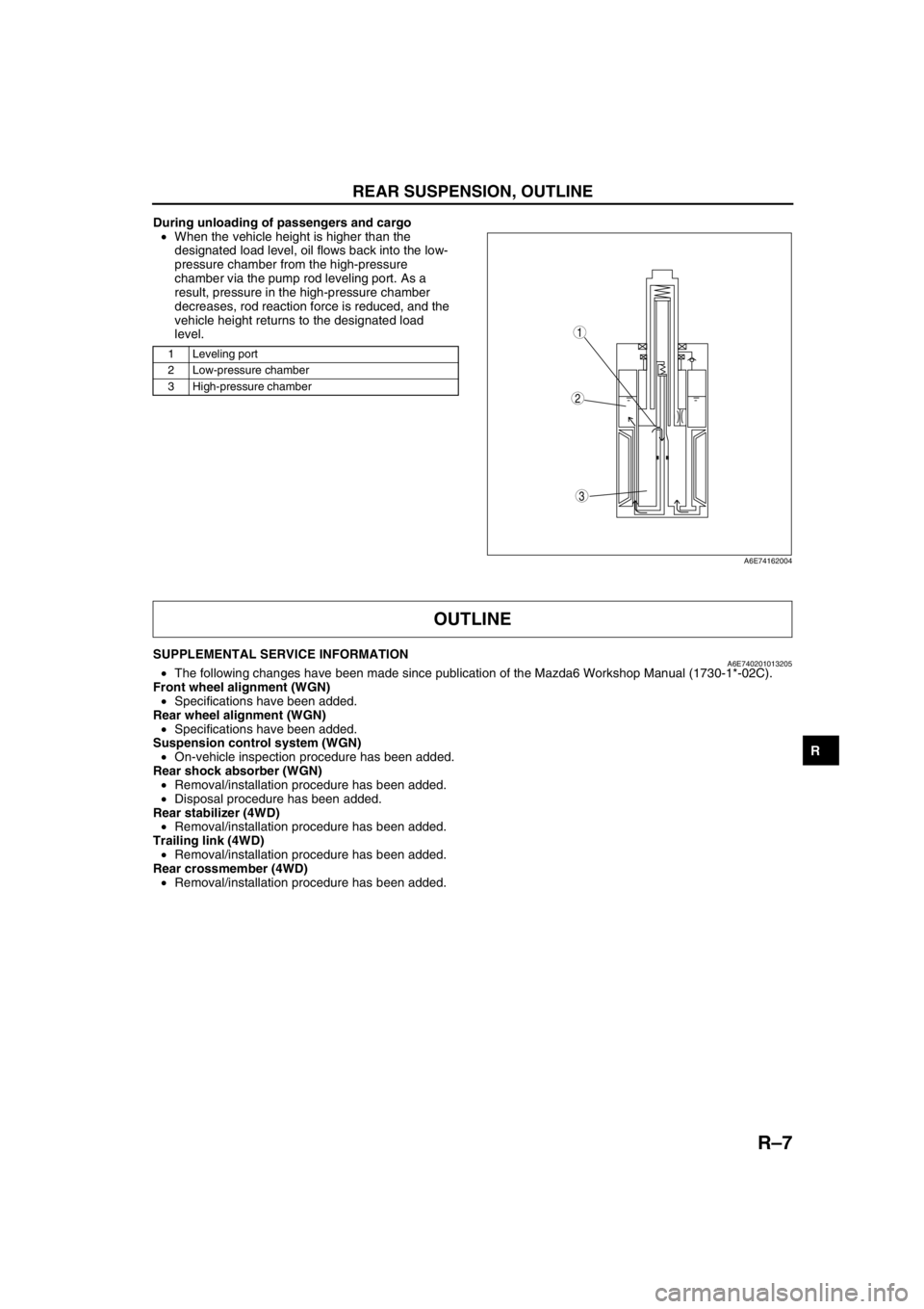
During unloading of passengers and cargo
•When the vehicle height is higher than the
designated load level, oil flows back into the low-
pressure chamber from the high-pressure
chamber via the pump rod leveling port. As a
result, pressure in the high-pressure chamber
decreases, rod reaction force is reduced, and the
vehicle height returns to the designated load
level.
.
End Of Sie
SUPPLEMENTAL SERVICE INFORMATIONA6E740201013205•The following changes have been made since publication of the Mazda6 Workshop Manual (1730-1*-02C).
Front wheel alignment (WGN)
•Specifications have been added.
Rear wheel alignment (WGN)
•Specifications have been added.
Suspension control system (WGN)
•On-vehicle inspection procedure has been added.
Rear shock absorber (WGN)
•Removal/installation procedure has been added.
•Disposal procedure has been added.
Rear stabilizer (4WD)
•Removal/installation procedure has been added.
Trailing link (4WD)
•Removal/installation procedure has been added.
Rear crossmember (4WD)
•Removal/installation procedure has been added.
End Of Sie
1 Leveling port
2 Low-pressure chamber
3 High-pressure chamber
3
1
2
A6E74162004
OUTLINE
Page 770 of 909
R–8
WHEEL ALIGNMENT
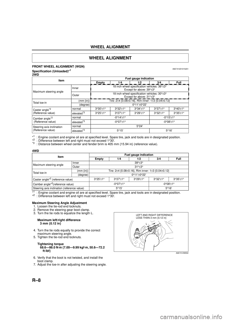
FRONT WHEEL ALIGNMENT (WGN)A6E741201015201Specification (Unloaded)*1
2WD
*
1: Engine coolant and engine oil are at specified level. Spare tire, jack and tools are in designated position.
*2: Difference between left and right must not exceed 1 °30'.*3: Distance between wheel center and fender brim is 405 mm {15.94 in} (reference value).
4WD
*
1: Engine coolant and engine oil are at specified level. Spare tire, jack and tools are in designated position.
*2: Difference between left and right must not exceed 1 °30'.
Maximum Steering Angle Adjustment 1. Loosen the tie-rod end locknuts.
2. Remove the steering gear boot clamp.
3. Turn the tie rods to equalize the length L.
Maximum left/right difference3 mm {0.12 in}
4. Turn the tie rods equally to provide the correct maximum steering angle.
5. Tighten the tie-rod end locknuts.
Tightening torque68.6—98.0 N·m {7.00—9.99 kgf·m, 50.6—72.2 ft·lbf}
6. Verify that the boot is not twisted, and install the boot clamp.
7. Adjust the toe-in after adjusting the steering angle.
WHEEL ALIGNMENT
Item Fuel gauge indication
Empty 1/4 1/2 3/4 Full
Maximum steering angle Inner
18 inch wheel specification vehicles: 36
°±3°
Except for above: 39 °±3°
Outer 18 inch wheel specification vehicles: 30
°±3°
Except for above: 31 °±3°
Total toe-in (mm {in}) Tire: 2
±4 {0.08 ±0.16}, Rim inner: 1 ±3 {0.04 ±0.12}
(degree) 0 °11 ′±0°22 ′
Caster angle
*2
(Reference value) normal 3
°30' ±1 ° 3°32' ±1 ° 3°34' ±1° 3°37' ±1° 3°40' ±1 °
elevated*33 °25' ±1 ° 3°27' ±1 ° 3°29' ±1° 3°32' ±1° 3°35' ±1 °
Camber angle
*2
(Reference value) normal -0
°14' ±1 ° -0°15' ±1°
elevated*3-0 °07' ±1 ° -0°08' ±1°
Steering axis inclination
(Reference value) normal 5
°24'
elevated
*35 °15' 5 °16'
Item Fuel gauge indication
Empty 1/4 1/2 3/4 Full
Maximum steering angle Inner 39
°±3°
Outer 31 °±3°
Total toe-in (mm {in}) Tire: 2
±4 {0.08 ±0.16}, Rim inner: 1 ±3 {0.04 ±0.12}
(degree) 0 °11 ′±0°22 ′
Caster angle*
2 (reference value) 3
°25' ±1 ° 3°27' ±1 ° 3°29' ±1 ° 3°32' ±1 ° 3°35' ±1 °
Camber angle*
2(reference value) -0
°07' ±1 ° -0°08' ±1°
Steering axis inclination (reference value) 5 °15' 5 °16'
LEFT AND RIGHT DIFFERENCE
L
LESS THAN 3 mm {0.12 in}
A6E7412W002
Page 771 of 909
WHEEL ALIGNMENT
R–9
R
Total Toe-in Adjustment
1. Center the steering wheel and confirm that the vehicle wheels/tires are pointing straight.
2. Loosen the left and right tie-rod end locknuts and turn the tie-rods equally. Both tie rods are right threaded, so
turning the right tie-rod toward the front of the vehicle and the left toward the rear increases toe-in.
Note
•Turning both tie-rods one complete turn changes toe-in by about 6 mm {0.24 in} (0°36').
3. Tighten the tie-rod end locknuts to the specified torque.
Tightening torque
68.6—98.0 N·m {7.00—9.99 kgf·m, 50.6—72.2 ft·lbf}
4. Verify that the boot is not twisted, and install the boot clamp.
End Of Sie
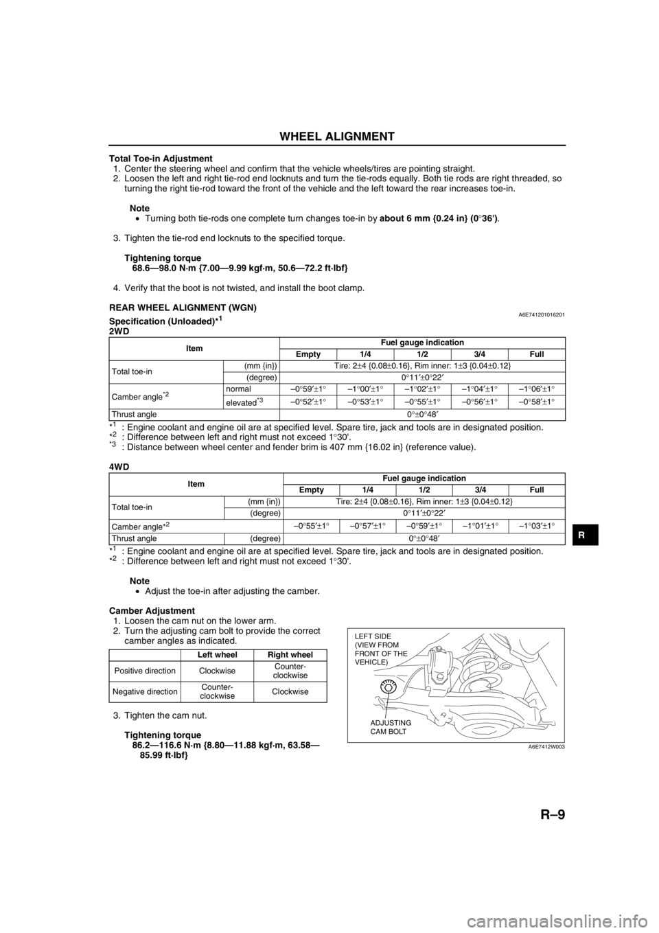
REAR WHEEL ALIGNMENT (WGN)A6E741201016201Specification (Unloaded)*1
2WD
*
1: Engine coolant and engine oil are at specified level. Spare tire, jack and tools are in designated position.
*2: Difference between left and right must not exceed 1°30'.*3: Distance between wheel center and fender brim is 407 mm {16.02 in} (reference value).
4WD
*
1: Engine coolant and engine oil are at specified level. Spare tire, jack and tools are in designated position.
*2: Difference between left and right must not exceed 1°30'.
Note
•Adjust the toe-in after adjusting the camber.
Camber Adjustment
1. Loosen the cam nut on the lower arm.
2. Turn the adjusting cam bolt to provide the correct
camber angles as indicated.
3. Tighten the cam nut.
Tightening torque
86.2—116.6 N·m {8.80—11.88 kgf·m, 63.58—
85.99 ft·lbf}
ItemFuel gauge indication
Empty 1/4 1/2 3/4 Full
Total toe-in(mm {in}) Tire: 2±4 {0.08±0.16}, Rim inner: 1±3 {0.04±0.12}
(degree) 0°11′±0°22′
Camber angle
*2 normal–0°59′±1°–1°00′±1°–1°02′±1°–1°04′±1°–1°06′±1°
elevated
*3–0°52′±1°–0°53′±1°–0°55′±1°–0°56′±1°–0°58′±1°
Thrust angle 0°±0°48′
ItemFuel gauge indication
Empty 1/4 1/2 3/4 Full
Total toe-in(mm {in}) Tire: 2±4 {0.08±0.16}, Rim inner: 1±3 {0.04±0.12}
(degree) 0°11′±0°22′
Camber angle*
2 –0°55′±1°–0°57′±1°–0°59′±1°–1°01′±1°–1°03′±1°
Thrust angle (degree) 0°±0°48′
Left wheel Right wheel
Positive direction ClockwiseCounter-
clockwise
Negative directionCounter-
clockwiseClockwise
LEFT SIDE
(VIEW FROM
FRONT OF THE
VEHICLE)
ADJUSTING
CAM BOLT
A6E7412W003
Page 772 of 909

R–10
WHEEL ALIGNMENT
Total Toe-in Adjustment
1. Loosen the locknut of the lateral link.
2. Adjust the toe-in turning the adjusting link.
Specification
Total Toe-in: 2±4 mm {0.08±0.16 in}
Note
•Toe change amount: 0°43′ / one rotation
3. Tighten the locknut.
Tightening torque
68.6—98.1 N·m {7.0—10.0 kgf·m, 50.6—72.3
ft·lbf}
End Of Sie
A6E7412W004
A6E7412W005
A6E7412W004