wheel bolts MAZDA 6 2002 Workshop Manual Suplement
[x] Cancel search | Manufacturer: MAZDA, Model Year: 2002, Model line: 6, Model: MAZDA 6 2002Pages: 909, PDF Size: 17.16 MB
Page 152 of 909

F1–64
TROUBLESHOOTING
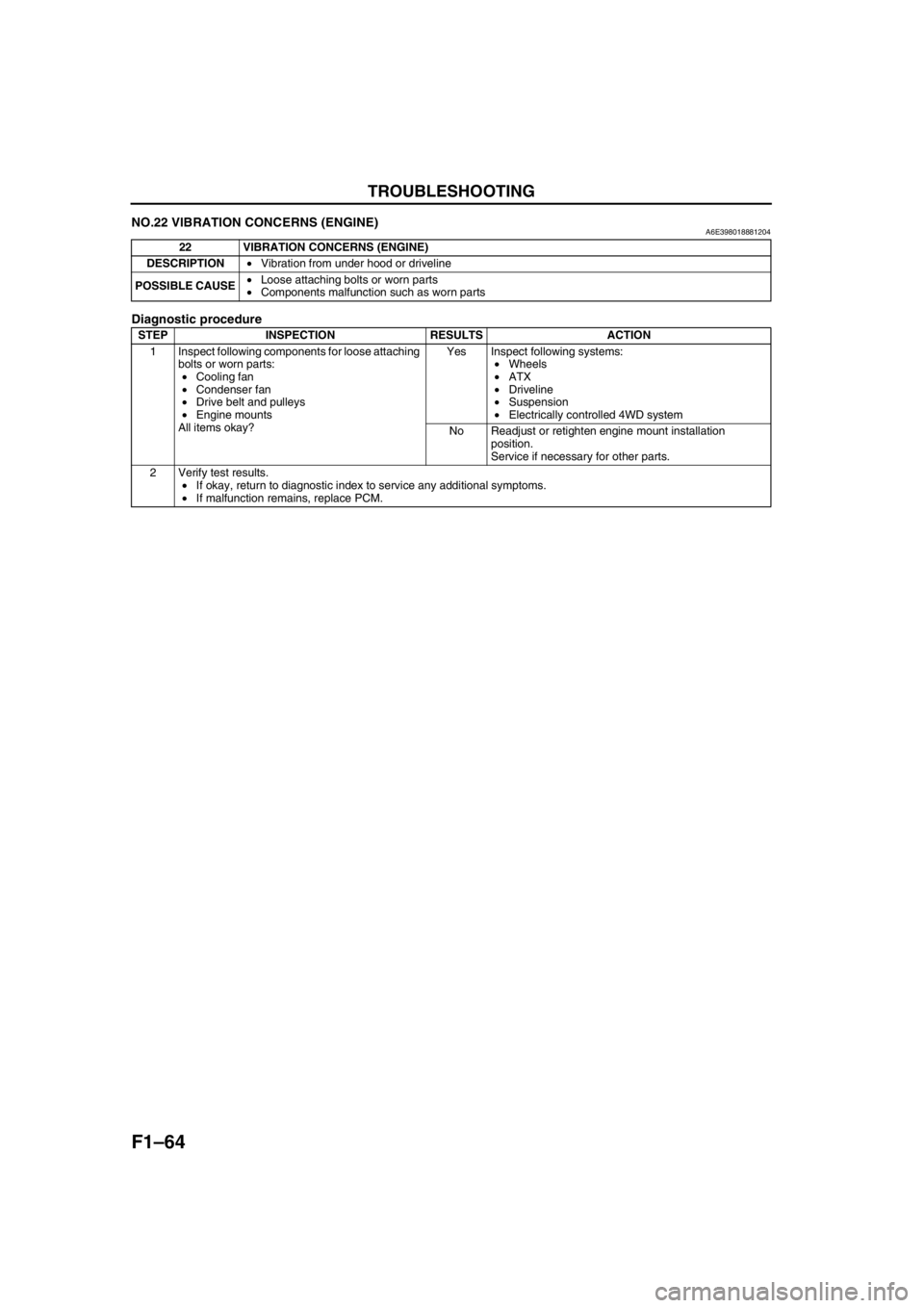
NO.22 VIBRATION CONCERNS (ENGINE)A6E398018881204
Diagnostic procedure
End Of Sie
22 VIBRATION CONCERNS (ENGINE)
DESCRIPTION•Vibration from under hood or driveline
POSSIBLE CAUSE•Loose attaching bolts or worn parts
•Components malfunction such as worn parts
STEP INSPECTION RESULTS ACTION
1 Inspect following components for loose attaching
bolts or worn parts:
•Cooling fan
•Condenser fan
•Drive belt and pulleys
•Engine mounts
All items okay?Yes Inspect following systems:
•Wheels
•ATX
•Driveline
•Suspension
•Electrically controlled 4WD system
No Readjust or retighten engine mount installation
position.
Service if necessary for other parts.
2 Verify test results.
•If okay, return to diagnostic index to service any additional symptoms.
•If malfunction remains, replace PCM.
Page 371 of 909

TROUBLESHOOTING
F2–219
F2
End Of Sie
14 Inspect if turbocharger compressor wheel
locknut is loose or has fallen down inside
turbocharger.
Is there any problem?Yes Replace turbocharger.
No Go to next step.
15 Turn turbocharger compressor wheel by hand.
Does wheel turn easily and smoothly?Yes Go to next step.
No Replace turbocharger.
16 Inspect if turbocharger turbine wheel is
damaged, cracked or interfering with housing on
vehicle.
Note
•Inspect all fins on each turbine wheel.
Is there any problem?Yes Replace turbocharger.
No Go to next step.
17 Is any engine oil found inside turbocharger
turbine housing?YesExcessive amount of oil is found:
Replace turbocharger.
Small amount of oil is found:
Wipe oil off of vehicle, then go to next step.
No Go to next step.
18 Is any engine oil found inside turbocharger
compressor housing?Yes Wipe oil off of vehicle, then go to next step.
No Go to next step.
19 Is any exhaust gas leakage found around
location where turbocharger is attached to
exhaust manifold?Yes Remove turbocharger.
Inspect for cracks on center housing inlet surface.
If cracks are found, replace turbocharger.
No Go to next step.
20 Are any center housing and turbine housing
attaching bolts loose?Yes Retighten loose bolts.
If a bolt is found to be missing, attach appropriate new
bolts.
No Turbocharger is okay.
Install all parts removed in Step 13.
Go to next step.
21 Inspect suction control valve.
(See F2–54 SUCTION CONTROL VALVE
INSPECTION)
Is suction control valve okay?Yes Go to next step.
No Repair supply pump.
(See F2–54 SUPPLY PUMP INSPECTION)
22 Inspect fuel injector and fuel injector gasket.
(See F2–56 FUEL INJECTOR INSPECTION)
Is fuel injector okay?Yes Inspect for following:
•Metal flow
•Bent connecting rod
•Damaged valve seat
•Incorrect valve clearance
No Repair or replace as necessary.
23 Verify test results.
•If okay, return to diagnostic index to service any additional symptoms.
•If malfunction remains, replace PCM. (See F2–64 PCM REMOVAL/INSTALLATION) STEP INSPECTION RESULTS ACTION
Page 372 of 909

F2–220
TROUBLESHOOTING
NO.22 VIBRATION CONCERNS (ENGINE)A6E408018881224
Diagnostic Procedure
22 VIBRATION CONCERNS (ENGINE)
DESCRIPTION•Vibration from under hood or driveline.
POSSIBLE
CAUSE•Loose attaching bolts or worn parts
•Cooling fan No.1 or cooling fan No.2 seat are improper
•Engine or transaxle mounts are improperly installed
•Components malfunction such as worn parts
•Erratic signal from CMP sensor
•ECT sensor or related circuit malfunction
•Accelerator position sensor or related circuit malfunction
•MAF/IAT sensor or related circuit malfunction
•Idle switch or related circuit malfunction
•Incorrect adjustment of accelerator position sensor and/or idle switch
•Fuel injector malfunction
•Vacuum leakage
•Improper tension or damaged drive belts
•Improper balance of wheels or tires
•Driveline malfunction
•Suspension malfunction
Warning
The following troubleshooting flow chart contains the fuel system diagnosis and repair
procedures. Read the following warnings before performing the fuel system services:
•Fuel vapor is hazardous. It can easily ignite, causing serious injury and damage. Always keep
sparks and flames away from fuel.
•Fuel line spills and leakage are dangerous. Fuel can ignite and cause serious injury or death
and damage. Fuel can also irritate skin and eyes. To prevent this, always complete “BEFORE
REPAIR PROCEDURE” and “AFTER REPAIR PROCEDURE” described in this manual.
STEP INSPECTION RESULTS ACTION
1 Inspect following components for loose attaching
bolts or worn parts:
•Cooling fan No.1
•Cooling fan No.2
•Cooling fan No.1 and cooling fan No.2 seat
•Drive belt and pulley
•Engine mounts
•Exhaust system
Are all items okay?Yes Go to next step.
No Readjust or retighten engine mount installation
position.
Service as necessary for other parts.
2 Inspect vacuum leakage.
Are vacuum hoses okay?Yes Go to next step.
No Service as necessary.
Repeat Step 2.
Page 400 of 909

H–6
CLUTCH UNIT
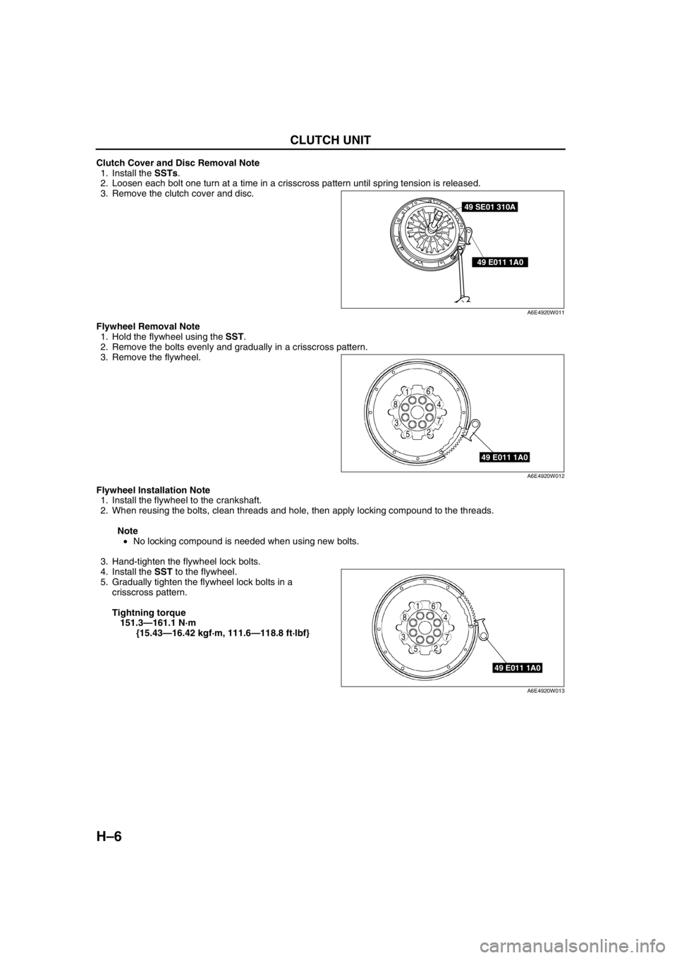
Clutch Cover and Disc Removal Note
1. Install the SSTs.
2. Loosen each bolt one turn at a time in a crisscross pattern until spring tension is released.
3. Remove the clutch cover and disc.
Flywheel Removal Note
1. Hold the flywheel using the SST.
2. Remove the bolts evenly and gradually in a crisscross pattern.
3. Remove the flywheel.
Flywheel Installation Note
1. Install the flywheel to the crankshaft.
2. When reusing the bolts, clean threads and hole, then apply locking compound to the threads.
Note
•No locking compound is needed when using new bolts.
3. Hand-tighten the flywheel lock bolts.
4. Install the SST to the flywheel.
5. Gradually tighten the flywheel lock bolts in a
crisscross pattern.
Tightning torque
151.3—161.1 N·m
{15.43—16.42 kgf·m, 111.6—118.8 ft·lbf}
49 SE01 310A
49 E011 1A0
A6E4920W011
49 E011 1A0
5
4
3
61
2
8
7
A6E4920W012
49 E011 1A0
5
4
3
61
2
8
7
A6E4920W013
Page 409 of 909

MANUAL TRANSAXLE
J2–7
J2
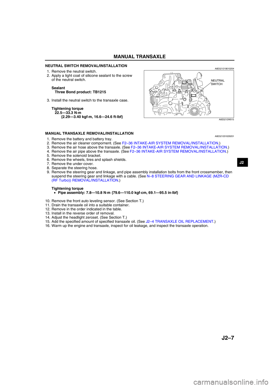
NEUTRAL SWITCH REMOVAL/INSTALLATIONA6E5212190102041. Remove the neutral switch.
2. Apply a light coat of silicone sealant to the screw
of the neutral switch.
Sealant
Three Bond product: TB1215
3. Install the neutral switch to the transaxle case.
Tightening torque
22.5—33.3 N·m
{2.29—3.40 kgf·m, 16.6—24.6 ft·lbf}
End Of Sie
MANUAL TRANSAXLE REMOVAL/INSTALLATIONA6E5212010292011. Remove the battery and battery tray.
2. Remove the air cleaner compornent. (See F2–36 INTAKE-AIR SYSTEM REMOVAL/INSTALLATION.)
3. Remove the air hose above the transaxle. (See F2–36 INTAKE-AIR SYSTEM REMOVAL/INSTALLATION.)
4. Remove the air pipe above the transaxle. (See F2–36 INTAKE-AIR SYSTEM REMOVAL/INSTALLATION.)
5. Remove the solenoid bracket.
6. Remove the wheels, tires and splash shields.
7. Remove the under cover.
8. Separate the steering hose.
9. Remove the steering gear and linkage, and pipe assembly installation bolts from the front crossmember, then
suspend the steering gear and linkage with a cable. (See N–8 STEERING GEAR AND LINKAGE (MZR-CD
(RF Turbo)) REMOVAL/INSTALLATION.)
Tightening torque
•Pipe assembly: 7.8—10.8 N·m {79.6—110.0 kgf·cm, 69.1—95.5 in·lbf}
10. Remove the front auto leveling sensor. (See Section T.)
11. Drain the transaxle oil into a suitable container.
12. Remove in the order indicated in the table.
13. Install in the reverse order of removal.
14. Adjust the headlight zeroset. (See Section T.)
15. Add the specified amount of specified transaxle oil. (See J2–4 TRANSAXLE OIL REPLACEMENT.)
16. Warm up the engine and transaxle, inspect for oil leakage, and inspect the transaxle operation.
NEUTRAL
SWITCH
A6E5212W015
Page 654 of 909

M–24
REAR AXLE
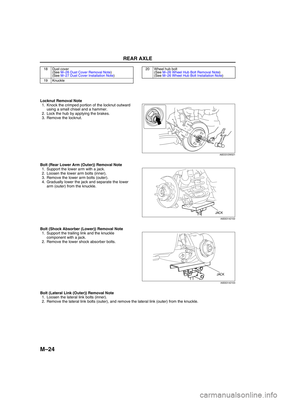
Locknut Removal Note
1. Knock the crimped portion of the locknut outward
using a small chisel and a hammer.
2. Lock the hub by applying the brakes.
3. Remove the locknut.
Bolt (Rear Lower Arm (Outer)) Removal Note
1. Support the lower arm with a jack.
2. Loosen the lower arm bolts (inner).
3. Remove the lower arm bolts (outer).
4. Gradually lower the jack and separate the lower
arm (outer) from the knuckle.
Bolt (Shock Absorber (Lower)) Removal Note
1. Support the trailing link and the knuckle
component with a jack.
2. Remove the lower shock absorber bolts.
Bolt (Lateral Link (Outer)) Removal Note
1. Loosen the lateral link bolts (inner).
2. Remove the lateral link bolts (outer), and remove the lateral link (outer) from the knuckle.
18 Dust cover
(See M–26 Dust Cover Removal Note)
(See M–27 Dust Cover Installation Note)
19 Knuckle20 Wheel hub bolt
(See M–26 Wheel Hub Bolt Removal Note)
(See M–26 Wheel Hub Bolt Installation Note)
A6E0312W021
JACK
A6E63142102
JACK
A6E63142103
Page 655 of 909

REAR AXLE
M–25
M
Bolt (Trailing Link (Front)) Removal Note
Warning
•Be sure that the trailing link and the knuckle component are supported securely with a jack.
Otherwise, the trailing link and/or the knuckle component may fall, causing death or injury, or
vehicle damage.
1. Verify that the trailing link and the knuckle
component are supported securely with a jack,
and remove the bolts at the trailing link front.
Wheel Hub Removal Note
1. Remove the wheel hub from the knuckle using
the SSTs.
2. If the bearing inner race remains on the wheel
hub, grind a section of the bearing inner race until
approx. 0.5 mm {0.02 in} remains. Then remove
it using a chisel.
Wheel Bearing Removal Note
1. Remove the wheel bearing from the knuckle
using the SSTs.
JACK
A6E63142103
49 G033 105
49 F026 103
49 G033 102
A6J63142104
A6E6312W002
49 F027 005
49 F026 103
49 G030 797
A6J63142105
Page 656 of 909

M–26
REAR AXLE
Dust Cover Removal Note
Note
•The dust cover does not need to be removed unless it is being replaced.
1. Mark the dust cover and knuckle for proper
installation.
2. Remove the dust cover from the knuckle using a
chisel.
Wheel Hub Bolt Removal Note
Note
•The wheel hub bolts do not need to be removed unless they are being replaced.
1. Remove the wheel hub bolts from the wheel hub
using a press.
Wheel Hub Bolt Installation Note
1. Install the new wheel hub bolts to the wheel hub
using a press.
MARK
A6E63142104
A6E6312W003
A6E6312W004
Page 778 of 909

R–16
REAR SUSPENSION
Bolt (Trailing Link Front Side) Removal Note
1. Support the trailing link with a jack.
Caution
•Removing the trailing link is dangerous.
The trailing link could fall and cause
serious injury or death. Verify that the
jack securely supports the trailing link.
2. Remove the bolts (trailing link front side).
Bolt (Lateral Link Outer Side) Removal Note
1. Loosen the bolt (lateral link inner side).
2. Remove the bolt (lateral link outer side).
Bolt (Lateral Link Outer Side) Installation Note
1. Tighten the bolt (lateral link outer side).
2. Tighten the bolt (lateral link inner side).
Tightening torque
86.2—116.6 N·m {8.80—11.88 kgf·m, 63.58—85.99 ft·lbf}
Bolt (Trailing Link Front Side) Installation Note
1. Support the trailing link with a jack.
2. Tighten the bolts (trailing link front side).
End Of SieREAR CROSSMEMBER REMOVAL/INSTALLATION (4WD)A6E741628400201
Caution
•Performing the following procedures without first removing the ABS wheel-speed sensor may
possibly cause an open circuit in the harness if it is pulled by mistake. Before performing the
following procedures, remove the ABS wheel-speed sensor (axle side) and fix it to an appropriate
place where the sensor will not be pulled by mistake while servicing the vehicle.
1. Remove the rear auto leveling sensor and harness.
(See T–20 REAR AUTO LEVELING SENSOR REMOVAL/INSTALLATION.)
2. Remove the middle pipe.
(See F1–30 EXHAUST SYSTEM REMOVAL/INSTALLATION.)
3. Remove in the order indicated in the table.
4. Install in the reverse order of removal.
5. Adjust the headlight zeroset.
6. Inspect the rear wheel alignment.
(See R–9 REAR WHEEL ALIGNMENT (WGN).)
JACK
A6E74162010
JACK
A6E74162010