alternator MAZDA 626 1987 User Guide
[x] Cancel search | Manufacturer: MAZDA, Model Year: 1987, Model line: 626, Model: MAZDA 626 1987Pages: 1865, PDF Size: 94.35 MB
Page 210 of 1865

INSTALLATION 1B
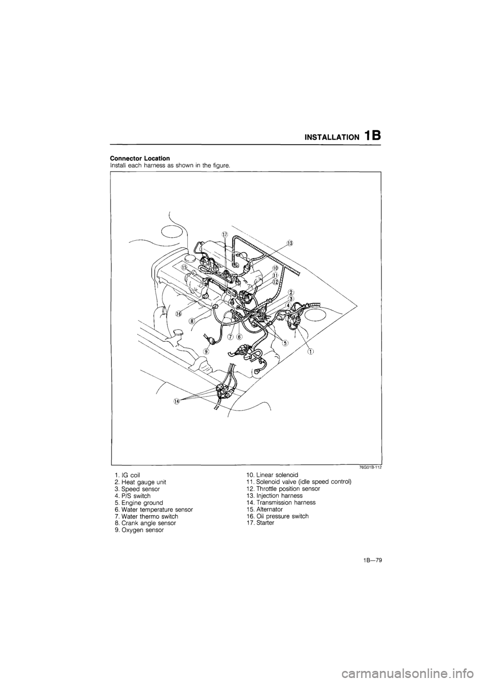
Connector Location
Install each harness as shown in the figure.
76G01B-112
1. IG coil 10. Linear solenoid
2. Heat gauge unit 11. Solenoid valve (idle speed control)
3. Speed sensor 12. Throttle position sensor
4. P/S switch 13. Injection harness
5. Engine ground 14. Transmission harness
6. Water temperature sensor 15. Alternator
7. Water thermo switch 16. Oil pressure switch
8. Crank angle sensor 17. Starter
9. Oxygen sensor
1B-79
Page 216 of 1865

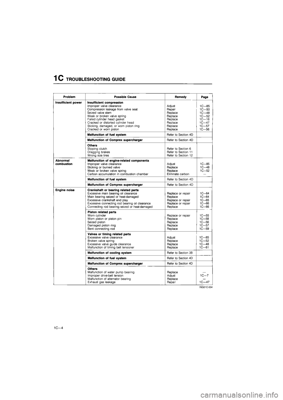
1 C TROUBLESHOOTING GUIDE
Problem Possible Cause Remedy Page
Insufficient power Insufficient compression Improper valve clearance Compression leakage from valve seat Seized valve stem Weak or broken valve spring Failed cylinder head gasket Cracked or distorted cylinder head Sticking, damaged, or worn piston ring Cracked or worn piston
Adjust
Repair
Replace Replace Replace Replace Replace Replace
1C-85 1C-50 1C-48 1C-52 1C—16 1C-47 1C-57 1C-56
Malfunction of fuel system Refer to Section 4D
Malfunction of Comprex supercharger Refer to Section 4D
Others Slipping clutch Dragging brakes Wrong size tires
Refer to Section 6 Refer to Section 11 Refer to Section 12
Abnormal
combustion
Malfunction of engine-related components
Improper valve clearance
Sticking or burned valve
Weak or broken valve spring
Carbon accumulation in combustion chamber
Adjust
Replace
Replace Eliminate carbon
1C-85
1C-48
1C-52
Malfunction of fuel system Refer to Section 4D
Malfunction of Comprex supercharger Refer to Section 4D
Engine noise Crankshaft or bearing related parts Excessive main bearing oil clearance Main bearing seized or heat-damaged Excessive crankshaft end play Excessive connecting rod bearing oil clearance Connecting rod bearing seized or heat-damaged
Replace or repair Replace
Replace or repair Replace or repair Replace
1C-64 1C-64 1C-65 1C-66 1C-66
Piston related parts Worn cylinder Worn piston or piston pin Seized piston Damaged piston ring Bent connecting rod
Replace or repair Replace
Replace Replace Replace
1C-55 1C-58 1C-56 1C-57 1C-59
Valves or timing related parts Excessive valve clearance Broken valve spring Excessive valve guide clearance Malfunction of timing belt tensioner
Adjust Replace Replace Replace
1C-85 1C-52 1C-48 1C-61
Malfunction of cooling system Refer to Section 3B
Malfunction of fuel system Refer to Section 4D
Malfunction of Comprex supercharger Refer to Section 4D
Others Malfunction of water pump bearing Improper drive-belt tension Malfunction of alternator bearing Exhaust gas leakage
Replace Adjust Replace Repair
1C-7
1C—47
76G01C-004
1C—4
Page 219 of 1865

TUNE-UP PROCEDURE 1C
P/S oil pump Checking point
B
Vacuum/^ i V pumpf o ) y ®
v Rear \ camshaft
J
pulley
A-—mP
P/S oil pump \ L^
76G01C-009
Drive Belt
1. Check the drive belt for wear, cracks, or fraying.
Replace if necessary.
2. Check the drive belt deflection by applying moder-
ate pressure (98 N, 10 kg, 22 lb) midway between
the pulleys.
Alternator
Deflection mm (in)
New 8.0-10.0 (0.31-0.39)
Used 9.0—11.0 (0.35—0.43)
If necessary, loosen the idler lock nut and adjust
the belt deflection by turning the adjust bolt.
Tightening torque:
37—52 N-m (3.8—5.3 m-kg, 27—38 ft-lb)
Vacuum pump and P/S oil pump
Deflection mm (in)
Vacuum
pump
New 7.5-8.5 (0.30-0.33) Vacuum
pump Used 8.5-9.5 (0 33-0.37)
P/S oil pump
New 6.5-7.5 (0.26-0 30) P/S oil pump Used 7.0-8.0 (0.28—0.31)
If necessary, adjust the belt deflection as follows.
(1) Loosen the vacuum pump bolts ©and (§).
(2) Lever the vacuum pump outward and apply
tension to the belt.
(3)Tighten the adjust bolt
Tightening torque:
19—26
N
m (1.9—2.6 m-kg, 14—19 ft-lb)
(4)Tighten the mounting bolt
Tightening torque:
37—52
N
m (3.8—5.3 m-kg, 27—38 ft-lb)
A/C compressor
Deflection mm (in)
New 8.5—9.5 (0.33—0.37)
Used 9.5-10.5 (0.37-0.41)
If necessary, loosen the idler lock nut and adjust
the belt deflection by turning the adjust bolt.
Tightening torque:
37—52 Nm (3.8—5.3 m-kg, 27—38 ft-lb)
1C-7
Page 223 of 1865

ON-VEHICLE MAINTENANCE (TIMING BELT) 1 C
ON-VEHICLE MAINTENANCE
TIMING BELT
Removal
1. Disconnect the nagative battery cable.
2. Remove in the sequence shown in the figure referring to the removal note for specially marked parts.
76G01C-019
1. Engine side cover
2. A/C and alternator drive belt
3. Crankshaft pulley
4. Left and right timing belt cover
5. Alternator idle pulley
6. Idler pulley
7. No.3 engine mount
8. Timing belt
9. Timing belt tensioner and spring
Note
Loosen the No.3 engine mount nuts and lower the engine to remove the crankshaft pulley.
1C-11
Page 247 of 1865

DISASSEMBLY (AUXILIARY PARTS) 1 C
1. A/C compressor bracket 9. Alternator and drive belt
2. Vacuum pump and drive belt 10. Oil filter
3. Air funnel assembly 11. Oil filter cover
4. Comprex supercharger insulator 12. Oil cooler assembly
5. Comprex supercharger and drive belt 13. Exhaust pipe bracket
6. Exhaust manifold insulator 14. Alternator bracket
7. Exhaust manifold 15. Blow-by chamber
8. Intake manifold
Blow-by chamber
76G01C-074
Disassembly Note
Engine hanger
1. Remove the CSD hose.
2. Loosen the vacuum pump oil pipe bolts.
76G01C-075
3. Install the engine on the SST.
76G01C-076
1C—35
Page 299 of 1865

AUXILIARY PARTS
Torque Specifications
ASSEMBLY (AUXILIARY PARTS) 1 C
RF-N
19—26 N m (1.9—2.6 m-kg, 14—19 ft-lb)
22—26 N
(2.2-2.7 16—20 ft-lb)
8—11 N m (80—110 cm-kg, '-g 69—95 in-lb)
0—110 cm-kg, 169—95 in-lb)
. 22—26 N m (2.2—2.7 m-kg, 16—20 ft-lb)
37—52 N m (3.8—5.3 m-kg, 27—38 ft-lb) I
8—11 N-m (80—110 cm-kg, 69—95 In-lb)
37—52 N-m (3,8—5.3 m-kg, 27-38 ft-lb)
86U01X-164
Alternator Bracket and Exhaust Pipe Bracket
Install the alternator bracket and exhaust pipe stay.
Tightening torque:
37—52
N
m (3.8—5.3 m-kg, 27—38 ft-lb)
p o
a^z iw rr
76G01C-212
1C—87
Page 300 of 1865

1 C ASSEMBLY (AUXILIARY PARTS)
76G01C-205
76G01C-206
76G01C-207
o e-
Oil Cooler Assembly
1. Clean the contact surfaces of the cylinder block
and oil filter assembly.
2. Install new O-rings, and apply a coat of engine oil.
3. Install the oil cooler assembly.
Tightening torque:
Bolt A: 8—11 N-m
(80—110 cm-kg, 69—95 in-lb)
Bolt B: 37—52 N-m
(3.8—5.3 m-kg, 27—38 ft-lb)
4. Connect the water hose.
Oil Filter
1. Install the oil filter cover.
Tightening torque:
8—11 N-m (80—110 cm-kg, 69—95 in-lb)
2. Apply a coat of engine oil to the filter rubber seal.
3. Install the oil filter until the rubber seal contacts the
oil cooler by hand. Then tighten it a 7/6 turn fur-
ther with a band type wrench.
Alternator
1. Install the alternator.
Tightening torque:
Bolt A: 19—26 N m
(1.9—2.6 m-kg, 14—19 ft-lb)
Bolt B: 37—52 N-m
(3.8—5.3 m-kg, 27—38 ft-lb)
2. Install the alternator drive belt, and adjust the belt
deflection. (Refer to page 1C—7)
76G01C-208
1C—88
expert22 ajia http://rutracker.org
Page 307 of 1865

INSTALLATION 1C
Heater Hose
Connect the heater hoses.
Note
Position the hose clamp in the original loca-
tion on the hose and squeeze the clamp lightly
with large pliers to ensure a good fit.
86U01X-221
Connector Location
Install each harness as shown in the figure.
1. Alternator
2. Boost air temperature sensor (RF-CX)
3. Heat gauge unit
4. Water thermo switch
5. Pick up coil
6. Glow cord
7. Front harness connector and ground
76G01C-222
8. Fuel cut valve
9. Oil pressure switch
10. Starter
11. Water temperature switch
12. Transaxle harness
13. Grounds
1C—95
Page 360 of 1865

WATER PUMP 3B
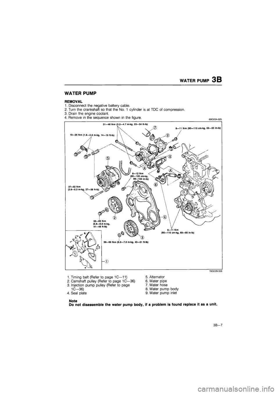
WATER PUMP
REMOVAL
1. Disconnect the negative battery cable.
2. Turn the crankshaft so that the No. 1 cylinder is at TDC of compression.
3. Drain the engine coolant.
4. Remove in the sequence shown in the figure. 69G03A-025
31—46 N m (3.2—4.7 m-kg, 23—34 ft-lb)
19—26 N-m (1.9—2.6 m-kg, 14—19 ft-lb)
(?) 8—11 N-m (80—110 cm-kg, 69—95 In-lb)
37—52 N-m (3.8—5.3 m-kg, 27—38 ft
55—65 N-m (5.6—6.6 m-kg, 41-48 ft-lb)
(80—110 cm-kg, 69—95 In-lb)
59—69 N-m (6.0—7.0 m-kg, 43—51 ft-lb)
76G03B-006
1. Timing belt (Refer to page 1C—11)
2. Camshaft pulley (Refer to page 1C—36)
3. Injection pump pulley (Refer to page
1C—36)
4. Seal plate
Note
Do not disassemble the water pump body, if a problem is found replace it as a unit.
5. Alternator
6. Water pipe
7. Water hose
8. Water pump body
9. Water pump inlet
3B-7
Page 361 of 1865

3B WATER PUMP
INSPECTION
Check the following. Replace the pump if necessary.
1. Cracks or damage
2. Abnormal noise, bearing sticking or loose
86U03X-014
INSTALLATION
Install in the reverse order of removal referring to the
installation note.
Installation Note
Water pump
1. Remove any gasket fragments, dirt or oil from the
contact surfaces.
2. Install the water pump and new gasket so that the
printed side of the gasket faces the water pump.
Tightening torque:
Bolt A: 31—46 N-m
(3.2—4.7 m-kg, 23—34 ft-lb)
Bolt B: 8—11 N-m
(80—110 cm-kg, 69—95 in-lb)
Water pipe
1. Apply a coat of vegetable oil to the O-ring.
2. Install the water pipe.
Tightening torque:
8—11 N-m (80—110 cm-kg, 69—95 in-lb)
3. Connect the water hose.
76G03B-008
Alternator
1. Install the alternator.
Tightening torque:
Bolt A: 19—26
N
m
(1.9—2.6 m-kg, 14—19 ft-lb)
Bolt B: 37—52 N-m
(3.8—5.3 m-kg, 27—38 ft-lb)
2. Install the alternator drive belt and Comprex su-
percharger drive belt, and adjust the belt deflec-
tion. (Refer to page 1C—7)
76G03B-009
3B—8