alternator MAZDA 626 1987 Workshop Manual
[x] Cancel search | Manufacturer: MAZDA, Model Year: 1987, Model line: 626, Model: MAZDA 626 1987Pages: 1865, PDF Size: 94.35 MB
Page 27 of 1865
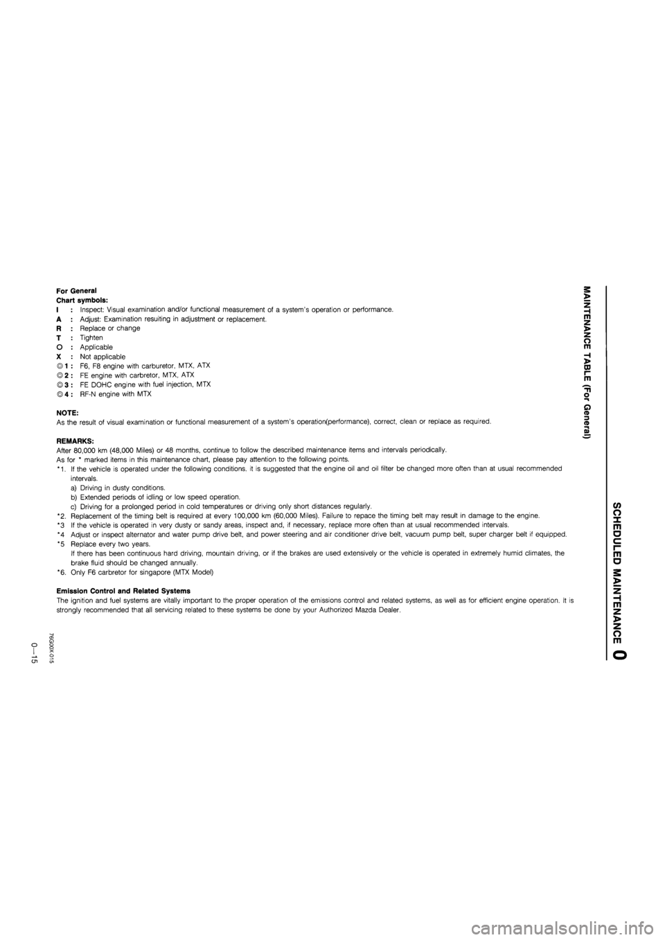
For General
Chart symbols:
I : Inspect: Visual examination and/or functional measurement of a system's operation or performance.
A : Adjust: Examination resuiting in adjustment or replacement.
R : Replace or change
T : Tighten
O : Applicable
X : Not applicable
© 1 : F6, F8 engine with carburetor, MTX, ATX
© 2 : FE engine with carbretor, MTX, ATX
©3 : FE DOHC engine with fuel injection, MTX
® 4 : RF-N engine with MTX
NOTE:
As the result of visual examination or functional measurement of a system's operation(performance), correct, clean or replace as required.
REMARKS:
After 80,000 km (48,000 Miles) or 48 months, continue to follow the described maintenance items and intervals periodically.
As for * marked items in this maintenance chart, please pay attention to the following points.
*1. If the vehicle is operated under the following conditions, it is suggested that the engine oil and oil filter be changed more often than at usual recommended
intervals.
a) Driving in dusty conditions.
b) Extended periods of idling or low speed operation.
c) Driving for a prolonged period in cold temperatures or driving only short distances regularly.
"2. Replacement of the timing belt is required at every 100,000 km (60,000 Miles). Failure to repace the timing belt may result in damage to the engine.
*3 If the vehicle is operated in very dusty or sandy areas, inspect and, if necessary, replace more often than at usual recommended intervals.
*4 Adjust or inspect alternator and water pump drive belt, and power steering and air conditioner drive belt, vacuum pump belt, super charger belt if equipped.
*5 Replace every two years.
If there has been continuous hard driving, mountain driving, or if the brakes are used extensively or the vehicle is operated in extremely humid climates, the
brake fluid should be changed annually.
*6. Only F6 carbretor for Singapore (MTX Model)
Emission Control and Related Systems
The ignition and fuel systems are vitally important to the proper operation of the emissions control and related systems, as well as for efficient engine operation. It i
strongly recommended that all servicing related to these systems be done by your Authorized Mazda Dealer.
o CJ1
Page 37 of 1865
TROUBLESHOOTING GUIDE 1 A
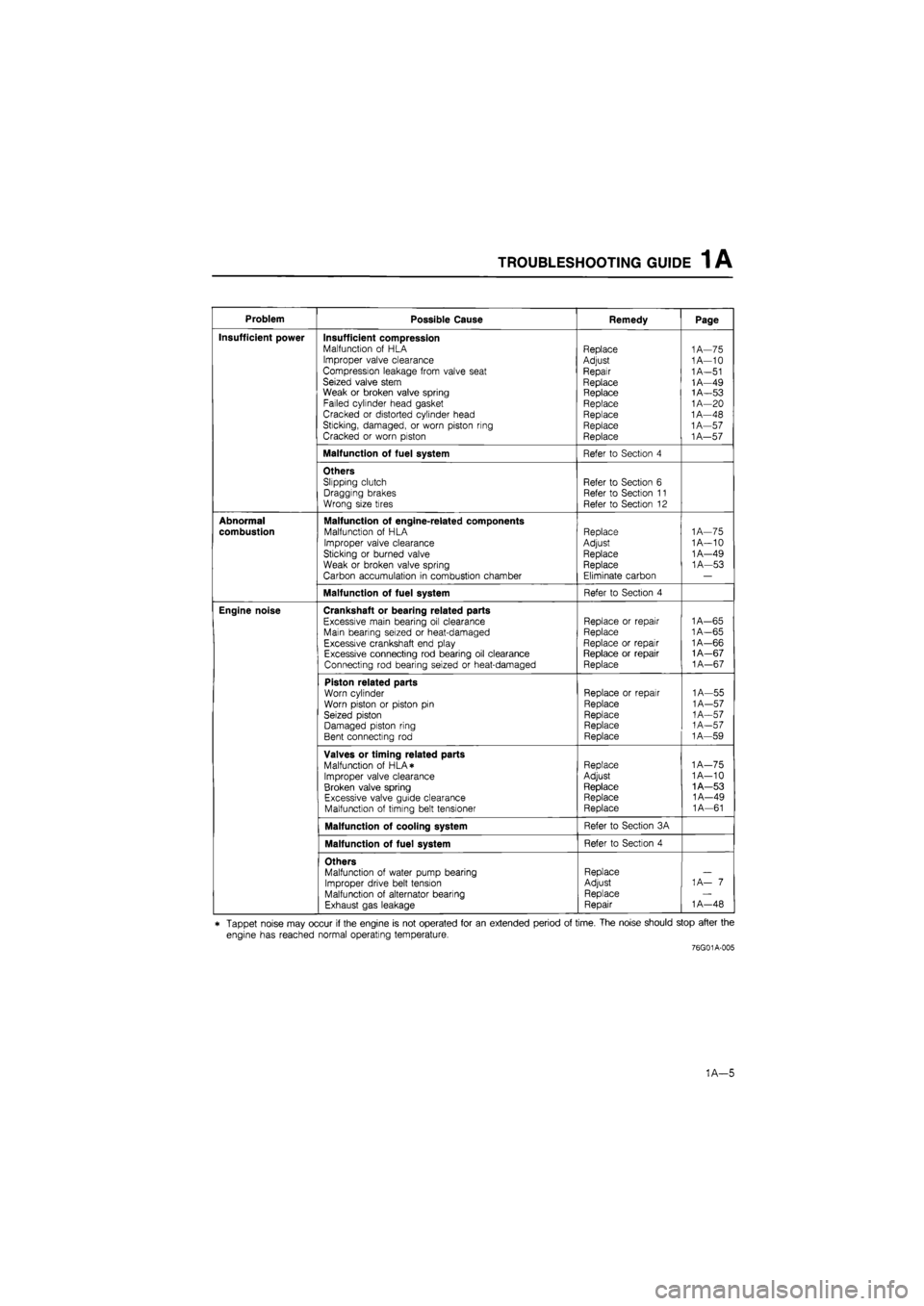
Problem Possible Cause Remedy Page
Insufficient power Insufficient compression Malfunction of HLA Improper valve clearance Compression leakage from valve seat Seized valve stem Weak or broken valve spring Failed cylinder head gasket Cracked or distorted cylinder head Sticking, damaged, or worn piston ring Cracked or worn piston
Replace
Adjust
Repair
Replace Replace Replace Replace Replace Replace
1A—75 1A—10
1
A—51 1A—49 1A—53
1
A—20 1A—48 1A—57
1
A—57
Malfunction of fuel system Refer to Section 4
Others Slipping clutch Dragging brakes Wrong size tires
Refer to Section 6 Refer to Section 11 Refer to Section 12
Abnormal
combustion
Malfunction of engine-related components Malfunction of HLA
Improper valve clearance Sticking or burned valve
Weak or broken valve spring Carbon accumulation in combustion chamber
Replace Adjust Replace Replace
Eliminate carbon
1
A—75 1A—10 1A—49 1A—53
Malfunction of fuel system Refer to Section 4
Engine noise Crankshaft or bearing related parts
Excessive main bearing oil clearance Main bearing seized or heat-damaged Excessive crankshaft end play Excessive connecting rod bearing oil clearance Connecting rod bearing seized or heat-damaged
Replace or repair Replace
Replace or repair Replace or repair Replace
1A—65
1
A—65 1A—66 1A—67
1
A—67
Piston related parts Worn cylinder Worn piston or piston pin Seized piston Damaged piston ring Bent connecting rod
Replace or repair
Replace
Replace Replace Replace
1A—55
1
A—57
1
A—57
1
A—57 1A—59
Valves or timing related parts Malfunction of HLA* Improper valve clearance Broken valve spring Excessive valve guide clearance Malfunction of timing belt tensioner
Replace Adjust
Replace Replace Replace
1A—75 1A—10 1A—53 1A—49 1A—61
Malfunction of cooling system Refer to Section 3A
Malfunction of fuel system Refer to Section 4
Others Malfunction of water pump bearing Improper drive belt tension Malfunction of alternator bearing Exhaust gas leakage
Replace Adjust Replace Repair
1 A— 7
1
A—48
* Tappet noise may occur if the engine is not operated for an extended period of time. The noise should stop after the
engine has reached normal operating temperature.
76G01A-005
1A—5
Page 39 of 1865
1A TUNE-UP PROCEDURE
Coolant Level (Cold engine)
1. Check that the coolant level is near the radiator inlet
port.
2. Check that the level in the coolant reservoir is be-
tween the FULL and LOW marks.
Add coolant if necessary.
Warning
a) Never remove the radiator cap while the en-
gine is hot.
b) Wrap a thick cloth around the cap and care-
fully remove it.
86U01X-008
When set
When measured
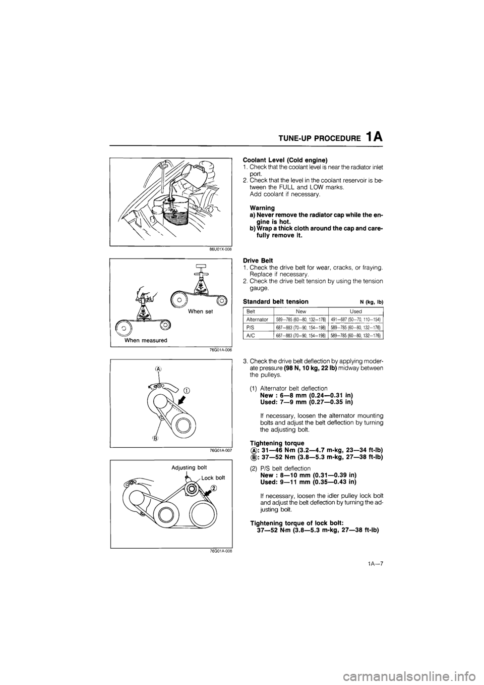
Drive Belt
1. Check the drive belt for wear, cracks, or fraying.
Replace if necessary.
2. Check the drive belt tension by using the tension
gauge.
Standard belt tension N (kg, lb)
Belt New Used
Alternator 589-785 (60-80, 132-176) 491-687 (50-70, 110-154)
P/S 687-883 (70-90, 154-198) 589-785 (60-80, 132-176)
A/C 687-883 (70-90,154-198) 589-785 (60-80, 132-176)
76G01A-006
76G01A-007
Adjusting bolt
3. Check the drive belt deflection by applying moder-
ate pressure (98 N, 10 kg, 22 lb) midway between
the pulleys.
(1) Alternator belt deflection
New : 6—8 mm (0.24—0.31 in)
Used: 7—9 mm (0.27—0.35 in)
If necessary, loosen the alternator mounting
bolts and adjust the belt deflection by turning
the adjusting bolt.
Tightening torque
31—46 Nm (3.2—4.7 m-kg, 23—34 ft-lb)
(§): 37—52 Nm (3.8—5.3 m-kg, 27—38 ft-lb)
(2) P/S belt deflection
New : 8—10 mm (0.31—0.39 in)
Used: 9—11 mm (0.35—0.43 in)
If necessary, loosen the idler pulley lock bolt
and adjust the belt deflection by turning the ad-
justing bolt.
Tightening torque of lock bolt:
37—52 Nm (3.8—5.3 m-kg, 27—38 ft-lb)
76G01A-019
1A—7
Page 69 of 1865
DISASSEMBLY (AUXILIARY PARTS) 1 A
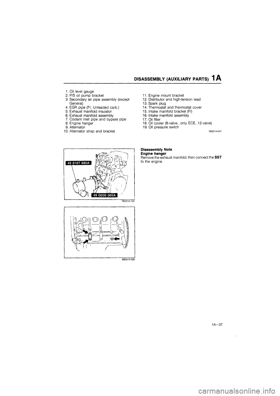
1. Oil level gauge
2. P/S oil pump bracket
3. Secondary air pipe assembly (except
General)
4. EGR pipe (Fl, Unleaded carb.)
5. Exhaust manifold insulator
6. Exhaust manifold assembly
7. Coolant inlet pipe and bypass pipe
8. Engine hanger
9. Alternator
10. Alternator strap and bracket
11. Engine mount bracket
12. Distributor and high-tension lead
13. Spark plug
14. Thermostat and thermostat cover
15. Intake manifold bracket (Fl)
16. Intake manifold assembly
17. Oil filter
18. Oil cooler (8-valve...only ECE, 12-valve)
19. Oil pressure switch
76G01A-047
Disassembly Note
Engine hanger
Remove the exhaust manifold; then connect the SST
to the engine.
76G01A-120
69G01X-000
1A—37
Page 121 of 1865
ASSEMBLY (AUXILIARY PARTS) 1 A
86U01X-171
76G01A-090
76G01A-091
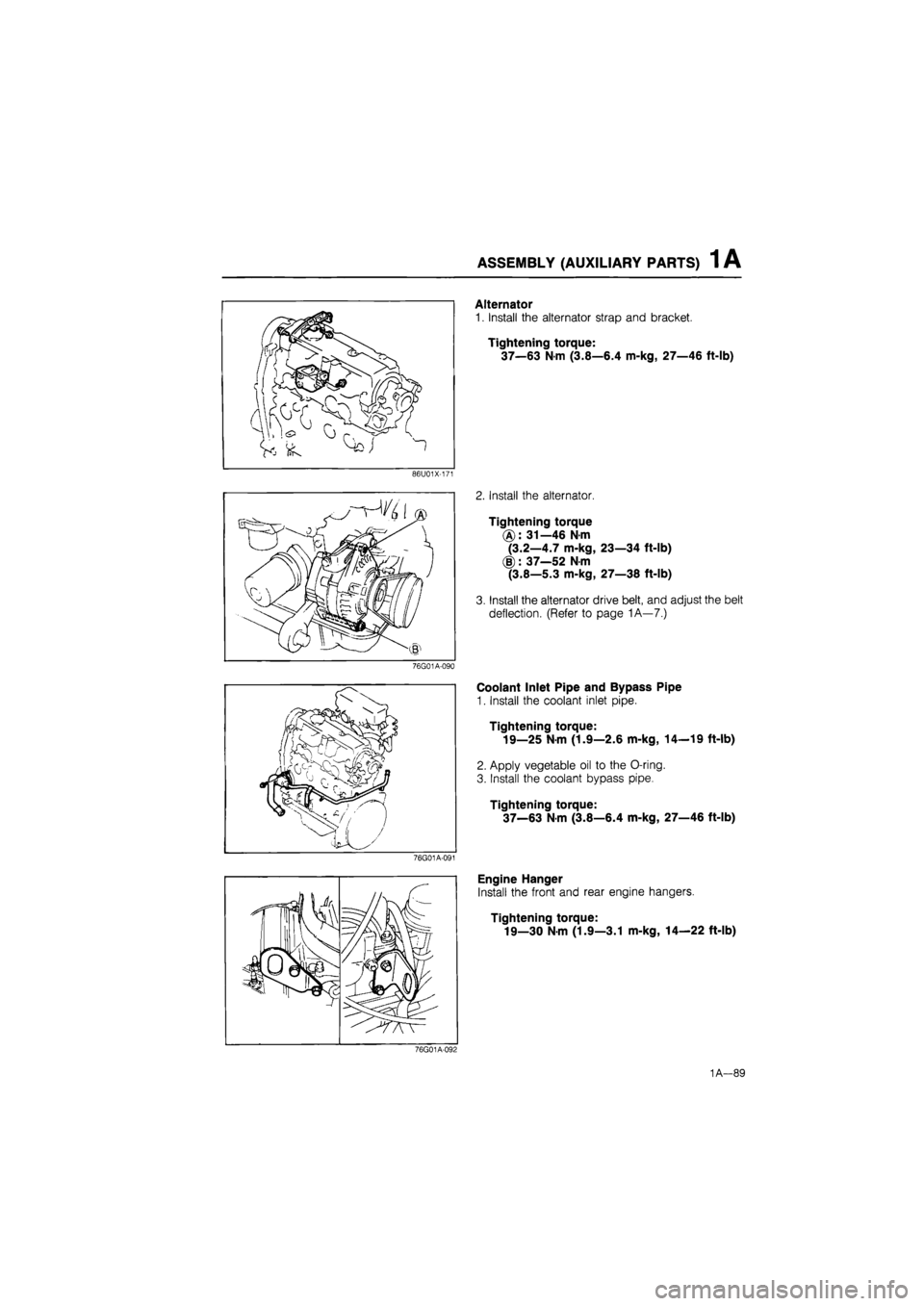
Alternator
1. Install the alternator strap and bracket.
Tightening torque:
37—63 Nm (3.8—6.4 m-kg, 27—46 ft-lb)
2. Install the alternator.
Tightening torque
(A): 31—46 Nm
(3.2—4.7 m-kg, 23—34 ft-lb)
(§): 37—52 N-m
(3.8—5.3 m-kg, 27—38 ft-lb)
3. Install the alternator drive belt, and adjust the belt
deflection. (Refer to page 1A—7.)
Coolant Inlet Pipe and Bypass Pipe
1. Install the coolant inlet pipe.
Tightening torque:
19—25 N-m (1.9—2.6 m-kg, 14—19 ft-lb)
2. Apply vegetable oil to the O-ring.
3. Install the coolant bypass pipe.
Tightening torque:
37—63
N
m (3.8—6.4 m-kg, 27—46 ft-lb)
Engine Hanger
Install the front and rear engine hangers.
Tightening torque:
19—30 N-m (1.9—3.1 m-kg, 14—22 ft-lb)
76G01A-092
1A—89
Page 129 of 1865
INSTALLATION 1A
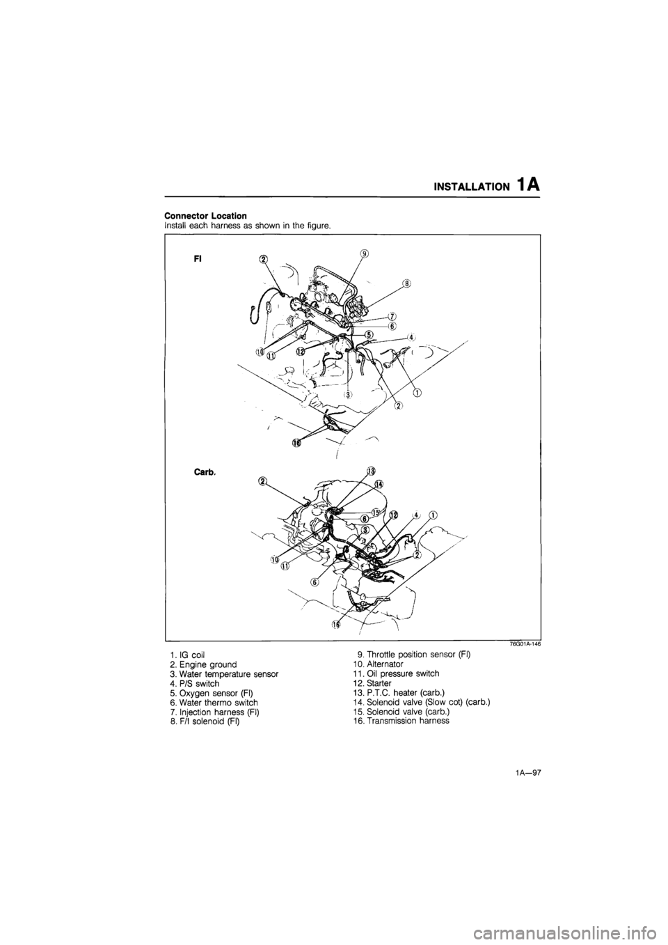
Connector Location
Install each harness as shown in the figure.
1. IG coil
2. Engine ground
3. Water temperature sensor
4. P/S switch
5. Oxygen sensor (Fl)
6. Water thermo switch
7. Injection harness (Fl)
8. F/l solenoid (Fl)
76G01A-146
9. Throttle position sensor (Fl)
10. Alternator
11. Oil pressure switch
12. Starter
13. P.T.C. heater (carb.)
14. Solenoid valve (Slow cot) (carb.)
15. Solenoid valve (carb.)
16. Transmission harness
1A—97
Page 135 of 1865
TROUBLESHOOTING GUIDE 1 B
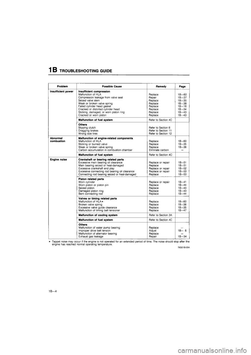
Problem Possible Cause Remedy Page
Insufficient power Insufficient compression Malfunction of HLA Compression leakage from valve seat Seized valve stem Weak or broken valve spring Failed cylinder head gasket Cracked or distorted cylinder head Sticking, damaged, or worn piston ring Cracked or worn piston
Replace Repair
Replace
Replace Replace Replace Replace Replace
1B—60 1B—37 1B—35 1B—38 1B-16 1B—34 1B—43 1B—43
Malfunction of fuel system Refer to Section 4C
Others Slipping clutch Dragging brakes Wrong size tires
Refer to Section 6 Refer to Section 11 Refer to Section 12
Abnormal combustion Malfunction of engine-related components Malfunction of HLA Sticking or burned valve
Weak or broken valve spring Carbon accumulation in combustion chamber
Replace Replace Replace
Eliminate carbon
1B-60
1B-35
1B—38
Malfunction of fuel system Refer to Section 4C
Engine noise Crankshaft or bearing related parts
Excessive main bearing oil clearance Main bearing seized or heat-damaged Excessive crankshaft end play Excessive connecting rod bearing oil clearance Connecting rod bearing seized or heat-damaged
Replace or repair Replace
Replace or repair Replace or repair Replace
1B-51 1B—51 1B—52 1B—53 1B—53
Piston related parts
Worn cylinder Worn piston or piston pin Seized piston Damaged piston ring Bent connecting rod
Replace or repair
Replace
Replace Replace Replace
1B—41 1B-44 1B—43 1B—43 1B-44
Valves or timing related parts Malfunction of HLA* Broken valve spring Excessive valve guide clearance Malfunction of timing belt tensioner
Replace Replace Replace Replace
1B-60 1B—38 1B—35 1B—47
Malfunction of cooling system Refer to Section 3A
Malfunction of fuel system Refer to Section 4C
Others Malfunction of water pump bearing Improper drive belt tension Malfunction of alternator bearing Exhaust gas leakage
Replace Adjust Replace Repair
1B— 6
1B—34
* Tappet noise may occur if the engine is not operated for an extended period of time. The noise should stop after the engine has reached normal operating temperature. 76G01B-004
1B—4
Page 137 of 1865
1B TUNE-UP PROCEDURE 1 B
86U01X-008
Coolant Level (Cold engine)
1. Check that the coolant level is near the radiator inlet
port.
2. Check that the level in the coolant reservoir is be-
tween the FULL and LOW marks.
Add coolant if necessary.
Warning
a) Never remove the radiator cap while the en-
gine is hot.
b) Wrap a thick cloth around the cap and care-
fully remove it.
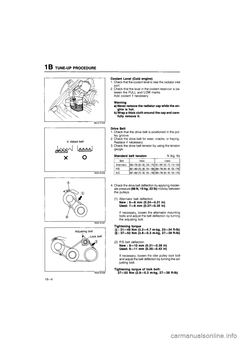
Drive Belt
1. Check that the drive belt is positioned in the pul-
ley groove.
2. Check the drive belt for wear, cracks, or fraying.
Replace if necessary.
3. Check the drive belt tension by using the tension
gauge.
Standard belt tension N (kg, lb)
76G01B-006
Belt New Used
Alternator 589-785 (60-80, 132-176) 491-687 (50-70, 110-154)
P/S 687-883 (70-90,154-198) 589-785 (60-80.132-176)
A/C 687-883 (70-90,154-198) 589-785 (60-80,132-176)
76G01B-007
Adjusting bolt
76G01B-008
4. Check the drive belt deflection by applying moder-
ate pressure (98 N, 10 kg, 22 lb) midway between
the pulleys.
(1) Alternator belt deflection
New : 6—8 mm (0.24—0.31 in)
Used: 7—9 mm (0.27—0.35 in)
If necessary, loosen the alternator mounting
bolts and adjust the belt deflection by turning
the adjusting bolt.
Tightening torque
®: 31—46 Nm (3.2—4.7 m-kg, 23—34 ft-lb)
(§): 37—52 Nm (3.8—5.3 m-kg, 27—38 ft-lb)
(2) P/S belt deflection
New : 8—10 mm (0.31—0.39 in)
Used: 9—11 mm (0.35—0.43 in)
If necessary, loosen the idler pulley lock bolt
and adjust the belt deflection by turning the ad-
justing bolt.
Tightening torque of lock bolt:
37—52 N-m (3.8—5.3 m-kg, 27—38 ft-lb)
1B—6
Page 156 of 1865
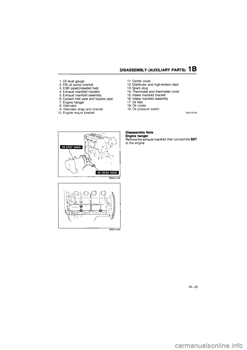
DISASSEMBLY (AUXILIARY PARTS) 1 B
1. Oil level gauge
2. P/S oil pump bracket
3. EGR pipe(Unleaded fuel)
4. Exhaust manifold insulator
5. Exhaust manifold assembly
6. Coolant inlet pipe and bypass pipe
7. Engine hanger
8. Alternator
9. Alternator strap and bracket
10. Engine mount bracket
11. Center cover
12. Distributor and high-tension lead
13. Spark plug
14. Thermostat and thermostat cover
15. Intake manifold bracket
16. Intake manifold assembly
17. Oil filter
18. Oil cooler
19. Oil pressure switch
76G01B-039
49 0107 680A Irf^Ys'^
,v,, I
' ir
>
49 G030 D05A
76G01A-120
Disassembly Note
Engine hanger
Remove the exhaust manifold; then connect the SST
to the engine.
69G01X-000
1B—25
Page 202 of 1865
ASSEMBLY (AUXILIARY PARTS) 1 B
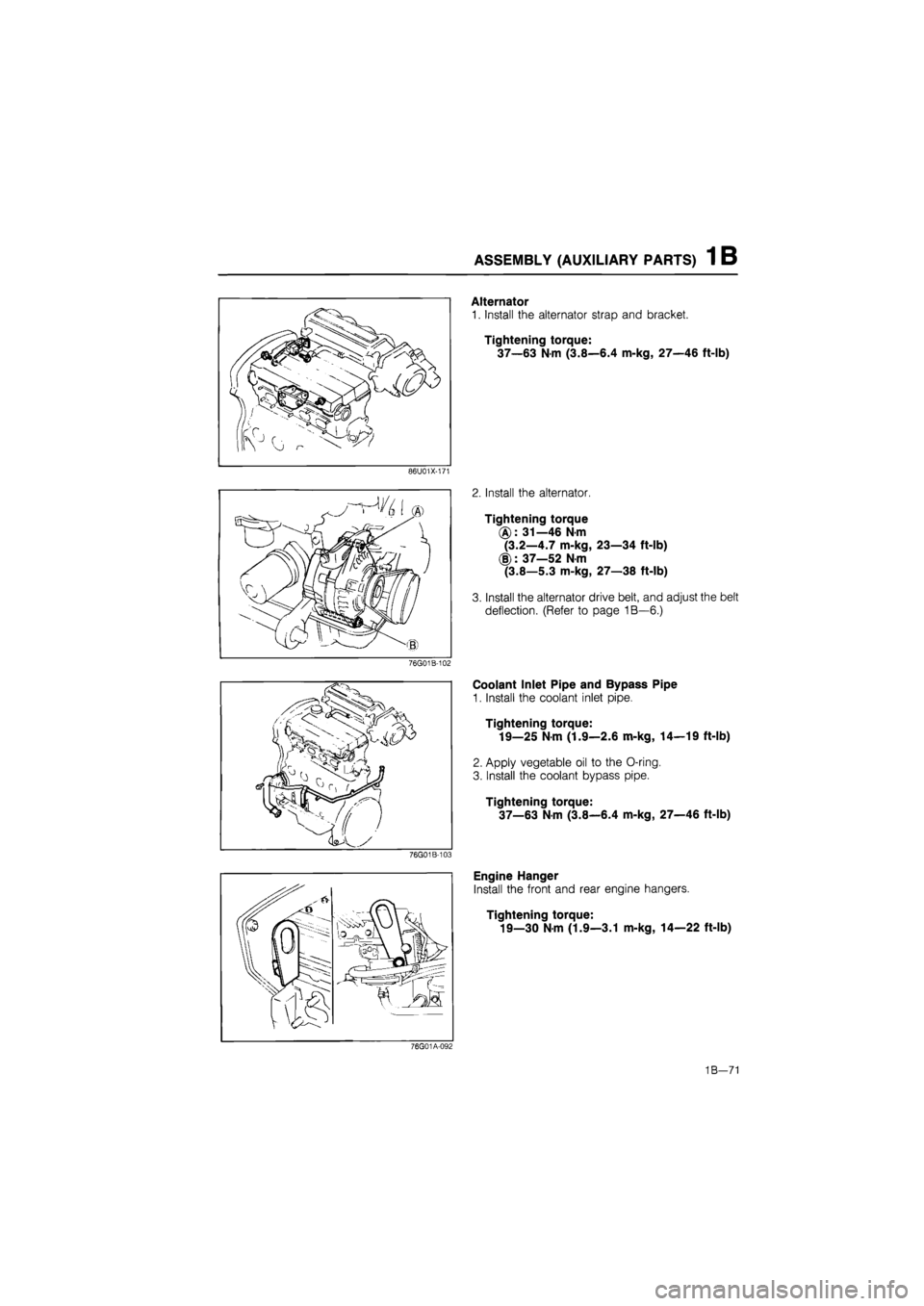
Alternator
1. Install the alternator strap and bracket.
Tightening torque:
37—63 Nm (3.8—6.4 m-kg, 27—46 ft-lb)
86U01X-171
Install the alternator.
Tightening torque
(g): 31—46 N-m
(3.2—4.7 m-kg, 23—34 ft-lb)
(§): 37—52 N-m
(3.8—5.3 m-kg, 27—38 ft-lb)
Install the alternator drive belt, and adjust the belt
deflection. (Refer to page 1B—6.)
76G01B-102
Coolant Inlet Pipe and Bypass Pipe
1. Install the coolant inlet pipe.
Tightening torque:
19—25 N-m (1.9—2.6 m-kg, 14—19 ft-lb)
2. Apply vegetable oil to the O-ring.
3. Install the coolant bypass pipe.
Tightening torque:
37—63 N-m (3.8—6.4 m-kg, 27—46 ft-lb)
Engine Hanger
Install the front and rear engine hangers.
Tightening torque:
19—30 N-m (1.9—3.1 m-kg, 14—22 ft-lb)
76G01A-092
1B—71