warning light MAZDA 626 1987 Owner's Manual
[x] Cancel search | Manufacturer: MAZDA, Model Year: 1987, Model line: 626, Model: MAZDA 626 1987Pages: 1865, PDF Size: 94.35 MB
Page 1468 of 1865
1 1 ANTI-LOCK BRAKE SYSTEM (ABS)
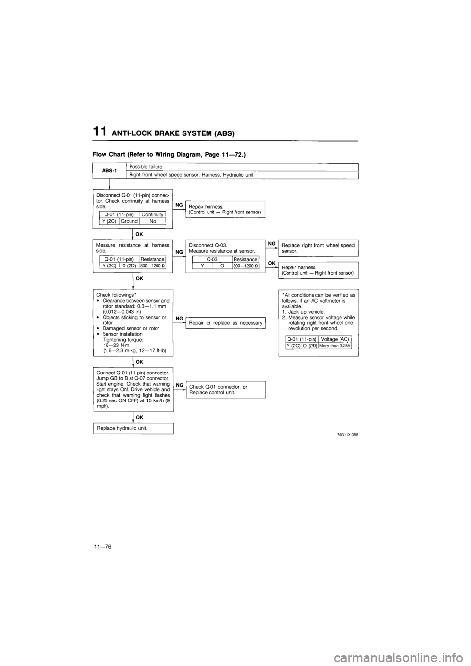
Flow Chart (Refer to Wiring Diagram, Page 11—72.)
ABS-1
Possible failure
Right front wheel speed sensor, Harness, Hydraulic unit
Disconnect Q-01 (11-pin) connec-tor. Check continuity
at
harness side.
Q-01 (11-pin)
I
Continuity
Y (2C) Ground No
OK
Measure resistance
at
harness side.
Q-01 (11-pin) Resistance
Y (2C)
i 0
(2D) 800—1200
Q
OK
NG
Repair harness.
(Control unit — Right front sensor)
NG
Disconnect Q-03. Measure resistance
at
sensor.
Q-03 Resistance
Y
[ O
800—1200 Q
NG
Replace right front wheel speed sensor.
OK
Repair harness.
(Control unit — Right front sensor)
Check followings*
• Clearance between sensor and rotor standard: 0.3—1.1
mm
(0.012-0.043
in)
• Objects sticking
to
sensor
or
rotor
• Damaged sensor
or
rotor
• Sensor installation Tightening torque: 16-23 N-m (1.6-2.3 m-kg, 12—17 ft-lb)
OK
Connect Q-01 (11-pin) connector. Jump GB
to B at
Q-07 connector. Start engine. Check that warning light stays ON. Drive vehicle and check that warning light flashes (0.25 sec ON OFF)
at 15
km/h
(9
mph).
NG
Repair
or
replace
as
necessary
* All conditions can
be
verified
as
follows,
if an AC
voltmeter
is
available. 1. Jack
up
vehicle. 2. Measure sensor voltage while rotating right front wheel
one
revolution
per
second.
Q-01 (11-Din) Voltage (AC)
Y (2C) O (2D) More than 0.25V
NG
Check Q-01 connector,
or
Replace control unit.
OK
Replace hydraulic unit.
76G11X-055
11—76
Page 1469 of 1865
ANTI-LOCK BRAKE SYSTEM (ABS) 1 1
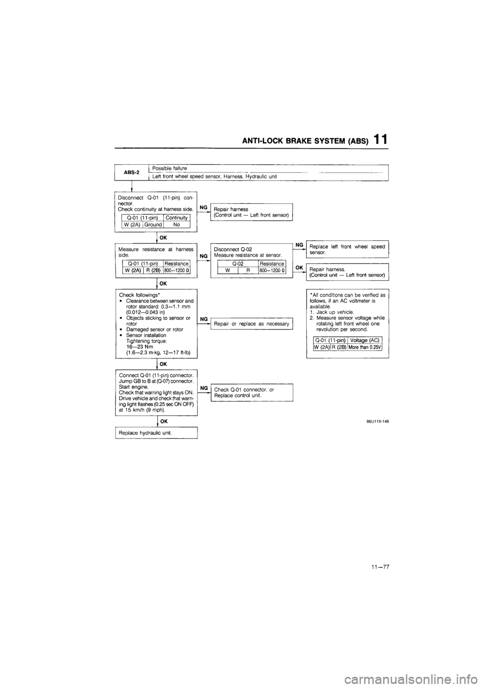
ABS-2
Possible failure
Left front wheel speed sensor, Harness, Hydraulic unit
Disconnect
Q-01
(11-pin)
con-
nector.
Check continuity
at
harness side.
Q-01 (11-pin) Continuity
W (2A) Ground No
OK
Measure side.
Q-01 (11-pin) Resistance
W (2A) R (2B) 800-1200
fl
OK
Connect Q-01 (11-pin) connector. Jump GB
to B
at (Q-07) connector. Start engine.
Check that warning light stays ON. Drive vehicle and check that warn-ing light flashes (0.25 sec ON OFF) at
15
km/h
(9
mph).
NG
Repair harness (Control unit
—
Left front sensor)
resistance
at
harness
NG
Disconnect Q-02 Measure resistance
at
sensor.
Q-02 Resistance
W
| R
800-1200
0
OK
Check followings*
• Clearance between sensor and rotor standard: 0.3—1.1
mm
(0.012-0.043
in)
• Objects sticking
to
sensor
or
rotor • Damaged sensor
or
rotor
• Sensor installation Tightening torque: 16-23 N m
(1.6—2.3 m-kg, 12-17 ft-lb)
NG
OK
NG
Repair
or
replace
as
necessary
NG
Check Q-01 connector,
or
Replace control unit.
OK
Replace hydraulic unit.
Replace left front wheel speed
sensor.
Repair harness.
(Control unit
—
Left front sensor)
"All conditions can
be
verified
as
follows,
if an AC
voltmeter
is
available. 1. Jack
up
vehicle. 2. Measure sensor voltage while rotating left front wheel
one
revolution
per
second.
Q-01 (11-pin) Voltage (AC)
W (2 A)
|
R (2B) More than
0
25V
86U11X-146
11-77
Page 1470 of 1865
1 1 ANTI-LOCK BRAKE SYSTEM (ABS)
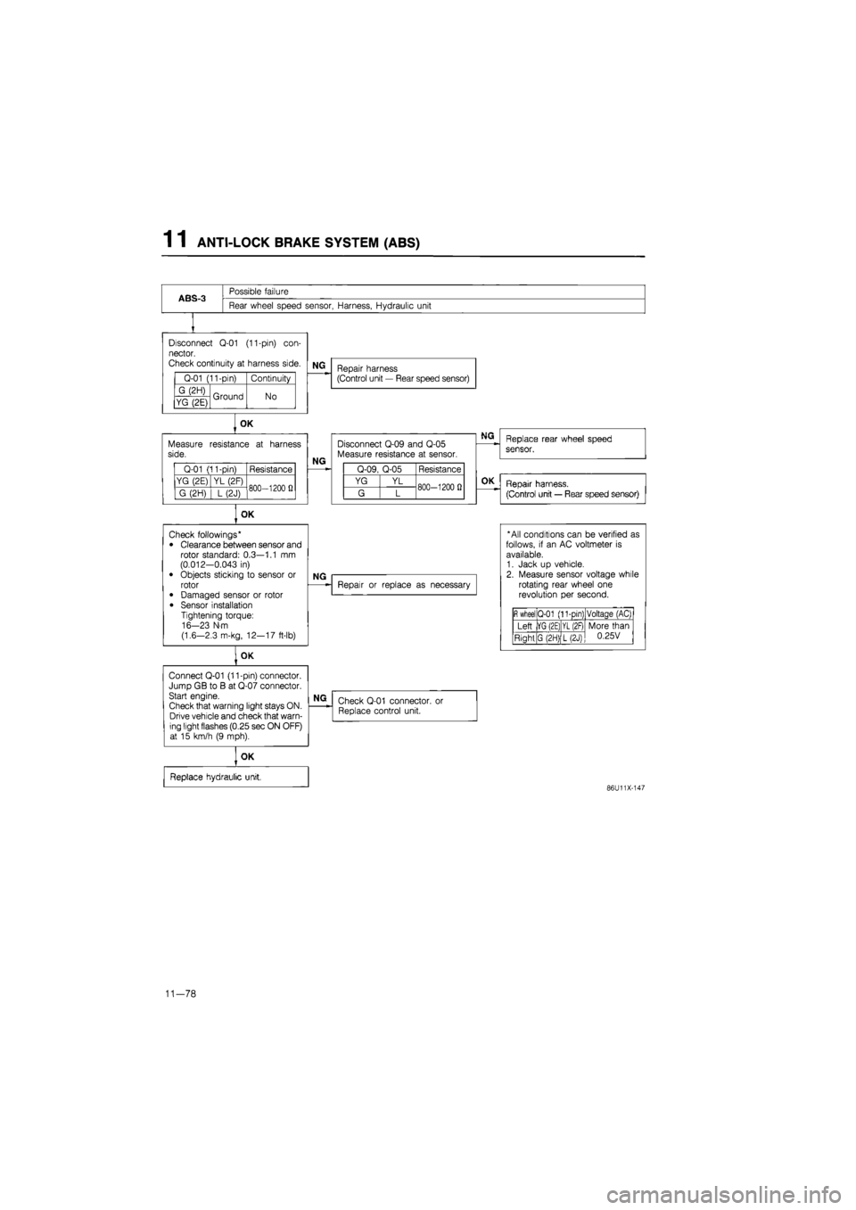
ABS-3
Possible failure
Rear wheel speed sensor, Harness, Hydraulic unit
Disconnect
Q-01
(11-pin)
con-
nector.
Check continuity
at
harness side.
Q-01 (11-pin) Continuity
G (2H) Ground No YG (2E) Ground No
Measure side.
Q-01 (11-pin) Resistance
YG (2E) YL (2F) 800—1200
fi
G (2H)
] L
(2J) 800—1200
fi
OK
Connect Q-01 (11-pin) connector. Jump GB
to B at
Q-07 connector. Start engine.
Check that warning light stays ON. Drive vehicle and check that warn-ing light flashes (0.25 sec ON OFF) at
15
km/h
(9
mph).
NG
Repair harness (Control unit
—
Rear speed sensor)
OK
resistance
at
harness
NG
Disconnect Q-09 and Q-05 Measure resistance
at
sensor.
Q-09, Q-05 Resistance
YG YL 800-1200
0
G L 800-1200
0
OK
Check followings* • Clearance between sensor and rotor standard: 0.3—1.1
mm
(0.012-0.043
in)
• Objects sticking
to
sensor
or
rotor
• Damaged sensor
or
rotor
• Sensor installation Tightening torque: 16-23 N-m
(1.6—2.3 m-kg, 12—17 ft-lb)
NG
Repair
or
replace
as
necessary
NG
Check Q-01 connector. Replace control unit.
or
OK
Replace hydraulic unit,
Replace rear wheel speed
sensor.
OK
Repair harness.
(Control unit
—
Rear speed sensor)
* All conditions can
be
verified
as
follows,
if an AC
voltmeter
is
available. 1. Jack
up
vehicle. 2. Measure sensor voltage while rotating rear wheel
one
revolution
per
second.
fi
wheel Q-01 (11-pin) Voltaqe (AC)
Left |YG (2E) YL (2F) More than 0.25V Right G (2H) L(2J)
More than 0.25V
86U11X-147
11-78
Page 1472 of 1865
1 1 ANTI-LOCK BRAKE SYSTEM (ABS)
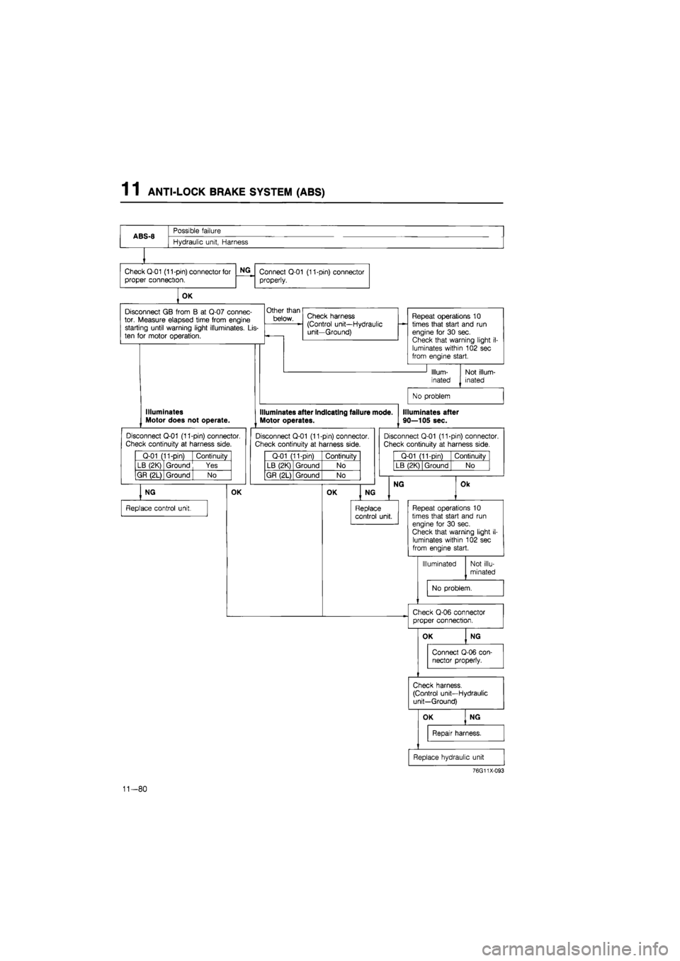
ABS-8
Possible failure
ABS-8
Hydraulic unit, Harness
Check Q-01 (11-pin) connector for
proper connection.
NG
Connect Q-01 (11-pin) connector
properly.
OK
Disconnect
GB
from
B at
Q-07 connec-tor. Measure elapsed time from engine starting until warning light illuminates.
Lis-
ten
for
motor operation.
Other than
below. Check harness (Control unit—Hydraulic unit—Ground)
Repeat operations
10
times that start and
run
engine
for 30
sec. Check that warning light
i
luminates within 102 sec from engine start.
Illum-
inated
Not illum-inated
No problem
Illuminates Motor does not operate.
Disconnect Q-01 (11-pin) connector.
Check continuity
at
harness side.
Q-01 (11-pin) Continuity
LB (2K) Ground Yes
GR (2L) Ground
| No
NG
Replace control unit.
OK
Illuminates after indicating failure mode.
Motor operates.
Disconnect Q-01 (11-pin) connector. Check continuity
at
harness side.
Q-01 (11-pin) Continuity
LB (2K) Ground No
GR (2L) Ground No
OK
Illuminates after
90—105 sec.
Disconnect Q-01 (11-pin) connector.
Check continuity
at
harness side.
Q-01 (11-pin) Continuity
LB (2K) Ground No
NG
NG
Replace control unit.
Ok
Repeat operations
10
times that start and
run
engine
for 30
sec. Check that warning light
il-
luminates within 102 sec from engine start.
Illuminated Not illu-
minated
No problem.
Check Q-06 connector proper connection.
76G11X-093
11-80
Page 1478 of 1865
1 1 ANTI-LOCK BRAKE SYSTEM (ABS)
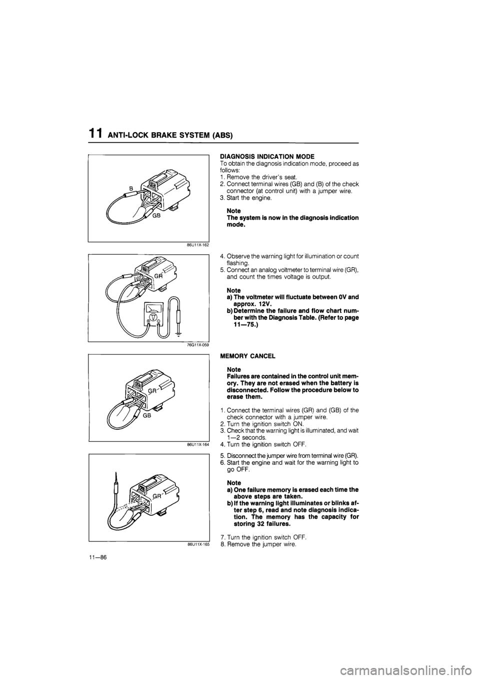
DIAGNOSIS INDICATION MODE
To obtain the diagnosis indication mode, proceed as
follows:
1. Remove the driver's seat.
2. Connect terminal wires (GB) and (B) of the check
connector (at control unit) with a jumper wire.
3. Start the engine.
Note
The system is now in the diagnosis indication
mode.
86U11X-162
4. Observe the warning light for illumination or count
flashing.
5. Connect an analog voltmeter to terminal wire (GR),
and count the times voltage is output.
Note
a) The voltmeter will fluctuate between OV and
approx. 12V.
b) Determine the failure and flow chart num-
ber with the Diagnosis Table. (Refer to page
11—75.)
76G11X-059
86U11X-164
86U11X-165
MEMORY CANCEL
Note
Failures are contained in the control unit mem-
ory. They are not erased when the battery is
disconnected. Follow the procedure below to
erase them.
1. Connect the terminal wires (GR) and (GB) of the
check connector with a jumper wire.
2. Turn the ignition switch ON.
3. Check that the warning light is illuminated, and wait
1—2 seconds.
4. Turn the ignition switch OFF.
5. Disconnect the jumper wire from terminal wire (GR).
6. Start the engine and wait for the warning light to
go OFF.
Note
a) One failure memory is erased each time the
above steps are taken.
b) If the warning light illuminates or blinks af-
ter step 6, read and note diagnosis indica-
tion. The memory has the capacity for
storing 32 failures.
7. Turn the ignition switch OFF.
8. Remove the jumper wire.
11-86
Page 1479 of 1865
ANTI-LOCK BRAKE SYSTEM (ABS) 1 1
86U11X-1C
Q-08
Q-08
Fail-safe relay
B B BG
(Q-08)(Q-09)
V
BL BR
Motor relay
B BR (Q-09)
LO RY
View from male-pin side
86U11X-167
76G11X-096
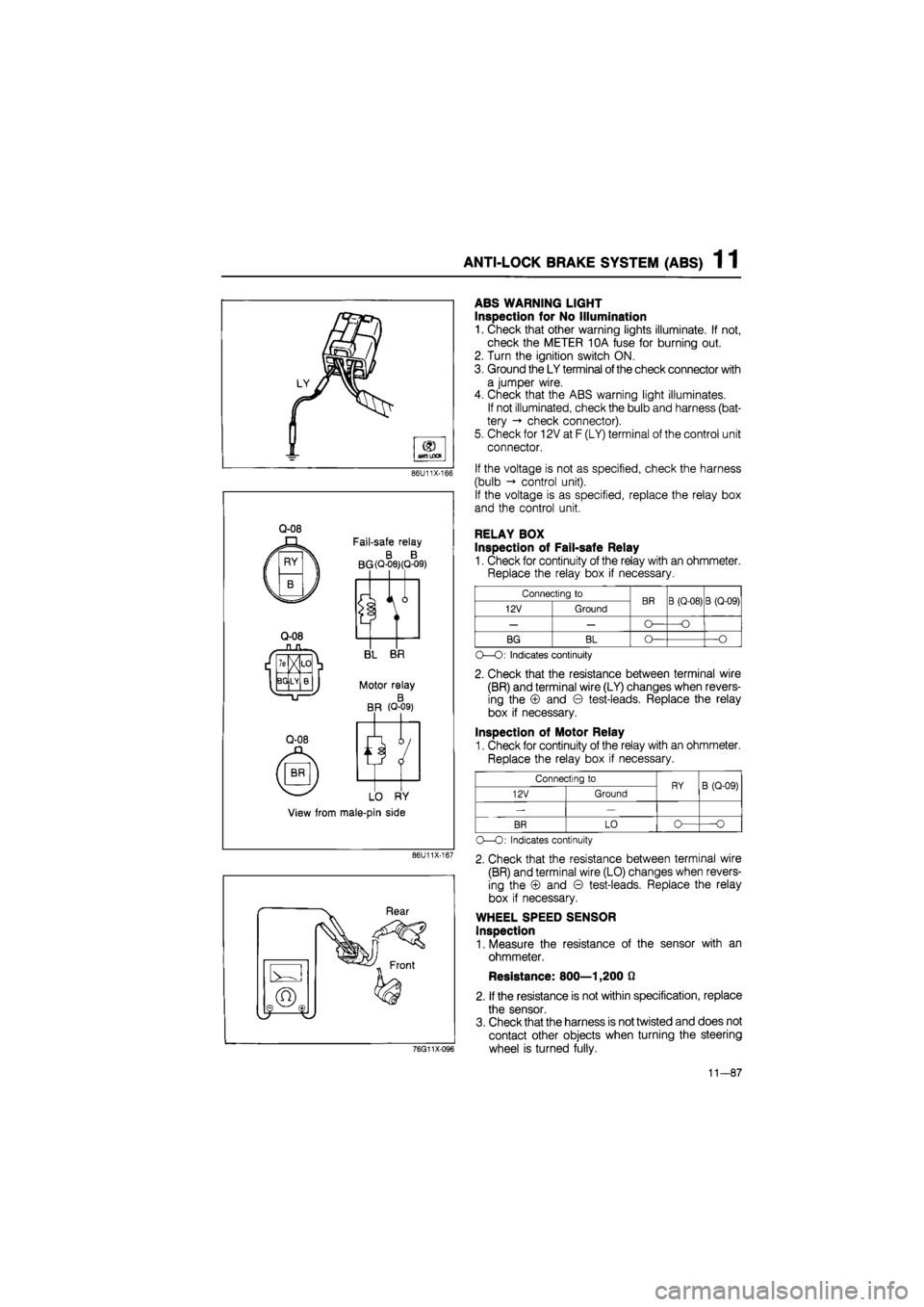
ABS WARNING LIGHT
Inspection for No Illumination
1. Check that other warning lights illuminate. If not,
check the METER 10A fuse for burning out.
2. Turn the ignition switch ON.
3. Ground the LY terminal
of
the check connector with
a jumper wire.
4. Check that the ABS warning light illuminates.
If not illuminated, check the bulb and harness (bat-
tery -» check connector).
5. Check for 12V at F (LY) terminal of the control unit
connector.
If the voltage is not as specified, check the harness
(bulb control unit).
If the voltage is as specified, replace the relay box
and the control unit.
RELAY BOX
Inspection of Fail-safe Relay
1. Check for continuity of the relay with an ohmmeter.
Replace the relay box if necessary.
Connecting to BR B (Q-08) B (Q-09) 12V Ground BR B (Q-08) B (Q-09)
— — O— —O
BG BL O— —O
O—O: Indicates continuity
2. Check that the resistance between terminal wire
(BR) and terminal wire (LY) changes when revers-
ing the © and © test-leads. Replace the relay
box if necessary.
Inspection of Motor Relay
1. Check for continuity of the relay with an ohmmeter.
Replace the relay box if necessary.
Connecting to RY B (Q-09) 12V Ground RY B (Q-09)
-—
BR LO o— O
O—O: Indicates continuity
2. Check that the resistance between terminal wire
(BR) and terminal wire (LO) changes when revers-
ing the © and © test-leads. Replace the relay
box if necessary.
WHEEL SPEED SENSOR
Inspection
1. Measure the resistance of the sensor with an
ohmmeter.
Resistance: 800—1,200 0
2. If the resistance is not within specification, replace
the sensor.
3. Check that the harness is not twisted and does not
contact other objects when turning the steering
wheel is turned fully.
11-87
Page 1487 of 1865
ANTI-LOCK BRAKE SYSTEM (ABS) 1 1
86U11X-190
86U11X-191
76G11X098
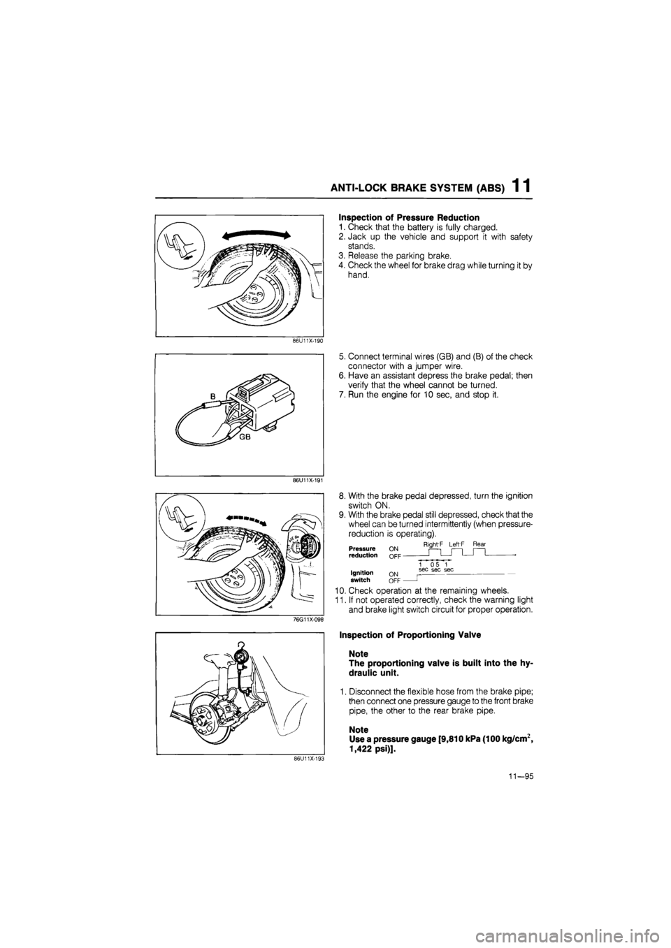
Inspection of Pressure Reduction
1. Check that the battery is fully charged.
2. Jack up the vehicle and support it with safety
stands.
3. Release the parking brake.
4. Check the wheel for brake drag while turning it by
hand.
5. Connect terminal wires (GB) and (B) of the check
connector with a jumper wire.
6. Have an assistant depress the brake pedal; then
verify that the wheel cannot be turned.
7. Run the engine for 10 sec, and stop it.
8. With the brake pedal depressed, turn the ignition
switch ON.
9. With the brake pedal still depressed, check that the
wheel can be turned intermittently (when pressure-
reduction is operating).
Right'F Left F Rear Pressure reduction
Ignition switch ON OFF
1 05 1 sec sec sec
J
10. Check operation at the remaining wheels.
11. If not operated correctly, check the warning light
and brake light switch circuit for proper operation.
Inspection of Proportioning Valve
Note
The proportioning valve is built into the hy-
draulic unit.
1. Disconnect the flexible hose from the brake pipe;
then connect one pressure gauge to the front brake
pipe, the other to the rear brake pipe.
Note
Use a pressure gauge [9,810 kPa (100 kg/cm2,
1,422 psi)].
86U11X-193
11—95
Page 1491 of 1865
ANTI-LOCK BRAKE SYSTEM (ABS) 1 1
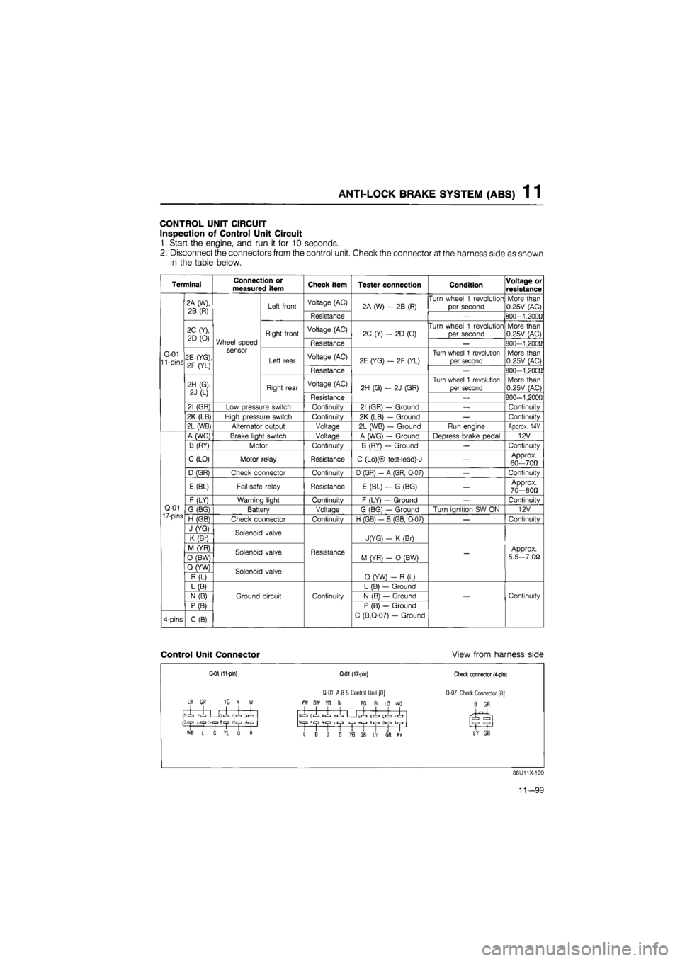
CONTROL UNIT CIRCUIT
Inspection of Control Unit Circuit
1. Start the engine, and run it for 10 seconds.
2. Disconnect the connectors from the control unit. Check the connector at the harness side as shown
in the table below.
Terminal Connection or measured item Check item Tester connection Condition Voltage or
resistance
Q-01 11 -pins
2A (W),
2B (R)
Wheel speed sensor
Left front Voltage (AC) 2A (W)
- 2B
(R) Turn wheel
1
revolution
per second More than 0.25V (AC)
Q-01 11 -pins
2A (W),
2B (R)
Wheel speed sensor
Left front
Resistance
2A (W)
- 2B
(R)
—
800-1.2000
Q-01 11 -pins
2C (Y),
2D
(0)
Wheel speed sensor
Right front Voltage (AC) 2C (Y)
-
2D (0) Turn wheel
1
revolution
per second More than 0.25V (AC)
Q-01 11 -pins
2C (Y),
2D
(0)
Wheel speed sensor
Right front
Resistance
2C (Y)
-
2D (0)
—
800-1,2000
Q-01 11 -pins 2E (YG),
2F (YL)
Wheel speed sensor
Left rear Voltage (AC) 2E (YG)
- 2F
(YL) Turn wheel
1
revolution
per second More than 0.25V (AC) Q-01 11 -pins 2E (YG),
2F (YL)
Wheel speed sensor
Left rear
Resistance
2E (YG)
- 2F
(YL)
—
800-1,200G
Q-01 11 -pins
2H (G).
2J
(L)
Wheel speed sensor
Right rear Voltage (AC) 2H (G)
- 2J
(GR)
Turn wheel
1
revolution
per second More than 0.25V (AC)
Q-01 11 -pins
2H (G).
2J
(L)
Wheel speed sensor
Right rear
Resistance
2H (G)
- 2J
(GR)
_
800-1,200fl
Q-01 11 -pins
21 (GR) Low pressure switch Continuity 21 (GR)
-
Ground
—
Continuity
Q-01 11 -pins
2K (LB) High pressure switch Continuity 2K (LB)
-
Ground
—
Continuity
Q-01 11 -pins
2L (WB) Alternator output Voltage 2L (WB)
-
Ground Run engine Approx.
14V
Q-01
17-pins
A (WG) Brake light switch Voltage A (WG)
-
Ground Depress brake pedal 12V
Q-01
17-pins
B (RY) Motor Continuity B (RY)
—
Ground
—
Continuity
Q-01
17-pins
C (LO) Motor relay Resistance C (Lo)(© test-lead)-J
—
Approx. 60—700
Q-01
17-pins
D (GR) Check connector Continuity D (GR)
- A
(GR, Q-07)
—
Continuity
Q-01
17-pins
E (BL) Fail-safe relay Resistance E (BL)
- G
(BG)
—
Approx. 70-800
Q-01
17-pins
F (LY) Warning light Continuity F (LY)
-
Ground
—
Continuitv Q-01
17-pins G (BG) Battery Voltage G (BG)
—
Ground Turn ianition
SW ON
12V Q-01
17-pins H (GB) Check connector Continuitv H (GB)
- B
(GB. Q-07)
—
Continuitv
Q-01
17-pins
J (YG) Solenoid valve
Resistance
JfYG)
- K
(Br)
-
Approx.
5.5—7.00
Q-01
17-pins
K (Br) Solenoid valve
Resistance
JfYG)
- K
(Br)
-
Approx.
5.5—7.00
Q-01
17-pins
M (YR) Solenoid valve Resistance M (YR)
- 0
(BW)
-
Approx.
5.5—7.00
Q-01
17-pins
0 (BW) Solenoid valve Resistance M (YR)
- 0
(BW)
-
Approx.
5.5—7.00
Q-01
17-pins
Q (YW) Solenoid valve
Resistance
Q (YW)
- R
(L)
-
Approx.
5.5—7.00
Q-01
17-pins
R (L) Solenoid valve
Resistance
Q (YW)
- R
(L)
-
Approx.
5.5—7.00
Q-01
17-pins
L (B)
Ground circuit Continuity
L (B)
—
Ground
Continuity
Q-01
17-pins
N
(B)
Ground circuit Continuity N (B)
—
Ground Continuity
Q-01
17-pins
P (B)
Ground circuit Continuity
P (B)
—
Ground
C (B.Q-07)
-
Ground
Continuity
4-pins C(B)
Ground circuit Continuity
P (B)
—
Ground
C (B.Q-07)
-
Ground
Continuity
Control Unit Connector View from harness side
Q-01 (11-pin)
LB
GR YG Y W
>1 ,1 U;.l Ki -X
1 L G VL rf
Q-01 (17-pin)
Q-01 ABS Control Unit [R]
YW BW YR Br 8G BL LO WG
icL olL
MIL
ICL G(=L tl ij^" llyl
>1
CjJ
Lt|J JCjJ fiC|3 H«|3
L B B B ffi SB L* GS RY
Check connector (4-pin)
Q-07 Check Connector [RJ
B GR
LY GB
86U11X-199
11—99
Page 1656 of 1865

15
BODY ELECTRICAL SYSTEM
INTRODUCTION 15- 2 HOW TO USE THIS SECTION 15— 2 ELECTRICAL TROUBLESHOOTING TOOLS 15- 2 PRECAUTION 15— 3 ELECTRICAL SYMBOLS 15- 6 LOCATION OF UNIT, RELAY AND SWITCH 15- 7
STRUCTURAL VIEW 15— 7 MAIN FUSE BLOCK 15- 9 STRUCTURAL VIEW 15— 9 REPLACEMENT 15—10 IGNITION SWITCH 15—10
INSPECTION 15— 10 JOINT BOX AND FUSE 15—11
STRUCTURAL VIEW 15—11
COMBINATION SWITCH 15-12 STRUCTURAL VIEW 15- 12 INSPECTION 15— 13 CLUSTER SWITCH 15—17 STRUCTURAL VIEW 15— 17 INSPECTION OF ROCKER TYPE 15— 19
INSPECTION OF PUSH TYPE 15— 20 METER 15— 22 STRUCTURAL VIEW 15— 22 DISASSEMBLY AND ASSEMBLY 15— 23
TROUBLESHOOTING 15— 24 INSPECTION OF ANALOG METER .... 15— 26 INSPECTION OF DIGITAL METER 15— 27
INSPECTION OF METER SENDER 15— 29 WARNING LIGHT AND SENDER 15- 31 CIRCUIT DIAGRAM 15— 31
TROUBLESHOOTING 15- 32 INSPECTION 15— 39 CENTRAL PROCESSING UNIT 15— 41 STRUCTURAL VIEW 15— 41 FUNCTIONS 15- 41 CIRCUIT DIAGRAM 15— 42 REMOVAL AND INSTALLATION 15— 43
ON-VEHICLE INSPECTION 15- 43 TURN AND HAZARD LIGHT 15- 44 STRUCTURAL VIEW 15— 44 CIRCUIT DIAGRAM 15— 45
TROUBLESHOOTING 15- 46 INSPECTION 15— 47 STOP LIGHT 15— 48
STRUCTURAL VIEW 15— 48 CIRCUIT DIAGRAM 15— 49
TROUBLESHOOTING 15- 49 INSPECTION 15- 50 HORN 15— 52 STRUCTURAL VIEW 15— 52 CIRCUIT DIAGRAM 15— 52 TROUBLESHOOTING 15— 53 INSPECTION 15-53 HEADLIGHT 15— 54 CIRCUIT DIAGRAM 15— 54 TROUBLESHOOTING 15— 54 INSPECTION 15— 55 PANEL LIGHT CONTROL 15— 56 CIRCUIT DIAGRAM 15— 56
TROUBLESHOOTING 15_ 5fi INSPECTION 17 REAR WINDOW DEFROSTER ..i".'! 15- 58
STRUCTURAL VIEW 15-5fl CIRCUIT DIAGRAM 15_ «
TROUBLESHOOTING '.. 15_ 59
INSPECTION
15-60 POWER WINDOW 15-61 STRUCTURAL VIEW il_ «1 CIRCUIT DIAGRAM 15_ 62 TROUBLESHOOTING 15- «3 INSPECTION 15-66 REMOTE CONTROL MIRROR ........15- 69 STRUCTURAL VIEW 15-69 CIRCUIT DIAGRAM 15_ 69
TROUBLESHOOTING 15_ 70 INSPECTION 15_ 70 REAR WINDOW WIPER 15_ 71 STRUCTURAL VIEW 15-71 CIRCUIT DIAGRAM .'.'.'...' 15_ 72
TROUBLESHOOTING 15-73 INSPECTION 15-75 WINDSHIELD WIPER 15-76 STRUCTURAL VIEW ' ' 15— 7e
DISASSEMBLY AND ASSEMBLY OF WIPER MOTOR 15_ 76 CIRCUIT DIAGRAM 15-77 TROUBLESHOOTING " " 15— 70 INSPECTION 15-81 CRUISE CONTROL SYSTEM 15- 82 STRUCTURAL VIEW 15-82 CIRCUIT DIAGRAM 15-83 ON-VEHICLE INSPECTION \..\m 15- 84 INSPECTION 15-87 SLIDING SUNROOF 15-89 STRUCTURAL VIEW 15_ 89 CIRCUIT DIAGRAM i5_ 90
TROUBLESHOOTING 15— 91 INSPECTION 15_ 90 AUTO ADJUSTING SUSPENSION 15— 94
CIRCUIT DIAGRAM 15- 94
TROUBLESHOOTING GUIDE 15— 94
TROUBLESHOOTING 15— 94
INSPECTION 15-104
POWER DOOR LOCK 15-105
STRUCTURAL VIEW 15-105
CIRCUIT DIAGRAM 15-105
TROUBLESHOOTING 15-106 INSPECTION 15-107 AUDIO SYSTEM " 15_108 OUTLINE OF AUDIO SYSTEM 15-108 REAR CONNECTOR VIEW 15-109 ADJUSTMENT (MTR) 15—114 POWER ANTENNA 15-114 HEATER J
STRUCTURAL VIEW 15-116 AIR FLOW AT EACH MODE 15-117 RATE OF AIR FLOW 15-119 LEVER CONTROL TYPE 15-120 LOGICAL CONTROL
TYPE
15—121 LOGICON SWITCH 15—123
76G15X-001
Page 1677 of 1865

15 METER
METER
STRUCTURAL VIEW
DIGITAL ELECTRONIC DISPLAY METER
ANALOG DISPLAY METER
76G15X-007
1. Speedometer 5. Warning and indicator lights
2. Tachometer 6. Tripmeter
3. Water temperature gauge 7. Twin tripmeter change switch
4. Fuel gauge 8. Fuel garge scale change switch
15—22