check engine MAZDA 626 1987 Workshop Manual
[x] Cancel search | Manufacturer: MAZDA, Model Year: 1987, Model line: 626, Model: MAZDA 626 1987Pages: 1865, PDF Size: 94.35 MB
Page 1791 of 1865
16 OUTLINE
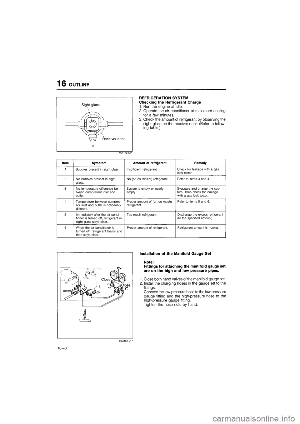
Sight glass
REFRIGERATION SYSTEM
Checking the Refrigerant Charge
1. Run the engine at idle.
2. Operate the air conditioner at maximum cooling
for a few minutes.
3. Check the amount of refrigerant by observing the
sight glass on the receiver-drier. (Refer to follow-
ing table.)
76G16X-005
Item Symptom Amount of refrigerant Remedy
1 Bubbles present
in
sight glass. Insufficient refrigerant. Check
for
leakage with
a gas
leak tester.
2 No bubbles present
in
sight
glass.
No
(or
insufficient) refrigerant. Refer
to
items
3
and
4.
3 No temperature difference
be-
tween compressor inlet and outlet.
System
is
empty
or
nearly empty. Evacuate and charge the sys-tem. Then check
for
leakage with
a
gas leak tester.
4 Temperature between compres-sor inlet and outlet
is
noticeably different.
Proper amount
of (or
too much) refrigerant. Refer
to
items
5
and
6.
5 Immediately after the
air
condi-tioner
is
turned off, refrigerant
in
sight glass stays clear.
Too much refrigerant. Discharge the excess refrigerant
(to the specified amount).
6 When the
air
conditioner
is
turned off, refrigerant foams and
then stays clear.
Proper amount
of
refrigerant. Refrigerant amount
is
normal.
Installation of the Manifold Gauge Set
Note:
Fittings for attaching the manifold gauge set
are on the high and low pressure pipes.
1. Close both hand valves of the manifold gauge set.
2. Install the charging hoses in the gauge set to the
fittings.
Connect the low-pressure hose to the low-pressure
gauge fitting and the high-pressure hose to the
high-pressure gauge fitting.
Tighten the hose nuts by hand.
69G16X-017
16-8
Page 1794 of 1865
OUTLINE 16
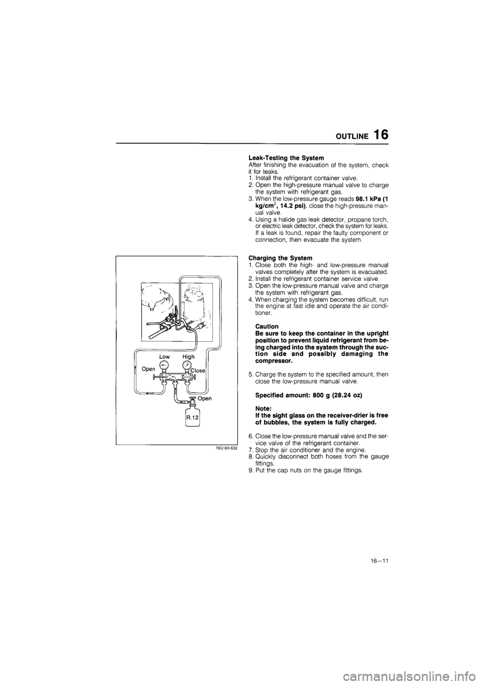
Leak-Testing the System
After finishing the evacuation of the system, check
it for leaks.
1. Install the refrigerant container valve.
2. Open the high-pressure manual valve to charge
the system with refrigerant gas.
3. When the low-pressure gauge reads 98.1 kPa (1
kg/cm2, 14.2 psi), close the high-pressure man-
ual valve.
4. Using a halide gas leak detector, propane torch,
or electric leak detector, check the system for leaks.
If a leak is found, repair the faulty component or
connection, then evacuate the system.
76G16X-632
Charging the System
1. Close both the high- and low-pressure manual
valves completely after the system is evacuated.
2. Install the refrigerant container service valve.
3. Open the low-pressure manual valve and charge
the system with refrigerant gas.
4. When charging the system becomes difficult, run
the engine at fast idle and operate the air condi-
tioner.
Caution
Be sure to keep the container in the upright
position to prevent liquid refrigerant from be-
ing charged into the system through the suc-
tion side and possibly damaging the
compressor.
5. Charge the system to the specified amount, then
close the low-pressure manual valve.
Specified amount: 800 g (28.24 oz)
Note:
If the sight glass on the receiver-drier is free
of bubbles, the system is fully charged.
6. Close the low-pressure manual valve and the ser-
vice valve of the refrigerant container.
7. Stop the air conditioner and the engine.
8. Quickly disconnect both hoses from the gauge
fittings.
9. Put the cap nuts on the gauge fittings.
16—11
Page 1796 of 1865
COMPRESSOR 16
69G16X-026
M10X1.25^45
Low-pressure x pressure
hose hose Compressor
COMPRESSOR
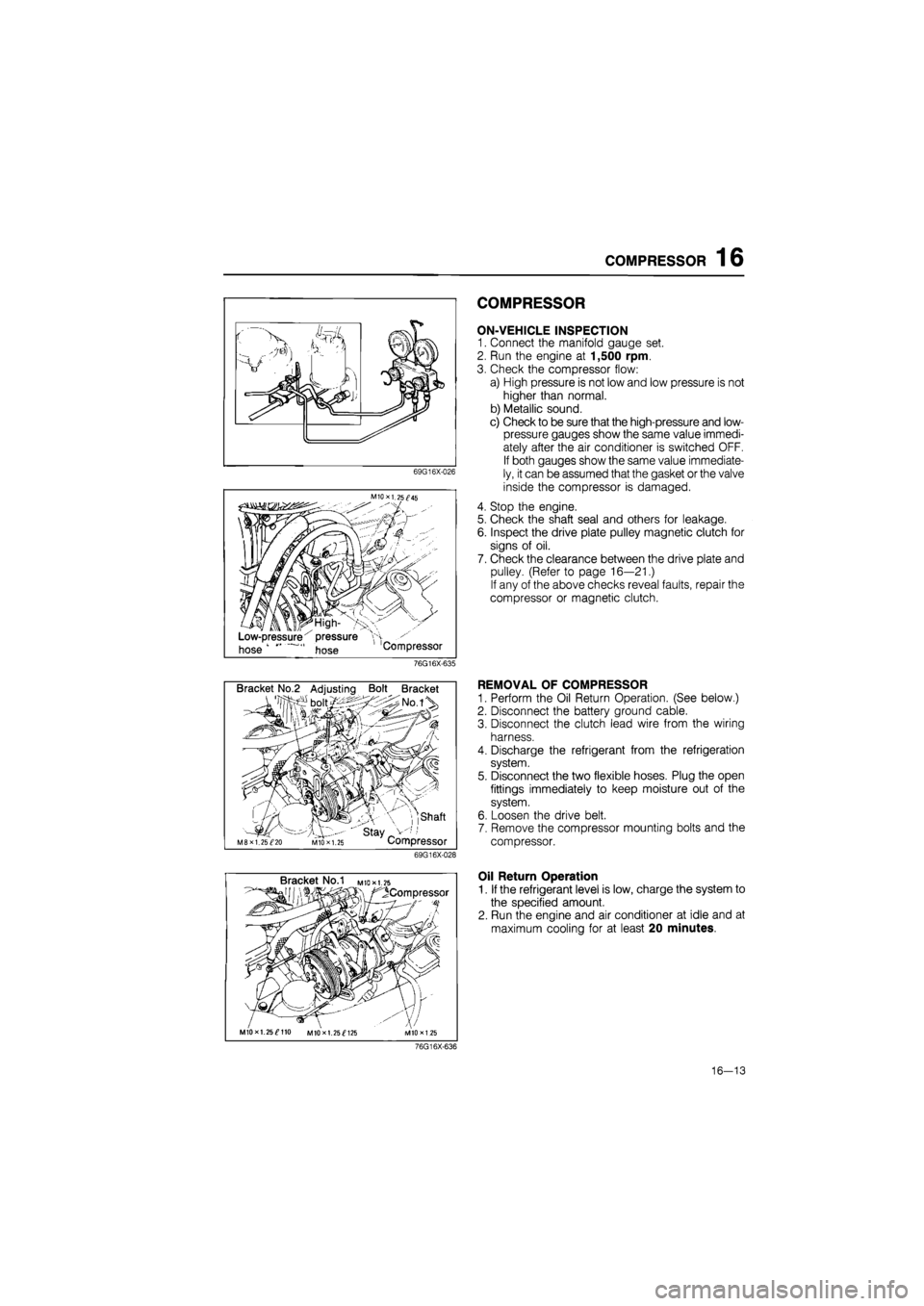
ON-VEHICLE INSPECTION
1. Connect the manifold gauge set.
2. Run the engine at 1,500 rpm.
3. Check the compressor flow:
a) High pressure is not low and low pressure is not
higher than normal.
b) Metallic sound.
c) Check to be sure that the high-pressure and low-
pressure gauges show the same value immedi-
ately after the air conditioner is switched OFF.
If both gauges show the same value immediate-
ly, it can be assumed that the gasket or the valve
inside the compressor is damaged.
4. Stop the engine.
5. Check the shaft seal and others for leakage.
6. Inspect the drive plate pulley magnetic clutch for
signs of oil.
7. Check the clearance between the drive plate and
pulley. (Refer to page 16—21.)
If any of the above checks reveal faults, repair the
compressor or magnetic clutch.
76G16X-635
Bracket No.2 Adjusting Bolt Bracket
, ,shaft
' stay _ M8XI. 25^20 MIO X 1.25 Compressor
69G16X-028
REMOVAL OF COMPRESSOR
1. Perform the Oil Return Operation. (See below.)
2. Disconnect the battery ground cable.
3. Disconnect the clutch lead wire from the wiring
harness.
4. Discharge the refrigerant from the refrigeration
system.
5. Disconnect the two flexible hoses. Plug the open
fittings immediately to keep moisture out of the
system.
6. Loosen the drive belt.
7. Remove the compressor mounting bolts and the
compressor.
Bracket No.1 M
to* 1.25
^Compressor
MIOxl. 25^110 MIOxl. 25^125
Oil Return Operation
1. If the refrigerant level is low, charge the system to
the specified amount.
2. Run the engine and air conditioner at idle and at
maximum cooling for at least 20 minutes.
76G16X-636
16—13
Page 1808 of 1865
RECEIVER-DRIER 16
RECEIVER-DRIER
ON-VEHICLE INSPECTION
1. Use a leak detector to check the sight glass, the
fusible plug, and the fittings for leakage.
Repair or replace, if necessary.
2. Check the receiver-drier for clogging.
a) Run the engine at fast idle with the air conditioner
on.
b) Check both inlet and outlet temperatures.
If there is a great difference between the two tem-
peratures, replace the receiver-drier.
76G16X-622
Receiver-drier
Condenser bolt
76G16X-638
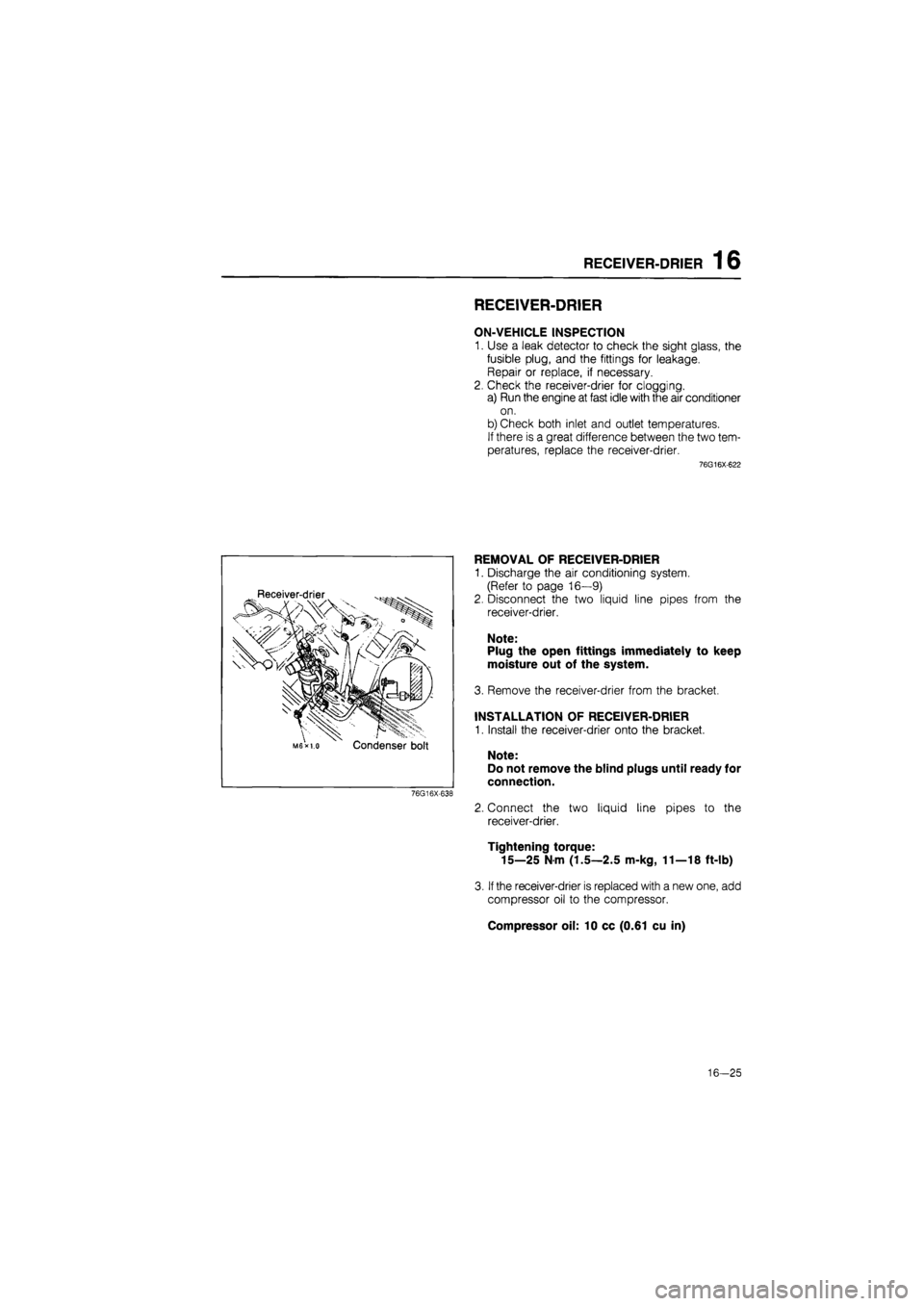
REMOVAL OF RECEIVER-DRIER
1. Discharge the air conditioning system.
(Refer to page 16—9)
2. Disconnect the two liquid line pipes from the
receiver-drier.
Note:
Plug the open fittings immediately to keep
moisture out of the system.
3. Remove the receiver-drier from the bracket.
INSTALLATION OF RECEIVER-DRIER
1. Install the receiver-drier onto the bracket.
Note:
Do not remove the blind plugs until ready for
connection.
2. Connect the two liquid line pipes to the
receiver-drier.
Tightening torque:
15—25 N m (1.5—2.5 m-kg, 11—18 ft-lb)
3.
If
the receiver-drier is replaced with a new one, add
compressor oil to the compressor.
Compressor oil: 10 cc (0.61 cu in)
16-25
Page 1809 of 1865
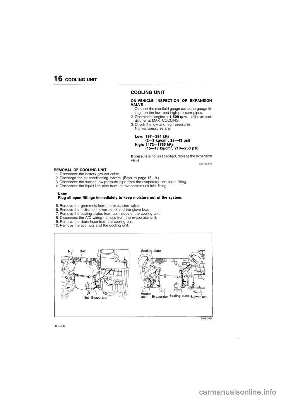
16 COOLING UNIT
COOLING UNIT
ON-VEHICLE INSPECTION OF EXPANSION
VALVE
1. Connect the manifold gauge set to the gauge fit-
tings on the low- and high-pressure pipes.
2. Operate the engine at 1,500 rpm and the air con-
ditioner at MAX. COOLING.
3. Check the low and high pressures.
Normal pressures are:
Low: 197—294 kPa
(2—3 kg/cm2, 28—43 psi)
High: 1472—1765 kPa
(15—18 kg/cm2, 210—260 psi)
If pressure is not as specified, replace the expansion
valve.
76G16X-623
REMOVAL OF COOLING UNIT
1. Disconnect the battery ground cable.
2. Discharge the air conditioning system. (Refer to page 16—9.)
3. Disconnect the suction low-pressure pipe from the evaporator unit outlet fitting.
4. Disconnect the liquid line pipe from the evaporator unit inlet fitting.
Note:
Plug all open fittings immediately to keep moisture out of the system.
5. Remove the grommets from the expansion valve.
6. Remove the instrument lower panel and the glove box.
7. Remove the sealing plates from both sides of the cooling unit.
8. Disconnect the A/C wiring harness from the evaporator unit.
9. Remove the drain hose from the cooling unit.
10. Remove the two nuts and the cooling unit.
76G16X-624
16-26
Page 1831 of 1865
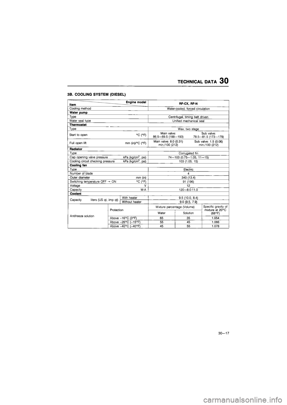
TECHNICAL DATA 30
3B. COOLING SYSTEM (DIESEL)
Item Engine model RF-CX, RF-N
Cooling method Water-cooled, forced circulation
Water pump
Type Centrifugal, timing belt driven
Water seal type Unified mechanical seal
Thermostat
Type Wax, two stage
Start
to
open °C (°F) Main valve:
86.5-89.5 (188-193)
78.5-
Sub valve: 81.5 (173-179)
Full open lift mm (in)/°C (°F) Main valve: 8.0 (0.31) Sub valve: 1.5 (0.06) min./100 (212) min./100 (212)
Radiator
Type Corrugated
fin
Cap opening valve pressure kPa (kg/cm2,
psi)
74—103 (0.75—1.05,
11
-15)
Cooling circuit checking pressure kPa (kg/cm2,
psi)
103 (1.05,
15)
Cooling fan
Type Electric
Number
of
blade 4
Outer diameter mm (in) 340 (13.4)
Switching temperature OFF -»
ON
°C (°F) 91 (196)
Voltage V 12
Capacity W-A 120-8.0-11.0
Coolant
Capacity liters (US qt, Imp
qt)
With heater 9.5 (10.0, 8.4) Capacity liters (US qt, Imp
qt)
Without heater 9.0 (9.5, 7.9)
Protection Mixture percentage (Volume) Specific gravity
of
mixture
at
20°C (68 °F) Antifreeze solution
Protection Water Solution
Specific gravity
of
mixture
at
20°C (68 °F) Antifreeze solution Above -16°C (3°F) 65 35 1.054
Above -26°C (-15°F) 55 45 1.066
Above -40°C (-40°F) 45 55 1.078
30-17
Page 1845 of 1865
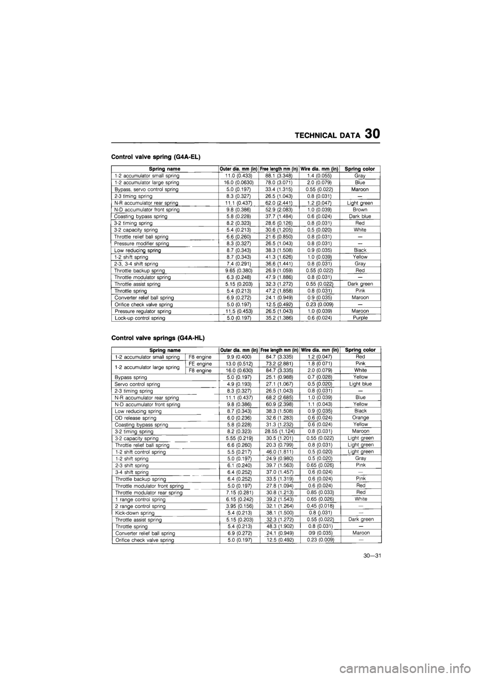
TECHNICAL DATA 30
Control valve spring (G4A-EL)
Spring name Outer dia. mm (in) Free length mm (in) Wire dia. mm (in) Spring color
1-2 accumulator small spring 11.0 (0.433) 88.1 (3.348) 1.4 (0.055) Gray
1-2 accumulator large spring 16.0 (0.0630) 78.0 (3.071) 2.0 (0.079) Blue
Bypass, servo control spring 5.0 (0.197) 33.4 (1.315) 0.55 (0.022) Maroon
2-3 timing spring 8.3 (0.327) 26.5 (1.043) 0.8 (0.031)
—
N-R accumulator rear spring 11.1 (0.437) 62.0 (2.441) 1.2 (0.047) Light green
N-D accumulator front spring 9.8 (0.386) 52.9 (2.083) 1.0 (0.039) Brown
Coasting bypass spring 5.8 (0.228) 37.7 (1.484) 0.6 (0.024) Dark blue
3-2 timing spring 8.2 (0.323) 28.6 (0.126) 0.8 (0.031) Red
3-2 capacity spring 5.4 (0.213) 30.6 (1.205) 0.5 (0.020) White
Throttle relief ball spring 6.6 (0.260) 21.6 (0.850) 0.8 (0.031)
—
Pressure modifier spring 8.3 (0.327) 26.5 (1.043) 0.8 (0.031)
—
Low reducing spring 8.7 (0.343) 38.3 (1.508) 0.9 (0.035) Black
1-2 shift spring 8.7 (0.343) 41.3 (1.626) 1.0 (0.039) Yellow
2-3, 3-4 shift spring 7.4 (0.291) 36.6 (1.441) 0.8 (0.031) Gray
Throttle backup spring 9.65 (0.380) 26.9 (1.059) 0.55 (0.022) Red
Throttle modulator spring 6.3 (0.248) 47.9 (1.886) 0.8 (0.031)
—
Throttle assist spring 5.15 (0.203) 32.3 (1.272) 0.55 (0.022) Dark green
Throttle spring 5.4 (0.213) 47.2 (1.858) 0.8 (0.031) Pink
Converter relief ball spring 6.9 (0.272) 24.1 (0.949) 0.9 (0.035) Maroon
Orifice check valve spring 5.0 (0.197) 12.5 (0.492) 0.23 (0.009)
—
Pressure regulator spring 11.5 (0.453) 26.5 (1.043) 1.0 (0.039) Maroon
Lock-up control spring 5.0 (0.197) 35.2 (1.386) 0.6 (0.024) Purple
Control valve springs (G4A-HL)
SDrina name Outer dia. mm (in) Free length mm (in) Wire dia. mm (in) Spring color
1-2 accumulator small spring F8 enaine 9.9 (0.400) 84.7 (3.335) 1.2 (0.047) Red
1-2 accumulator large spring FE engine 13.0 (0.512) 73.2 (2.881) 1.8 (0 071) Pink 1-2 accumulator large spring F8 enaine 16.0 (0.630) 84.7 (3.335) 2.0 (0.079) White
Bypass spring 5.0 (0.197) 25.1 (0.988) 0.7 (0.028) Yellow
Servo control sorina 4.9 (0.193) 27.1 (1.067) 0.5 (0.020) Light blue
2-3 timing soring 8.3 (0.327) 26.5 (1.043) 0.8 (0.031)
—
N-R
accumulator rear SDrina
11.1 (0.437) 68.2 (2.685) 1.0 (0.039) Blue
N-D accumulator front spring 9.8 (0.386) 60.9 (2.398) 1.1 (0.043) Yellow
Low reducing spring 8.7 (0.343) 38.3 (1.508) 0.9 (0.035) Black
OD release spring 6.0 (0.236) 32.6 (1.283) 0.6 (0.024) Orange
Coasting bypass spring 5.8 (0.228) 31.3 (1.232) 0.6 (0.024) Yellow
3-2 timing soring 8.2 (0.323) 28.55 (1.124) 0.8 (0.031) Maroon
3-2 capacity spring 5.55 (0.219) 30.5 (1.201) 0.55 (0.022) Light green
Throttle relief ball soring 6.6 (0.260) 20.3 (0.799) 0.8 (0.031) Light green
1-2 shift control spring 5.5 (0.217) 46.0 (1.811) 0.5 (0.020) Liaht oreen
1-2 shift soring 5.0 (0.197) 24.9 (0.980) 0.5 (0.020) Gray
2-3 shift soring 6.1 (0.240) 39.7 (1.563) 0.65 (0.026) Pink
3-4 shift spring 6.4 (0.252) 37.0 (1.457) 0.6 (0.024)
—
Throttle backup spring 6.4 (0.252) 33.5 (1.319) 0.6 (0.024) Pink
Throttle modulator front spring 5.0 (0.197) 27.8 (1.094) 0.6 (0.024) Red
Throttle modulator rear spring 7.15 (0.281) 30.8 (1.213) 0.85 (0.033) Red
1
ranoe control SDrina
6.15 (0.242) 39.2 (1.543) 0.65 (0.026) White
2 range control spring 3.95 (0.156) 32.1 (1.264) 0.45 (0.018)
—
Kick-down
SDrina
5.4 (0.213) 38.1 (1.500) 0.8 0.031)
—
Throttle assist spring 5.15 (0.203) 32.3 (1.272) 0.55 (0.022) Dark green
Throttle spring 5.4 (0.213) 48.3 (1.902) 0.8 (0.031)
—
Converter relief ball spring 6.9 (0.272) 24.1 (0.949) 0I9 (0.035) Maroon
Orifice check valve soring 5.0 (0.197) 12.5 (0.492) 0.23 (0.009)
—
30—31
Page 1848 of 1865
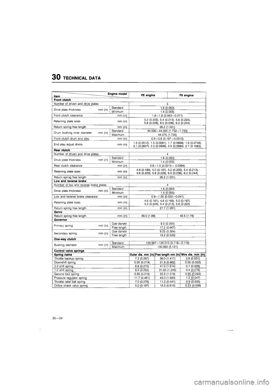
30 TECHNICAL DATA
Item Engine model FE engine F6 engine
Front clutch
Number
of
driven and drive plates 3
Drive plate thickness mm (in) Standard 1.6 (0.063) Drive plate thickness mm (in) Minimum 1.4 (0.055)
Front clutch clearance mm (in) 1.6-1.8 (0.063-0.071)
Retaining plate sizes mm (in) 5.2 (0.205), 5.4 (0.213), 5.6 (0.220),
5.8 (0.228), 6.0 (0.236), 6.2 (0.244)
Return spring free length mm (in) 26.2 (1.031)
Drum bushing inner diameter mm (in) Standard 44.000-44.025 (1.732-1.733) Drum bushing inner diameter mm (in) Maximum 44.075 (1.735)
Front clutch drum end play mm (in) 0.5-0.8 (0.197-0.0315)
End play adjust shims mm (in) 1.3 (0.0512), 1.5 (0.0591), 1.7 (0.0669), 1.9 (0.0748), 2.1 (0.0827), 2.3 (0.0906),
2.5
(0.0984), 2.7 (0.1063)
Rear clutch
Number
of
driven and drive plates 4
Drive plate thickness mm (in) Standard 1.6 (0.063) Drive plate thickness mm (in) Minimum 1.4 (0.055)
Rear clutch clearance mm (in) 0.8--1.0 (0.0315- 0.0394)
Retaining plate sizes mm (in) 4.8 (0.189), 5.0 (0.197), 5.2 (0.205), 5.4 (0.213),
5.6 (0.220), 5.8 (0.228), 6.0 (0.236), 6.2 (0.244)
Return spring free length mm (in) 26.2 (1.031)
Low and reverse brake
Number
of
low and reverse brake plates 4
Drive plate thickness mm (in) Standard 1.6 (0.063) Drive plate thickness mm (in) Minimum 1.4 (0.055)
Low and reverse brake clearance mm (in) 0.8-1.05 (0.032-0.041)
Retaining plate sizes mm (in) 4.6 (0.181),
4.8
(0.189), 5.0 (0.197), 5.2 (0.205), 5.4 (0.213), 5.6 (0.220)
Return spring free length mm (in) 27.7 (1.091)
Servo
Return sprina free lenath mm (in) 48.0 (1.89) 45.5 (1.79)
Governor
Primary spring mm (in) Outer diameter 9.0 (0.354) Primary spring mm (in) Free lenath 17.2 (0.667)
Secondary spring mm (in) Outer diameter 9.25 (0.364) Secondary spring mm (in) Free lenath 13.2 (0.520)
One-wav clutch
Bushing diameter mm (in) Standard 129.987-130.013 (5.118--5.119) Bushing diameter mm (in) Maximum 130.063 (5.121)
Control valve SDrinas
Spring name Outer dia. mm (in) Free length mm (in) Wire dia. mm (in)
Throttle backup spring 7.3 (0.287) 36.0 (1.417) 0.8 (0.031)
Downshift sorina 5.55 (0.219) 21.9 (0.862) 0.55 (0.022)
2-3 shift spring 6.9 (0.272) 41.0 (1.614) 0.7 (0.028)
1-2 shift spring 6.4 (0.252) 31.63 (1.245) 0.4 (0.016)
Second lock spring 5.55 (0.219) 33.5 (1.319) 0.55 (0.022)
Pressure reaulator sprina 11.7 (0.461) 43.0 (1.693) 1.2 (0.047)
Throttle relief ball spring 7.0 (0.276) 11.2 (0.441) 0.9 (0.035)
Orifice check valve sprina 5.0 (0.197) 15.5 (0.610) 0.23 (0.009)
30-34
Page 1855 of 1865
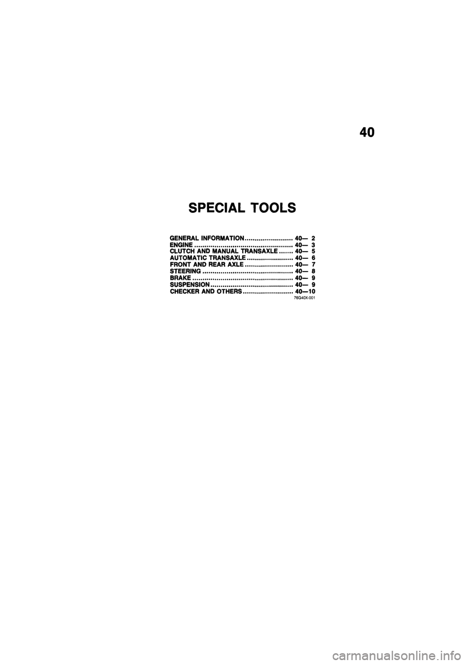
40
SPECIAL TOOLS
GENERAL INFORMATION 40— 2
ENGINE 40- 3
CLUTCH AND MANUAL TRANSAXLE 40- 5
AUTOMATIC TRANSAXLE 40— 6
FRONT AND REAR AXLE 40— 7
STEERING 40— 8
BRAKE 40— 9
SUSPENSION 40— 9
CHECKER AND OTHERS 40—10 76G40X-001
Page 1864 of 1865
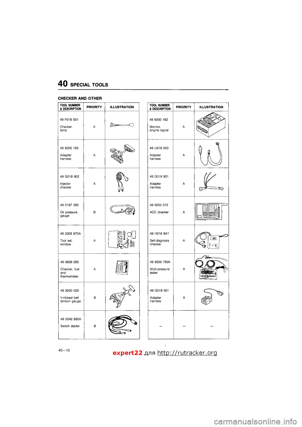
40 SPECIAL TOOLS
CHECKER AND OTHER
TOOL NUMBER & DESCRIPTION
49 F018 001
Checker lamp
49 9200
163
Adapter
harness
49 G018 902
Injector
checker
49 0187 280
Oil pressure gauge
49 0305 870A
Tool set,
window
49 0839 285
Checker, fuel
and
thermometer
49 9200
020
V-ribbed belt tension gauge
49 0242 685A
Switch starter
PRIORITY ILLUSTRATION TOOL NUMBER & DESCRIPTION
49 9200
162
Monitor, engine signal
49 U018 003
Adapter harness
49 G018 901
Adapter
harness
49 9200 010
ACC checker
49 H018 9A1
Self-diagnosis
checker
49 9200 750A
Multi-pressure
tester
49 G018 001
Adapter harness
PRIORITY ILLUSTRATION
40—10 expert22 /yia http://rutracker.org