tow MAZDA 626 1987 Owner's Guide
[x] Cancel search | Manufacturer: MAZDA, Model Year: 1987, Model line: 626, Model: MAZDA 626 1987Pages: 1865, PDF Size: 94.35 MB
Page 1634 of 1865

SLIDING SUNROOF 14
76U14X-047
Sun shade ^^Sun shade^,stopper
\ )j
/L.
^/''^//l J ' //r- OOf^/l
76U14X-048
76U14X-049
Connector
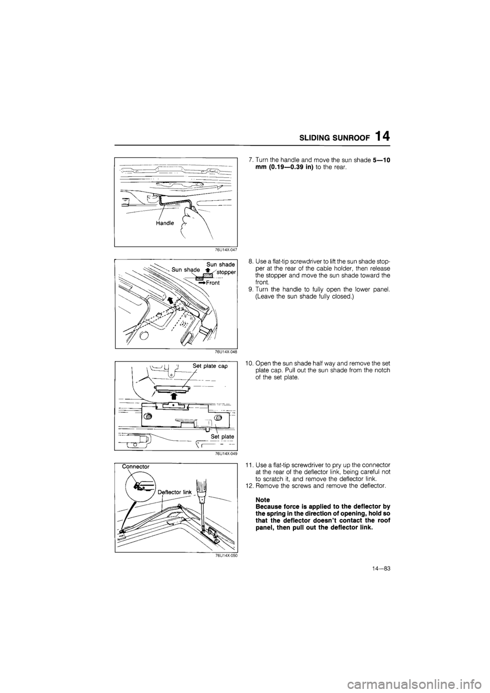
7. Turn the handle and move the sun shade 5—10
mm (0.19—0.39 in) to the rear.
8. Use a flat-tip screwdriver to lift the sun shade stop-
per at the rear of the cable holder, then release
the stopper and move the sun shade toward the
front.
9. Turn the handle to fully open the lower panel.
(Leave the sun shade fully closed.)
10. Open the sun shade half way and remove the set
plate cap. Pull out the sun shade from the notch
of the set plate.
11. Use a flat-tip screwdriver to pry up the connector
at the rear of the deflector link, being careful not
to scratch it, and remove the deflector link.
12. Remove the screws and remove the deflector.
Note
Because force is applied to the deflector by
the spring in the direction of opening, hold so
that the deflector doesn't contact the roof
panel, then pull out the deflector link.
76U14X-050
14—83
Page 1637 of 1865

1 4 SLIDING SUNROOF
3. After moving the guide bracket assembly slightly
toward the rear, tighten the screw, taking care
regarding the direction the set plate faces.
76U14X-059
Ipi
" (E) ling
Notch jilting Cam
—+ * ) siii
Align the projection of the tilting cam and the slit
in the set plate.
76U14X-060
5. Check that the limit switches (LS1 and LS2) of the
motor are as shown in the figure at the OFF po-
sition.
Note
a) Be careful of the cam position.
b) Use the handle to position it correctly.
76U14X-061
6. Install the motor assembly.
Note
There are 2 types of screws, long and short.
Be sure to use the correct ones.
7. Connect the wiring of the motor assembly and the
motor switch.
76U14X-062
14-86
Page 1792 of 1865

OUTLINE 16
Discharging the Refrigeration System
1. Connect the manifold gauge set to the system.
2. Place the free end of the center hose on a shop
towel.
3. Slowly open the high pressure manual valve to ad-
just the refrigerant flow. Open the valve only slightly.
Caution
If refrigerant is allowed to escape too fast, the
compressor oil will be drawn out of the
system.
4. Check the shop towel to make sure no oil is being
discharged.
If oil is present, partially close the manual valve.
5. After the manifold gauge reading drops below 343
kPa (3.5 kg/cm2, 50 psi), slowly open the low
pressure manual valve.
6. As the system pressure drops, gradually open both
the high- and low-pressure manual valves until both
gauges read 0 kPa (0 kg/cm2, 0 psi).
76G16X-631
Evacuation of the Refrigeration System
Whenever the air-conditioning system has been ex-
posed to the atmosphere, it must be evacuated.
1. Connect the manifold gauge set.
2. Connect the center hose of the gauge set to the
vacuum pump inlet.
3. Operate the vacuum pump, then open both man-
ual valves.
4. When the low pressure gauge indicates approxi-
mately 710 mmHg (28 inHg), close both manual
valves and stop the vacuum pump.
5. Check to be sure that the degree of pressure does
not change after 10 minutes or more in this condi-
tion.
If
the pressure changes, check the system for
leaks, and repair if necessary.
6. If no leaks are found, once again operate the vacu-
um pump and open both manual valves to obtain
760 mmHg (30 inHg).
7. Close both manual valves, and stop the vacuum
pump.
Disconnect the hose from the vacuum pump.
69G16X-019
16-9