tow MAZDA 626 1987 User Guide
[x] Cancel search | Manufacturer: MAZDA, Model Year: 1987, Model line: 626, Model: MAZDA 626 1987Pages: 1865, PDF Size: 94.35 MB
Page 804 of 1865

6 CLUTCH AND FLYWHEEL
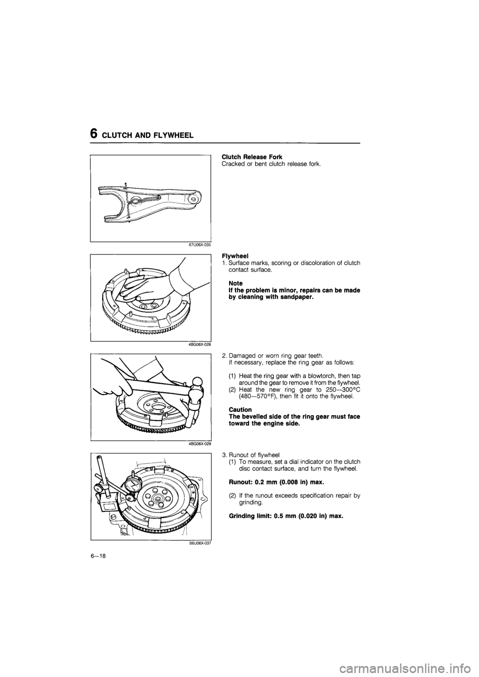
Clutch Release Fork
Cracked or bent clutch release fork.
67U06X-035
4BG06X-028
4BG06X-029
Flywheel
1. Surface marks, scoring or discoloration of clutch
contact surface.
Note
If the problem is minor, repairs can be made
by cleaning with sandpaper.
2. Damaged or worn ring gear teeth.
If necessary, replace the ring gear as follows:
(1) Heat the ring gear with a blowtorch, then tap
around the gear to remove
it
from the flywheel.
(2) Heat the new ring gear to 250—300°C
(480—570°F), then fit it onto the flywheel.
Caution
The bevelled side of the ring gear must face
toward the engine side.
3. Runout of flywheel
(1) To measure, set a dial indicator on the clutch
disc contact surface, and turn the flywheel.
Runout: 0.2 mm (0.008 in) max.
(2) If the runout exceeds specification repair by
grinding.
Grinding limit: 0.5 mm (0.020 in) max.
86U06X-037
6-18
Page 823 of 1865

REMOVAL 7A
26. Remove the engine mount No. 4 and bracket.
86U07A-031
86U07A-032
86U07A-033
27. Remove the engine mount No. 2.
28. Disconnect the hanger rubber then remove the
crossmember and the left side lower arm as an as-
sembly.
29. Lean the engine toward the transaxle.
30. Support the transaxle with a jack.
31. Remove the remaining transaxle mounting bolts.
32. Remove the transaxle.
86U07A-034
7 A—17
Page 939 of 1865

ON-VEHICLE MAINTENANCE 7B
76F07B-024
5. Turn locknut A by hand until it just touches the
spacer.
6. Tighten locknut B to the specified torque.
Tightening torque:
8—11 N m (80—110 cm-kg, 67—96 in-lb)
7. Shift the selector lever to N range.
8. With the button on the selector lever knob pressed,
push the selector toward R range with a force of
20 N (2 kg, 4.4 lb) and check the amount of move-
ment (a) at the selector lever knob.
9. Pull the selector lever toward D range in the same
manner and check the amount of movement (b).
10. Verify the stroke difference of (a) and (b) is as
specified.
Stroke difference: 8 mm (0.315 in) max.
Note
If not with in specification, readjust locknuts
A and B.
11. Check the selector lever operation.
(Refer to Inspection section.)
76F07B-025
THROTTLE CABLE
Inspection
1. Check the inner and outer cable for damage.
2. Make sure that the accelerator operates smoothly.
86U07B-066
Removal
1. Remove the battery and battery carrier.
2. Disconnect the main fuse block. (G4A-EL)
76G07B-090
7B—73
Page 953 of 1865

REMOVAL 7B
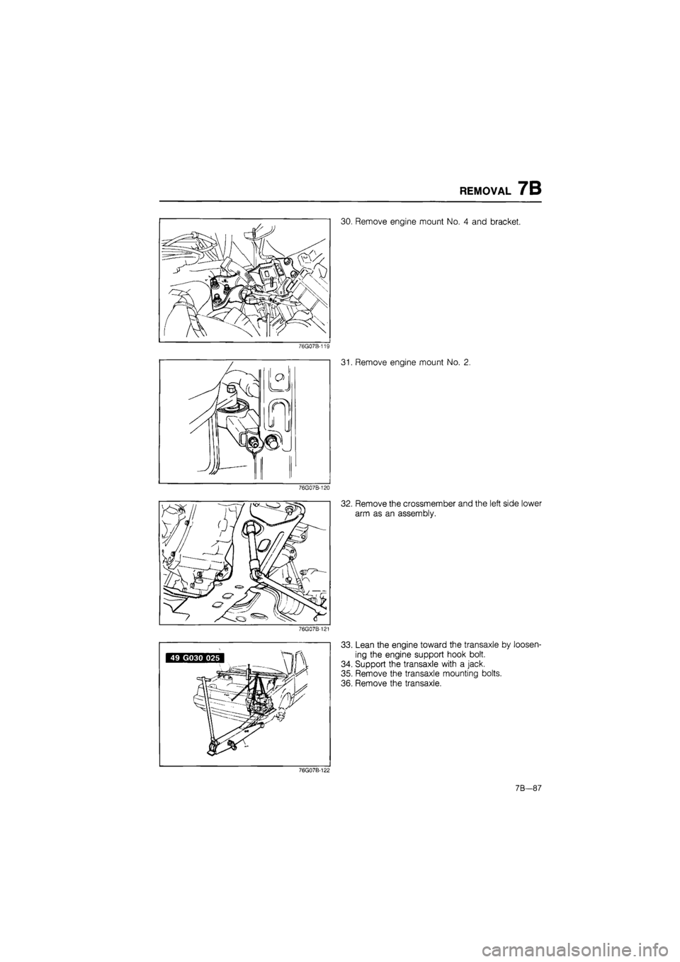
30. Remove engine mount No. 4 and bracket.
76G07B-119
76G07B-120
76G07B-121
31. Remove engine mount No. 2.
32. Remove the crossmember and the left side lower
arm as an assembly.
33. Lean the engine toward the transaxle by loosen-
ing the engine support hook bolt.
34. Support the transaxle with a jack.
35. Remove the transaxle mounting bolts.
36. Remove the transaxle.
76G07B-122
7B—87
Page 977 of 1865

INSPECTION AND REPAIR 7B
Guid spring
86U07B-182
86U07B-183
86U07B-184
6. Install the guide spring and guide ring while ex-
panding the vanes toward the cam ring.
7. Install the pump flange onto the rotor.
8. Install the spring between the cam ring and oil
pump body.
9. Install the seal pins and springs with the pins fac-
ing toward the oil pump body.
Note
Install the seal pins round end first.
10. Install the O-rings.
86U07B-185
7R
1 11
Page 982 of 1865

7B INSPECTION AND REPAIR
6. Spring and retainer assembly for separation or
deformation
Free length of spring:
29.8 mm (1.173 in)
86U07B-198
Assembly
Reverse clutch
1. Install the reverse piston.
(1) Apply ATF to inner and outer faces of the seals,
and install them to the reverse piston.
(2) Face the outer seal lip toward the inside by
gently rolling
it
down around the circumference
for easier installation into the reverse clutch
drum.
86U07B-199
(3) Install the reverse piston by pushing evenly
around the circumference, being careful not to
damage the seal rings.
86U07B-200
2. Install the piston return spring with the tabs facing
away from the reverse piston.
3. Install the return spring stopper with the step fac-
ing upwards.
86U07B-201
7B—116
Page 984 of 1865

7B INSPECTION AND REPAIR
86U07B-206
86U07B-207
86U07B-208
Coasting clutch
1. Install the coasting clutch drum.
(1) Apply ATF to inner and outer faces of the seal,
and install it onto the coasting clutch drum.
(2) Face the outer seal lip toward the inside by
gently rolling it down around the circumference
for easier installation into the drum.
(3) Install the coasting clutch drum the correct po-
sition in the reverse and forward drum.
(4) Push evenly around the circumference, being
careful not to damage the outer seal.
2. Install the coasting piston
(1) Apply ATF to inner and outer faces of the seals
and install them onto the coasting piston.
(2) Face the outer seal lip toward the inside by
gently rolling it down around the circumference
for easier installation into the drum.
(3) Install the coasting piston by pushing evenly
around the circumference, being careful not to
damage the outer seal.
B6U07B-209
7B-118
Page 989 of 1865

INSPECTION AND REPAIR 7B
86U07B-224
86U07B-225
86U07B-226
Replacement of one-way clutch
1. Remove the one-way clutch inner race.
2. Remove the one-way clutch.
3. Remove the thrust bearing.
4. Inspect the one-way clutch inner and outer race,
and replace if necessary.
5. Apply petroleum jelly to the thrust bearing to se-
cure it; then install it to the one-way clutch inner
race.
Thrust bearing outer diameter:
62.1 mm (2.44 in)
6. Install the one-way clutch into the one-way clutch
outer race.
Caution
Check that the spring cage of the one-way
clutch faces toward the outer race.
86U07B-227
7B-123
Page 1066 of 1865

7B ASSEMBLY
(4) Install the detent ball, spring, washer and plug;
then tighten the plug.
Tightening torque:
12—18
N
m (1.2—1.8 m-kg, 8.7—13 ft-lb)
86U07B-386
Install the low and reverse brake piston.
(1) Apply ATF to the inner and outer seals, and
install them to the low and reverse brake piston.
(2) Face the outer seal lip toward the inside by
gently rolling it down around the circumference
for easier installation into the case.
(3) Install the low and reverse brake piston by
pushing evenly around the circumference, be-
ing careful not to damage the outer seal.
86U07B-388
(4) Install the spring and retainer assembly.
86U07B-389
7B-200
Page 1148 of 1865

7C REMOVAL
27. Remove engine mount No. 2.
76G07C-069
76G07C-070
28. Remove the crossmember and the left side lower
arm as an assembly.
29. Lean the engine toward the transaxle by loosen-
ing the engine support hook bolt.
30. Support the transaxle with a jack.
31. Remove the transaxle mounting bolts.
32. Remove the transaxle.
76G07C-071
7C-34