ECO mode MAZDA 626 1987 Workshop Manual
[x] Cancel search | Manufacturer: MAZDA, Model Year: 1987, Model line: 626, Model: MAZDA 626 1987Pages: 1865, PDF Size: 94.35 MB
Page 24 of 1865
o
r\3
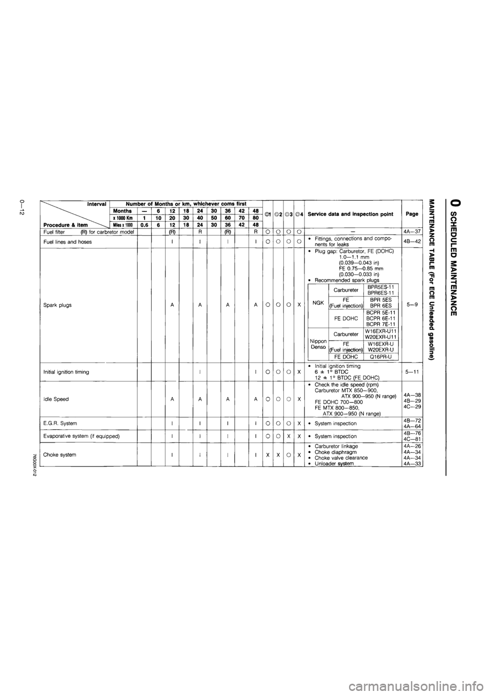
Interval
Procedure & item
Number of Months or km, whichever corns first
Months
x
1000 Km
Miles x 1000
Fuel filter (R) for carbretor model
Fuel lines and hoses
Spark plugs
Initial ignition timing
Idle Speed
E.G.R. System
Evaporative system (if equipped)
O) O
X o
Choke system
0.6
6
10
12
20
12
(R)
18
30
18
24
40
24
30
50
30
36
60
36
(R)
42
70
42
48
80
48
©1
O
O
o
o
o
o
o
o
o
o
o
o
o
o
©3
o
o
o
o
o
o
o
©4
o
o
Service data and inspection point
Fittings, connections and compo-
nents for leaks
Plug gap: Carburetor, FE (DOHC) 1.0—1.1 mm (0.039—0.043 in) FE 0.75—0.85 mm (0.030-0.033 in) Recommended spark plugs
NGK
Carbureter BPR5ES-11 BPR6ES-11
NGK FE
(Fuel injection)
BPR 5ES
BPR 6ES NGK
FE DOHC
BCPR 5E-11 BCPR 6E-11 BCPR 7E-11
Nippon Denso
Carbureter W16EXR-U11 W20EXR-U11 Nippon Denso FE
(Fuel injection)
W16EXR-U
W20EXR-U
Nippon Denso
FE DOHC Q16PR-U
Initial ignition timing
6 ±
1
° BTDC
12 ± 1° BTDC (FE DOHC)
Check the idle speed (rpm) Carburetor MTX 850—900,
ATX 900-950 (N range) FE DOHC 700-800 FE MTX 800—850,
ATX 900-950 (N range)
System inspection
System inspection
Carburetor linkage Choke diaphragm Choke valve clearance Unloader system
Page
4A-37
4B-42
5-9
5-11
4A—38 4B-29 4C—29
4B—72 4A—64
4B—76
4C-81
4A-26 4A—34 4A—34 4A—33
m z >
z o m
H >
00 r-m
H o
m O m
3
CO o X m a c i-m a
m z >
z o m
Page 27 of 1865
For General
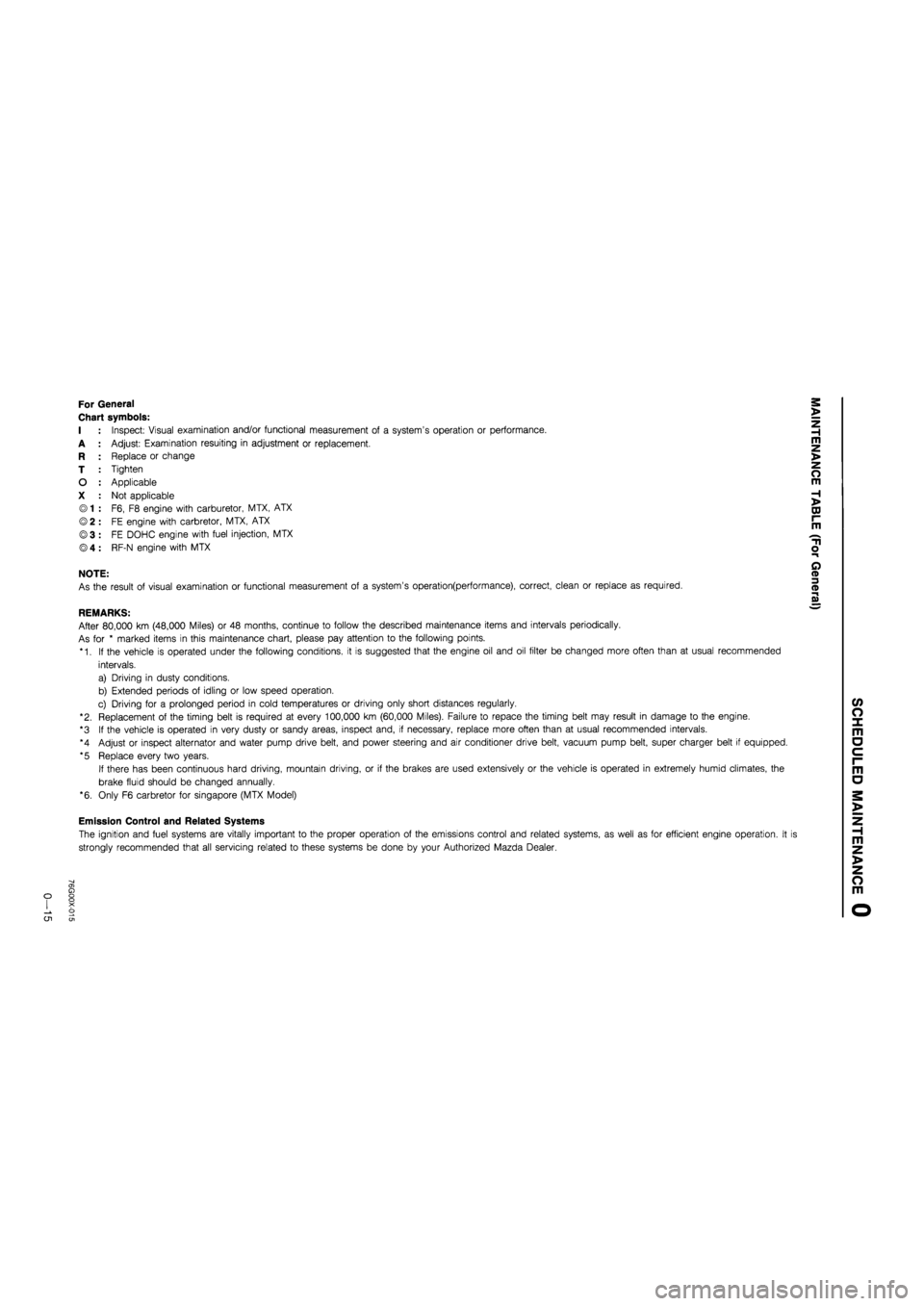
Chart symbols:
I : Inspect: Visual examination and/or functional measurement of a system's operation or performance.
A : Adjust: Examination resuiting in adjustment or replacement.
R : Replace or change
T : Tighten
O : Applicable
X : Not applicable
© 1 : F6, F8 engine with carburetor, MTX, ATX
© 2 : FE engine with carbretor, MTX, ATX
©3 : FE DOHC engine with fuel injection, MTX
® 4 : RF-N engine with MTX
NOTE:
As the result of visual examination or functional measurement of a system's operation(performance), correct, clean or replace as required.
REMARKS:
After 80,000 km (48,000 Miles) or 48 months, continue to follow the described maintenance items and intervals periodically.
As for * marked items in this maintenance chart, please pay attention to the following points.
*1. If the vehicle is operated under the following conditions, it is suggested that the engine oil and oil filter be changed more often than at usual recommended
intervals.
a) Driving in dusty conditions.
b) Extended periods of idling or low speed operation.
c) Driving for a prolonged period in cold temperatures or driving only short distances regularly.
"2. Replacement of the timing belt is required at every 100,000 km (60,000 Miles). Failure to repace the timing belt may result in damage to the engine.
*3 If the vehicle is operated in very dusty or sandy areas, inspect and, if necessary, replace more often than at usual recommended intervals.
*4 Adjust or inspect alternator and water pump drive belt, and power steering and air conditioner drive belt, vacuum pump belt, super charger belt if equipped.
*5 Replace every two years.
If there has been continuous hard driving, mountain driving, or if the brakes are used extensively or the vehicle is operated in extremely humid climates, the
brake fluid should be changed annually.
*6. Only F6 carbretor for Singapore (MTX Model)
Emission Control and Related Systems
The ignition and fuel systems are vitally important to the proper operation of the emissions control and related systems, as well as for efficient engine operation. It i
strongly recommended that all servicing related to these systems be done by your Authorized Mazda Dealer.
o CJ1
Page 315 of 1865
2 A TROUBLESHOOTING GUIDE
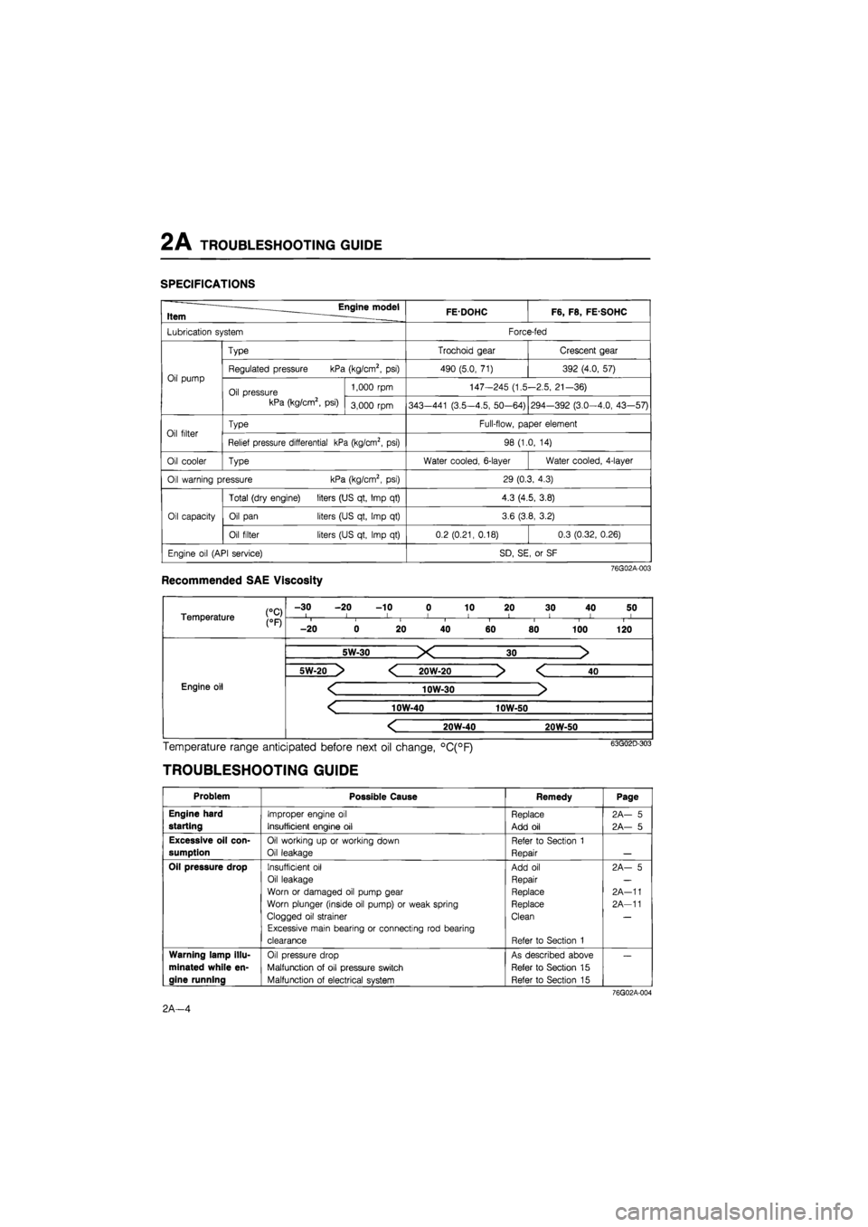
SPECIFICATIONS
Engine model Item . FEDOHC F6, F8, FE SOHC
Lubrication system Force-fed
Oil pump
Type Trochoid gear Crescent gear
Oil pump Regulated pressure kPa (kg/cm2, psi) 490 (5.0, 71) 392 (4.0, 57) Oil pump
Oil pressure kPa (kg/cm2, psi)
1,000 rpm 147-245 (1.5-2.5, 21-36) Oil pump
Oil pressure kPa (kg/cm2, psi) 3,000 rpm 343—441 (3.5-4.5, 50-64) 294-392 (3.0-4.0, 43—57)
Oil filter Type Full-flow, paper element Oil filter Relief pressure differential kPa (kg/cm2, psi) 98 (1.0, 14)
Oil cooler Type Water cooled, 6-layer Water cooled, 4-layer
Oil warning pressure kPa (kg/cm2, psi) 29 (0.3, 4.3)
Oil capacity
Total (dry engine) liters (US qt, Imp qt) 4.3 (4.5, 3.8)
Oil capacity Oil pan liters (US qt, Imp qt) 3.6 (3.8, 3.2) Oil capacity
Oil filter liters (US qt, Imp qt) 0.2 (0.21, 0.18) 0.3 (0.32, 0.26)
Engine oil (API service) SD, SE, or SF
76G02A-003
Recommended SAE Viscosity
Temperature j0pj
-30 -20 -10 0 10 20 30 40 50 I l I I 1 < ! I I Temperature j0pj i i i i I i 1 1
-20 0 20 40 60 80 100 120
Engine oil Engine oil
5W-30 X 30 >
Engine oil Engine oil
5W-20 > < 20W-20 > < 40
Engine oil < 10W-30 > Engine oil
< 10W-40 10W-50
Engine oil Engine oil
< 20W-40 20W-50
Engine oil
Temperature range anticipated before next oil change, °C(°F)
TROUBLESHOOTING GUIDE
Problem Possible Cause Remedy Page
Engine hard
starting
Improper engine oil
Insufficient engine oil
Replace
Add oil
2A— 5
2A— 5
Excessive oil con-
sumption
Oil working up or working down
Oil leakage
Refer to Section 1
Repair
Oil pressure drop Insufficient oil
Oil leakage
Worn or damaged oil pump gear
Worn plunger (inside oil pump) or weak spring
Clogged oil strainer
Excessive main bearing or connecting rod bearing
clearance
Add oil
Repair
Replace
Replace
Clean
Refer to Section 1
2A- 5
2A-11
2A-11
Warning lamp illu-
minated while en-
gine running
Oil pressure drop
Malfunction of oil pressure switch
Malfunction of electrical system
As described above
Refer to Section 15
Refer to Section 15
76G02A-004
2A—4
Page 327 of 1865
OUTLINE 2B
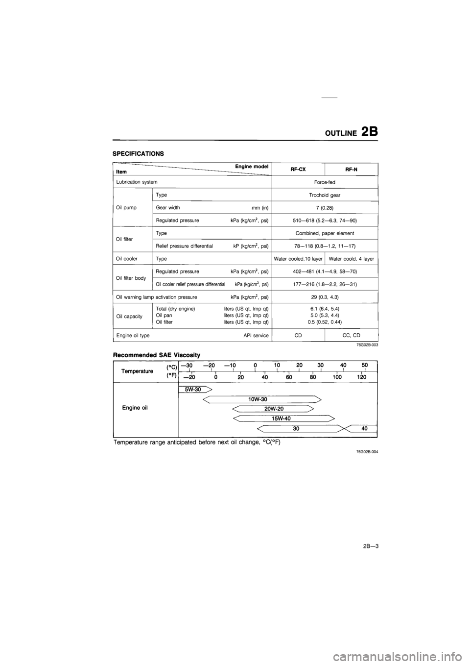
SPECIFICATIONS
Item Engine model RF-CX RF-N
Lubrication system Force-fed
Type Trochoid gear
Oil pump Gear width mm (in) 7 (0.28)
Regulated pressure kPa (kg/cm2,
psi)
510-618 (5.2 -6.3, 74—90)
Oil filter
Type Combined, paper element
Oil filter
Relief pressure differential kP (kg/cm2,
psi)
78-118 (0.8--1.2, 11-17)
Oil cooler Type Water cooled, 10 layer Water coold,
4
layer
Oil filter body
Regulated pressure kPa (kg/cm2,
psi)
402—481
(4.1
-4.9, 58—70)
Oil filter body
Oil cooler relief pressure differential kPa (kg/cm2, psi) 177-216 (1.8 -2.2, 26-31)
Oil warning lamp activation pressure kPa (kg/cm2,
psi)
29 (0.3, 4.3)
Oil capacity
Total (dry engine)
Oil pan
Oil filter
liters (US qt, Imp
qt)
liters (US qt, Imp
qt)
liters (US qt, Imp
qt)
6.1 (6.4, 5.4)
5.0 (5.3, 4.4)
0.5 (0.52, 0.44)
Engine oil type API service CD CC,
CD
76G02B-003
Recommended SAE Viscosity
CC) Temperature
—30 —20 —10 0 10 20 30 40 50 i i i i i i i ii CC) Temperature i i II i i i i —20 0 20 40 60 80 100 120
Engine oil
5W-30 >
Engine oil
< 10W-30 >
< 20W-20 >
< 15W-40 >
Engine oil
Temperature range anticipated before next oil change, °C(°F)
76G02B-004
2B-3
Page 868 of 1865
7B OUTLINE
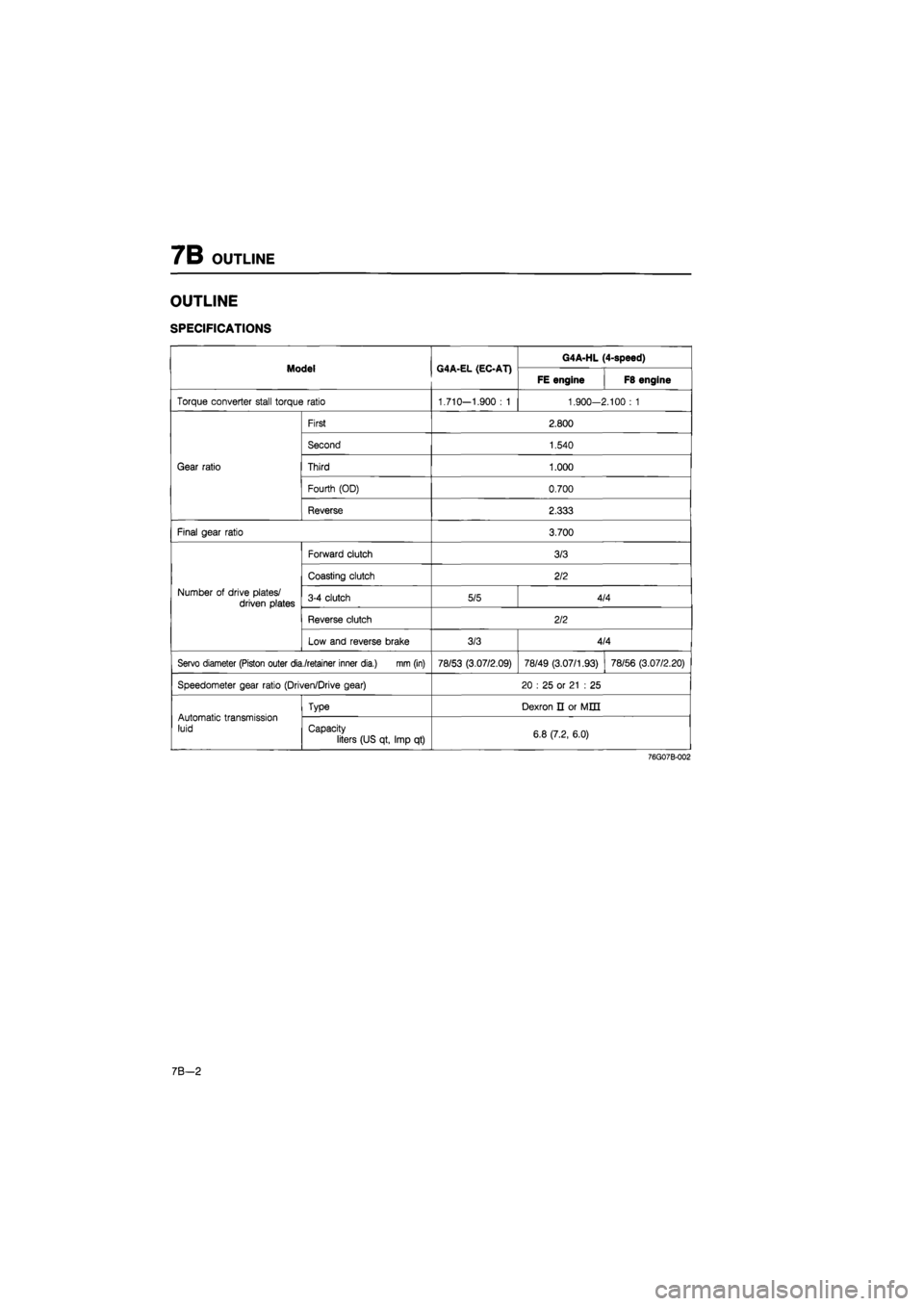
OUTLINE
SPECIFICATIONS
Model G4A-EL (EC-AT) G4A-HL (4-speed) Model G4A-EL (EC-AT)
FE engine F8 engine
Torque converter stall torque ratio 1.710—1.900
: 1
1.900-2.100
: 1
Gear ratio
First 2.800
Gear ratio
Second 1.540
Gear ratio Third 1.000 Gear ratio
Fourth (OD) 0.700
Gear ratio
Reverse 2.333
Final gear ratio 3.700
Number
of
drive plates/ driven plates
Forward clutch 3/3
Number
of
drive plates/ driven plates
Coasting clutch 2/2
Number
of
drive plates/ driven plates 3-4 clutch 5/5 4/4 Number
of
drive plates/ driven plates
Reverse clutch 2/2
Number
of
drive plates/ driven plates
Low and reverse brake 3/3 4/4
Servo diameter (Piston outer dia./retainer inner dia.) mm (in) 78/53 (3.07/2.09) 78/49 (3.07/1.93) 78/56 (3.07/2.20)
Speedometer gear ratio (Driven/Drive gear) 20
: 25 or
21
: 25
Automatic transmission luid
Type Dexron
n or
MED
Automatic transmission luid Capacity
liters (US qt, Imp
qt)
6.8 (7.2, 6.0)
76G07B-002
7 B—2
Page 890 of 1865
7B TROUBLESHOOTING (G4A-EL)
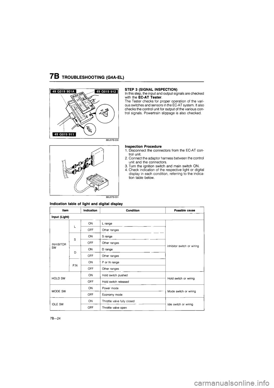
STEP 3 (SIGNAL INSPECTION)
In this step, the input and output signals are checked
with the EC-AT Tester.
The Tester checks for proper operation of the vari-
ous switches and sensors in the EC-AT system. It also
checks the control unit for output of the various con-
trol signals. Powertrain slippage is also checked.
Inspection Procedure
1. Disconnect the connectors from the EC-AT con-
trol unit.
2. Connect the adaptor harness between the control
unit and the connectors.
3. Turn the ignition switch and main switch ON.
4. Check indication of the respective light or digital
display in each condition, referring to the indica-
tion table below.
Indication table of light and digital display
Item Indication Condition Possible cause
Input (Light)
L ON L range L OFF Other ranges
S
ON S range
INHIBITOR
S OFF Other ranges Inhibitor switch or wiring SW
D ON D range
Inhibitor switch or wiring
D
OFF Other ranges
P,N
ON P or N range P,N OFF Other ranges
HOLD SW ON Hold switch pushed Hold switch or wiring HOLD SW
OFF Hold switch released
Hold switch or wiring
MODE SW ON Power mode Mode switch or wiring MODE SW
OFF Economy mode
Mode switch or wiring
IDLE SW ON Throttle valve fully closed Idle switch or wiring IDLE SW
OFF Throttle valve open
Idle switch or wiring
7B-24
Page 891 of 1865

TROUBLESHOOTING (G4A-EL) 7B
Item Indication Condition Possible cause
BRAKE LIGHT SW ON Brake pedal depressed Brake light switch or
wiring BRAKE LIGHT SW
OFF Brake pedal released
Brake light switch or
wiring
WATER TEMP SW ON Coolant temperature 72°C (162°F) or above Water temp switch or wiring WATER TEMP SW
OFF Coolant temperature lower than 65°C (149°F)
Water temp switch or wiring
ATF TEMP SW ON ATF temperature 150°C (302°F) or above Fluid temperature switch or wiring ATF TEMP SW
OFF ATF temperature lower than 143°C (289°F)
Fluid temperature switch or wiring
CRUISE CONTROL SW Not used — —
Input (Digital display)
THROTTLE SENSOR
EC-AT control unit terminal voltage All the time Throttle sensor, idle switch or wirings
VEHICLE SPEED*
Vehicle speed calculated from speed sensor signal
All the time Vehicle speed sensor, speedometer cable, or wiring
DRUM SPEED* Drum speed All the time Pulse generator or wirings
Output (Light)
1-2 SOLENOID VALVE*
ON
Refer to page 7B—26 solenoid valve operation table
Control unit, 1-2 shift sol., or wiring 1-2 SOLENOID VALVE* OFF
Refer to page 7B—26 solenoid valve operation table
Control unit, 1-2 shift sol., or wiring
2-3 SOLENOID VALVE*
ON Refer to page 7B—26 solenoid valve operation table Control unit, 2-3 shift sol., or wiring 2-3 SOLENOID VALVE* OFF
Refer to page 7B—26 solenoid valve operation table Control unit, 2-3 shift sol., or wiring
3-4 SOLENOID VALVE*
ON
Refer to page 7B—26 solenoid valve operation table
Control unit, 3-4 shift sol., or wiring 3-4 SOLENOID VALVE* OFF
Refer to page 7B—26 solenoid valve operation table
Control unit, 3-4 shift sol., or wiring
LOCK-UP SOLE-NOID VALVE*
ON Lock-up condition Control unit, lock-up sol., or wiring LOCK-UP SOLE-NOID VALVE* OFF Non-lock-up condition
Control unit, lock-up sol., or wiring
HOLD INDICATOR ON Hold mode Control unit, Hold switch, or wiring HOLD INDICATOR OFF Other modes
Control unit, Hold switch, or wiring
MODE INDICATOR ON Power or economy mode Control unit, hold switch, mode switch, or wiring MODE INDICATOR
OFF Hold mode
Control unit, hold switch, mode switch, or wiring
NO LOAD SIGNAL Not used — —
76G07B-028
7B-25
Page 896 of 1865
7B TROUBLESHOOTING (G4A-EL)
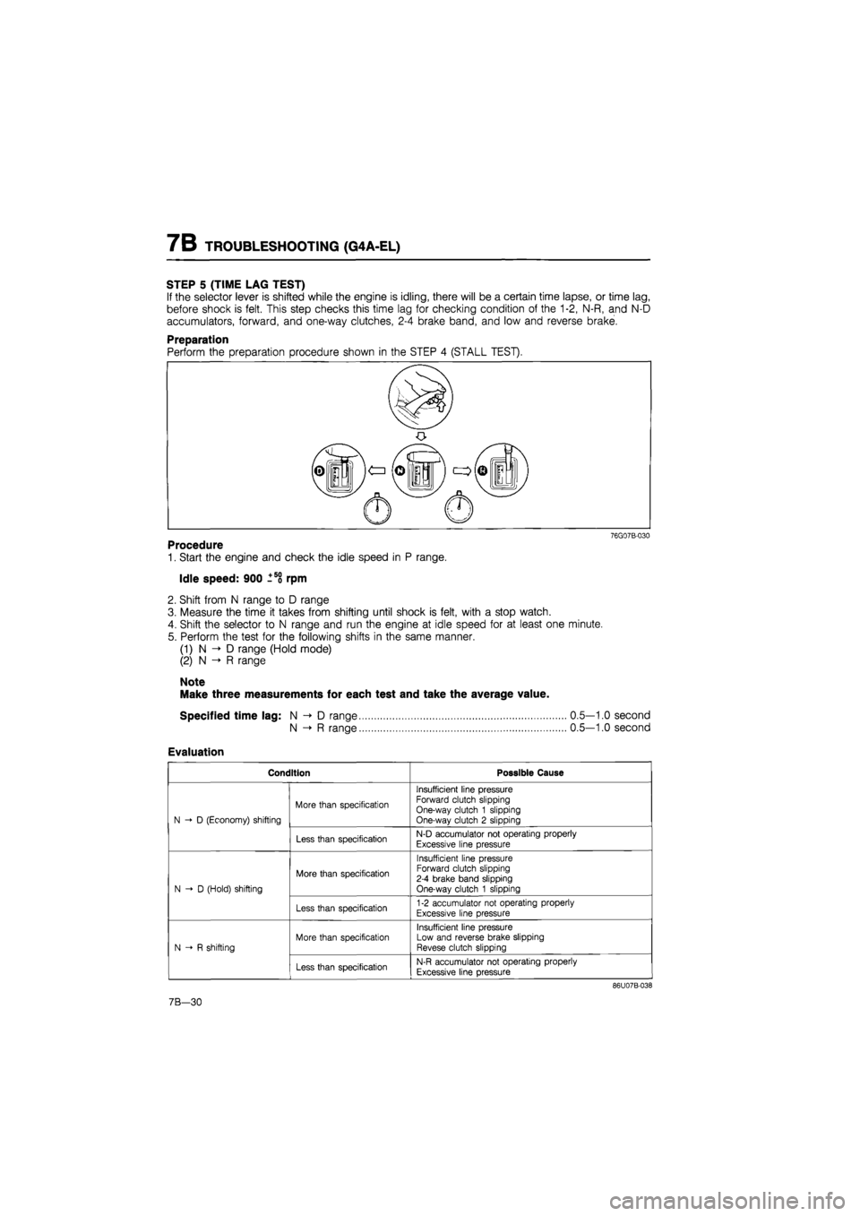
STEP 5 (TIME LAG TEST)
If the selector lever is shifted while the engine is idling, there will be a certain time lapse, or time lag,
before shock is felt. This step checks this time lag for checking condition of the 1-2, N-R, and N-D
accumulators, forward, and one-way clutches, 2-4 brake band, and low and reverse brake.
Preparation
76G07B-030
Procedure
1. Start the engine and check the idle speed in P range.
Idle speed: 900 ±58 rpm
2. Shift from N range to D range
3. Measure the time it takes from shifting until shock is felt, with a stop watch.
4. Shift the selector to N range and run the engine at idle speed for at least one minute.
5. Perform the test for the following shifts in the same manner.
(1) N D range (Hold mode)
(2) N -» R range
Note
Make three measurements for each test and take the average value.
Specified time lag: N -> D range
N -»• R range
Evaluation
Condition Possible Cause
N D (Economy) shifting
More than specification
Insufficient line pressure Forward clutch slipping One-way clutch 1 slipping One-way clutch 2 slipping N D (Economy) shifting
Less than specification N-D accumulator not operating properly
Excessive line pressure
N-D (Hold) shifting
More than specification
Insufficient line pressure Forward clutch slipping 2-4 brake band slipping One-way clutch 1 slipping N-D (Hold) shifting
Less than specification 1-2 accumulator not operating properly
Excessive line pressure
N R shifting
More than specification
Insufficient line pressure Low and reverse brake slipping Revese clutch slipping N R shifting
Less than specification N-R accumulator not operating properly
Excessive line pressure
86U07B-038
0.5—1.0 second
0.5—1.0 second
7B-30
Page 901 of 1865

TROUBLESHOOTING (G4A-EL) 7B
Economy
4.3 (8/8)
3.8-(11/8)
3.4-I .^(6/8)
& c 2.9 5 8.(5/8) - °
S 5 2.4H 1 -i (4/8) « >
0)
05 A
(0/8)
0
i
Lock-up OFF
40 (25) 60 (37) 80 (50) 100 (63) 120 (74) 140 (87) 160 (99)
Vehicle speed km/h (mph)
6. Select D range (Hold mode).
7. Accelerate the vehicle and check 2-3 up- and down-shifts, no 1st, and no OD is obtained and that
the 2-3 shift points are as shown in the D range (Hold) shift diagram.
79G07C-094
7B—35
Page 902 of 1865

7B TROUBLESHOOTING (G4A-EL)
Evaluation
Condition Possible Cause
No 1-2 up- or down-shift Stuck 1-2 shift solenoid valve
Stuck
1
-2 shift valve
No 2-3 up- or down-shift Stuck 2-3 shift solenoid valve Stuck 2-3 shift valve
No 3-OD up- or down-shift Stuck 3-4 shift solenoid valve Stuck 3-4 shift valve
No lock-up shift Stuck lock-up control solenoid valve Stuck lock-up control valve
Incorrect shift point Mis-adjusted throttle sensor Sticking shift valves
Excessive shift shock or slippage
Excessive shift shock Stuck accumulators Stuck or no one-way check orifice
Worn clutches, brakes, or one-way clutch
No engine braking effect Worn clutches or brakes
76G07B-035
Noise and vibration
Drive the vehicle in OD (lock-up), OD (no lock-up), 3rd (Hold) and check for abnormal noise or vibration.
Note
Abnormal noise and vibration can also be caused by the torque converter, drive shaft, or
differential. Therefore, checking of cause must be made with extreme care.
Kick-down
Drive the vehicle in OD, 3rd and 2nd gears and check that kick-down occurs for OD->3, OD->2, OD->1,
3->2, 3-+1, 2-> 1, and the shift points are as shown in the shift diagram.
S Range Test
Shift pattern
1. Shift the selector lever to S range and select the Economy mode.
2. Accelerate the vehicle and check that 1-2 and 2-3 up-shifts and down-shifts are obtained, and that
no overdrive and no lock-up are obtained.
Note
a) Inspections of shift shock and shift point are not necessary because these are the same
as those of the D Range Test.
b)ln S range, the shift patterns for Economy and Power modes are the same.
c) Shift points are the same as those of the D range (Power) shift diagram.
3. While driving in S range (Economy mode) and 3rd gear, select the Hold mode and check that 3rd
gear is held until the 3-2 down-shift point as shown in the S range (Hold) shift diagram is achieved.
4. Accelerate the vehicle with S range (Hold mode) and check that 2nd gear is held.
7B i—36