clutch MAZDA 626 1987 Workshop Manual
[x] Cancel search | Manufacturer: MAZDA, Model Year: 1987, Model line: 626, Model: MAZDA 626 1987Pages: 1865, PDF Size: 94.35 MB
Page 2 of 1865
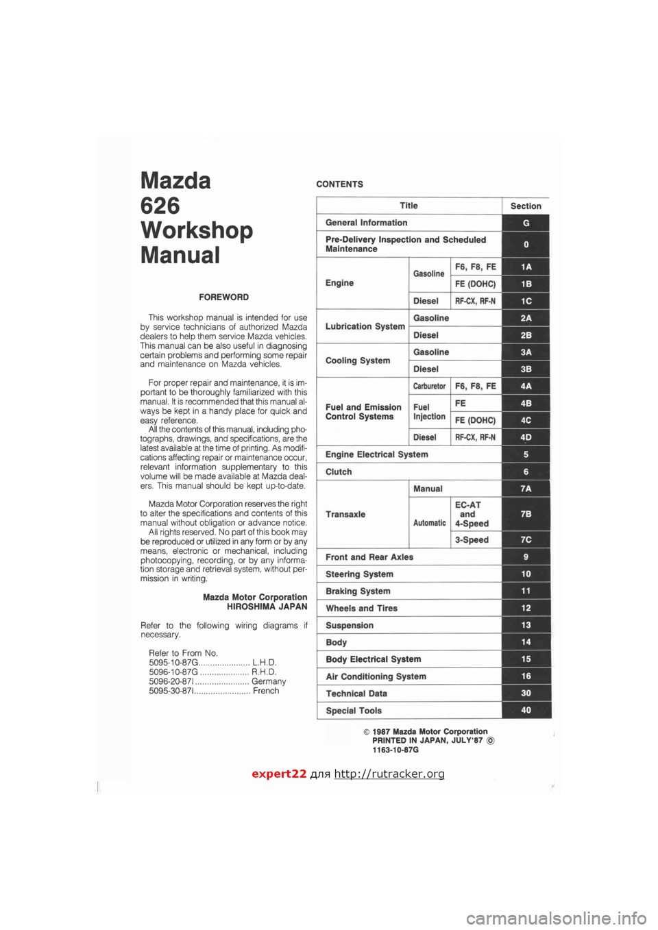
Mazda
626
Workshop
Manual
FOREWORD
This workshop manual is intended for use
by service technicians of authorized Mazda
dealers to help them service Mazda vehicles.
This manual can be also useful in diagnosing
certain problems and performing some repair
and maintenance on Mazda vehicles.
For proper repair and maintenance, it is im-
portant to be thoroughly familiarized with this
manual. It is recommended that this manual al-
ways be kept in a handy place for quick and
easy reference.
All the contents of this manual, including pho-
tographs, drawings, and specifications, are the
latest available at the time of printing. As modifi-
cations affecting repair or maintenance occur,
relevant information supplementary to this
volume will be made available at Mazda deal-
ers. This manual should be kept up-to-date.
Mazda Motor Corporation reserves the right
to alter the specifications and contents of this
manual without obligation or advance notice.
All rights reserved. No part of this book may
be reproduced or utilized in any form or by any
means, electronic or mechanical, including
photocopying, recording, or by any informa-
tion storage and retrieval system, without per-
mission in writing.
Mazda Motor Corporation
HIROSHIMA JAPAN
Refer to the following wiring diagrams if
necessary.
Refer to From No.
5095-10-87 G L.H.D.
5096-10-87 G R.H.D.
5096-20-871 Germany
5095-30-871 French
CONTENTS
Title Section
General Information G
Pre-Delivery Inspection and Scheduled
Maintenance 0
Gasoline F6, F8, FE 1A
Engine
Gasoline
FE (DOHC) 1B
Diesel RF-CX, RF-N 1C
Lubrication System
Gasoline 2A
Lubrication System
Diesel 2B I
Cooling System
Gasoline 3A 1
Cooling System
Diesel 3B
Carburetor F6, F8, FE 4A
Fuel and Emission Fuel FE 4B I
Control Systems Injection FE (DOHC) 4C
Diesel RF-CX, RF-N 4D j
Engine Electrical System 5
Clutch 6
Manual 7A
Transaxle
Automatic
EC-AT
and
4-Speed
7B
3-Speed 7C
Front and Rear Axles 9
Steering System 10
Braking System 11
Wheels and Tires 12
Suspension 13
Body 14 |
Body Electrical System 15
Air Conditioning System 16
Technical Data 30
Special Tools 40
© 1987 Mazda Motor Corporation
PRINTED IN JAPAN, JULY'87 ©
1163-10-87G
expert22 flna http://rutracker.org
Page 14 of 1865
0 PRE-DELIVERY INSPECTION
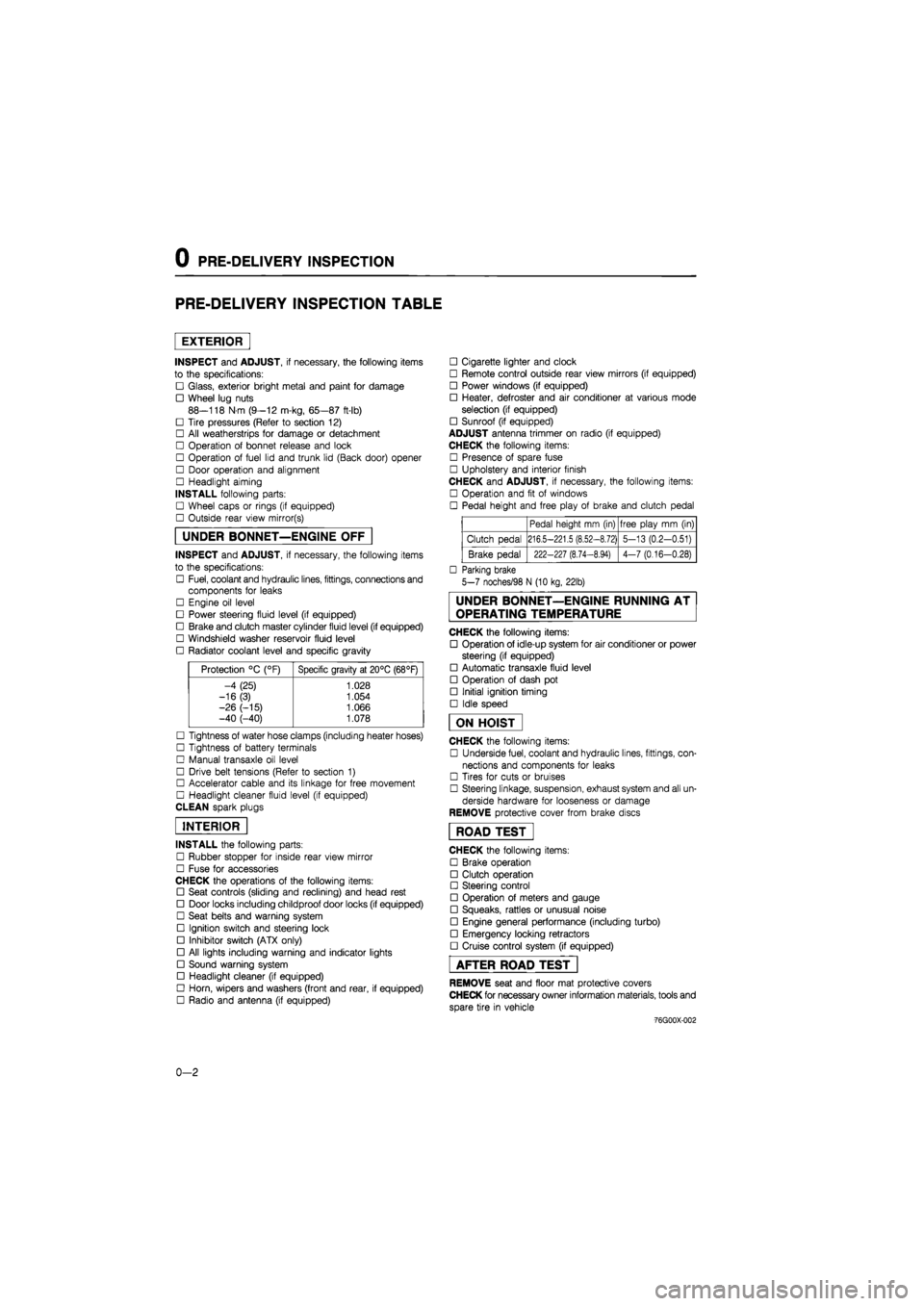
PRE-DELIVERY INSPECTION TABLE
EXTERIOR
INSPECT and ADJUST, if necessary, the following items
to the specifications:
• Glass, exterior bright metal and paint for damage
• Wheel lug nuts
88—118 N m (9—12 m-kg, 65—87 ft-lb)
• Tire pressures (Refer to section 12)
• All weatherstrips for damage or detachment
• Operation of bonnet release and lock
• Operation of fuel lid and trunk lid (Back door) opener
• Door operation and alignment
• Headlight aiming
INSTALL following parts:
• Wheel caps or rings (if equipped)
• Outside rear view mirror(s)
UNDER BONNET—ENGINE OFF
INSPECT and ADJUST, if necessary, the following items
to the specifications:
• Fuel, coolant and hydraulic lines, fittings, connections and
components for leaks
• Engine oil level
• Power steering fluid level (if equipped)
• Brake and clutch master cylinder fluid level (if equipped)
• Windshield washer reservoir fluid level
• Radiator coolant level and specific gravity
Protection °C (°F) Specific gravity at 20°C (68°F)
-4 (25) 1.028
-16(3) 1.054
-26 (-15) 1.066 -40 (-40) 1.078
• Tightness of water hose clamps (including heater hoses)
• Tightness of battery terminals
• Manual transaxle oil level
• Drive belt tensions (Refer to section 1)
• Accelerator cable and its linkage for free movement
• Headlight cleaner fluid level (if equipped)
CLEAN spark plugs
INTERIOR
INSTALL the following parts:
• Rubber stopper for inside rear view mirror
• Fuse for accessories
CHECK the operations of the following items:
• Seat controls (sliding and reclining) and head rest
• Door locks including childproof door locks (if equipped)
• Seat belts and warning system
• Ignition switch and steering lock
• Inhibitor switch (ATX only)
• All lights including warning and indicator lights
• Sound warning system
• Headlight cleaner (if equipped)
• Horn, wipers and washers (front and rear, if equipped)
• Radio and antenna (if equipped)
• Cigarette lighter and clock
• Remote control outside rear view mirrors (if equipped)
• Power windows (if equipped)
• Heater, defroster and air conditioner at various mode
selection (if equipped)
• Sunroof (if equipped)
ADJUST antenna trimmer on radio (if equipped)
CHECK the following items:
• Presence of spare fuse
• Upholstery and interior finish
CHECK and ADJUST, if necessary, the following items:
• Operation and fit of windows
• Pedal height and free play of brake and clutch pedal
Pedal height mm (in) free play mm (in)
Clutch pedal 216.5-221.5 (8.52-8.72) 5-13 (0.2-0.51)
Brake pedal 222-227 (8.74-8.94) 4-7 (0.16-0.28)
• Parking brake
5-7 noches/98 N (10 kg, 22lb)
UNDER BONNET—ENGINE RUNNING AT
OPERATING TEMPERATURE
CHECK the following items:
• Operation of idle-up system for air conditioner or power
steering (if equipped)
• Automatic transaxle fluid level
• Operation of dash pot
• Initial ignition timing
• Idle speed
ON HOIST
CHECK the following items:
• Underside fuel, coolant and hydraulic lines, fittings, con-
nections and components for leaks
• Tires for cuts or bruises
• Steering linkage, suspension, exhaust system and all un-
derside hardware for looseness or damage
REMOVE protective cover from brake discs
ROAD TEST"
CHECK the following items:
• Brake operation
• Clutch operation
• Steering control
• Operation of meters and gauge
• Squeaks, rattles or unusual noise
• Engine general performance (including turbo)
• Emergency locking retractors
• Cruise control system (if equipped)
AFTER ROAD TEST
REMOVE seat and floor mat protective covers
CHECK for necessary owner information materials, tools and
spare tire in vehicle
-76G00X-002
0-2
Page 16 of 1865
0 1 Interval
Procedure & item
Number of Months or km, whichever corns first
©1 ©2 ©3 ©4 Service data and inspection point Page
Interval
Procedure & item
Months — 6 12 18 24 30 36 42 48 ©1 ©2 ©3 ©4 Service data and inspection point Page
Interval
Procedure & item
x 1000 Km 1 10 20 30 40 50 60 70 80 ©1 ©2 ©3 ©4 Service data and inspection point Page
Interval
Procedure & item
Miles x
1000 0.6 6 12 18 24 30 36 42 48
©1 ©2 ©3 ©4 Service data and inspection point Page
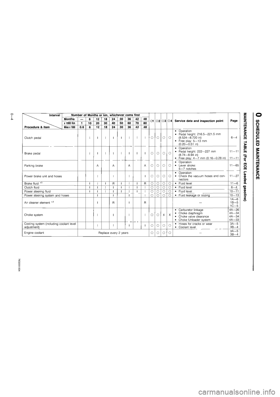
Clutch pedal I 1 I I I I I I O O o o
• Operation
• Pedal height: 216.5—221.5 mm
(8.524—8.720 in) • Free play: 5—13 mm (0.20-0.51 in)
6-4
Brake pedal I 1 I I I I I I O o o o
• Operation
• Pedal height: 222—227 mm (8.74-8.94 in)
• Free play: 4—7 mm (0.16—0.28 in)
11—11
11—11
Parking brake A A A A o o o o
• Operation
• Lever stroke:
5—7 notches
11—65
Power brake unit and hoses 1 I I I o o o o • Operation • Check the vacuum hoses and con-nectors
11—27
Brake fluid " I 1 I R I I I R o o o o • Fluid level 11-6
Clutch fluid I 1 I I I I I I o o o o • Fluid level 6—4
Power steering fluid I 1 I I I I I I
I
o
o"
o
o
o o • Fluid level 10—11
Power steering system and hoses 1 I I
I I
I
o
o"
o
o o o • Fluid leakage or oozing 10—13
Air cleaner element *3 1 R I R —
1A—6 1B—5 1C—5
Choke system 1 I I o o X X
• Carburetor linkage • Choke diaphragm • Choke valve clearance
• Choke Unloader system
4A-26 4A—34 4A—34 4A—33
Cooling system (including coolant level adjustment) 1 I I I o o o o • Hoses for cracks or wear
• Coolant level
3A—5 3B—4
Engine coolant Replace every 2 years o o o o -3A-5 3B-4
Page 22 of 1865
0
1
o
interval
Procedure & Item
Number of Months or km, whichever corns first
©1 ©2 ©3 ©4 Service data and inspection point Page
interval
Procedure & Item
Months — 6 12 18 24 30 36 42 48 ©1 ©2 ©3 ©4 Service data and inspection point Page
interval
Procedure & Item
x
1000 Km
1 10 20 30 40 50 60 70 80 ©1 ©2 ©3 ©4 Service data and inspection point Page
interval
Procedure & Item
Miles x 1000
0.6 6 12 18 24 30 36 42 48
©1 ©2 ©3 ©4 Service data and inspection point Page
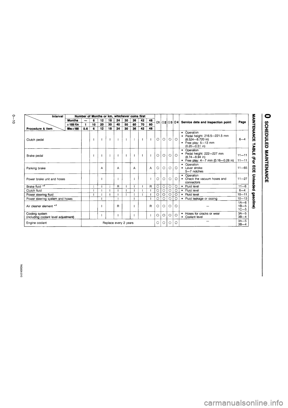
Clutch pedal I I I I I I I I O o o o
• Operation
• Pedal height: 216.5—221.5 mm (8.524—8.720 in)
• Free play: 5—13 mm (0.20—0.51 in)
6-4
Brake pedal I I I I I I I I O o o o
• Operation • Pedal height: 222—227 mm (8.74—8.94 in)
• Free play: 4—7 mm (0.16—0.28 in)
11-11
11—11
Parking brake A A A A o o o o
• Operation • Lever stroke: 5—7 notches
11-65
Power brake unit and hoses I I I I o o o o
• Operation • Check the vacuum hoses and connectors
11—27
Brake fluid *5 I I I R I I I R 0 o o o • Fluid level 11—6
Clutch fluid I I I I I I I I o o o 0 • Fluid level 6-4
Power steering fluid I I I I I I I I o o o o • Fluid level 10—11
Power steering system and hoses I I I I 0 o o 0 • Fluid leakage or oozing 10—13
Air cleaner element *3 I R I R o o o o —
1 A—6 1B—5 1C-5
Cooling system (including coolant level adjustment) I I I I o o o o • Hoses for cracks or wear • Coolant level
3A—5
3B-4
Engine coolant Replace every 2 years 0 o 0 0 — 3A-5 3B—4
a> a o o X o o
Page 28 of 1865
0 1
CO
interval Number of Months or km, whichever corns first
Months — 6 12 18 24 30 36 42 48 ©1 ©2 ©3 ©4 Service data and inspection point Page x 1000 Km 1 10 20 30 40 50 60 70 80 ©1 ©2 ©3 ©4 Service data and inspection point Page
Procedure & item Miles x 1000 0.6 6 12 18 24 30 36 42 48
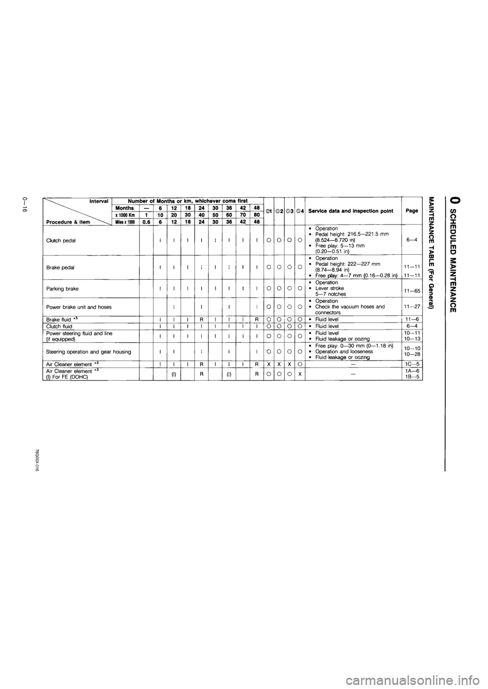
Clutch pedal I I I I I I I I O o o o
• Operation • Pedal height: 216.5—221.5 mm (8.524—8.720 in) • Free play: 5—13 mm (0.20—0.51 in)
6—4
Brake pedal I I I I I I I I o o o o
• Operation
• Pedal height: 222—227 mm (8.74—8.94 in)
• Free play: 4—7 mm (0.16—0.28 in)
11-11
11—11
Parking brake I I I I I I I I o o o o
• Operation • Lever stroke 5—7 notches 11-65
Power brake unit and hoses I I I I o o o o
• Operation • Check the vacuum hoses and connectors
11—27
Brake fluid *s I I I R I I I R o o o o • Fluid level 11-6
Clutch fluid I I I I I I I I o o o o • Fluid level 6-4
Power steering fluid and line (if equipped) I I I I I I I I o o o o • Fluid level • Fluid leakage or oozing
10—11
10—13
Steering operation and gear housing I I I I I o o o o
• Free play: 0—30 mm (0—1.18 in) • Operation and looseness • Fluid leakage or oozing
10—10
10-28
Air Cleaner element *3 I I I R I I I R X X X o — 1C—5
Air Cleaner element *3 (1) For FE (DOHC) (0 R (I) R o o o X — 1A—6
1B—5
Page 37 of 1865
TROUBLESHOOTING GUIDE 1 A
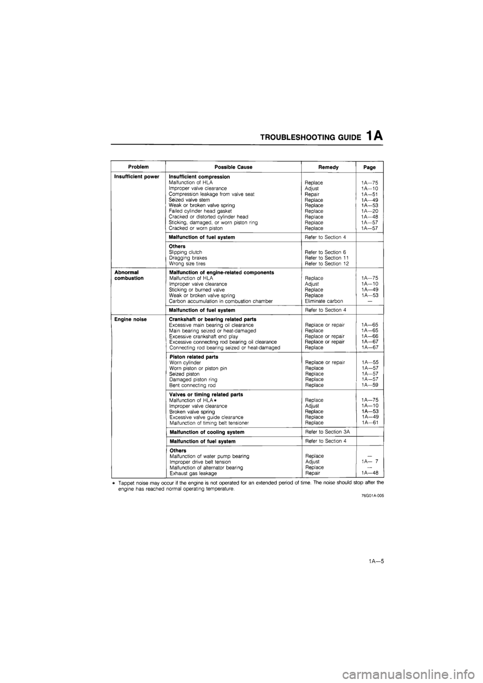
Problem Possible Cause Remedy Page
Insufficient power Insufficient compression Malfunction of HLA Improper valve clearance Compression leakage from valve seat Seized valve stem Weak or broken valve spring Failed cylinder head gasket Cracked or distorted cylinder head Sticking, damaged, or worn piston ring Cracked or worn piston
Replace
Adjust
Repair
Replace Replace Replace Replace Replace Replace
1A—75 1A—10
1
A—51 1A—49 1A—53
1
A—20 1A—48 1A—57
1
A—57
Malfunction of fuel system Refer to Section 4
Others Slipping clutch Dragging brakes Wrong size tires
Refer to Section 6 Refer to Section 11 Refer to Section 12
Abnormal
combustion
Malfunction of engine-related components Malfunction of HLA
Improper valve clearance Sticking or burned valve
Weak or broken valve spring Carbon accumulation in combustion chamber
Replace Adjust Replace Replace
Eliminate carbon
1
A—75 1A—10 1A—49 1A—53
Malfunction of fuel system Refer to Section 4
Engine noise Crankshaft or bearing related parts
Excessive main bearing oil clearance Main bearing seized or heat-damaged Excessive crankshaft end play Excessive connecting rod bearing oil clearance Connecting rod bearing seized or heat-damaged
Replace or repair Replace
Replace or repair Replace or repair Replace
1A—65
1
A—65 1A—66 1A—67
1
A—67
Piston related parts Worn cylinder Worn piston or piston pin Seized piston Damaged piston ring Bent connecting rod
Replace or repair
Replace
Replace Replace Replace
1A—55
1
A—57
1
A—57
1
A—57 1A—59
Valves or timing related parts Malfunction of HLA* Improper valve clearance Broken valve spring Excessive valve guide clearance Malfunction of timing belt tensioner
Replace Adjust
Replace Replace Replace
1A—75 1A—10 1A—53 1A—49 1A—61
Malfunction of cooling system Refer to Section 3A
Malfunction of fuel system Refer to Section 4
Others Malfunction of water pump bearing Improper drive belt tension Malfunction of alternator bearing Exhaust gas leakage
Replace Adjust Replace Repair
1 A— 7
1
A—48
* Tappet noise may occur if the engine is not operated for an extended period of time. The noise should stop after the
engine has reached normal operating temperature.
76G01A-005
1A—5
Page 67 of 1865
REMOVAL 1A
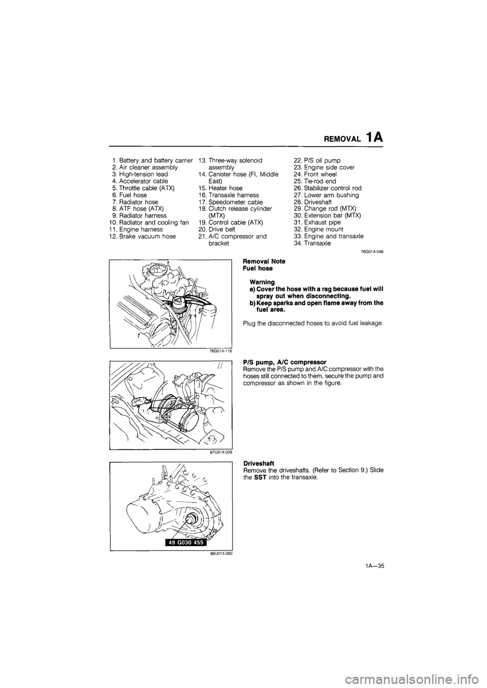
1. Battery and battery carrier 13. Three-way solenoid 22. P/S oil pump
2. Air cleaner assembly assembly 23. Engine side cover
3. High-tension lead 14. Canister hose (Fl, Middle 24. Front wheel
4. Accelerator cable East) 25. Tie-rod end
5. Throttle cable (ATX) 15. Heater hose 26. Stabilizer control rod
6. Fuel hose 16. Transaxle harness 27. Lower arm bushing
7. Radiator hose 17. Speedometer cable 28. Driveshaft
8. ATF hose (ATX) 18. Clutch release cylinder 29. Change rod (MTX)
9. Radiator harness (MTX) 30. Extension bar (MTX)
10. Radiator and cooling fan 19. Control cable (ATX) 31. Exhaust pipe
11. Engine harness 20. Drive belt 32. Engine mount
12. Brake vacuum hose 21. A/C compressor and 33. Engine and transaxle
bracket 34. Transaxle
76G01A-046
Removal Note
Fuel hose
Warning
a) Cover the hose with a rag because fuel will
spray out when disconnecting.
b) Keep sparks and open flame away from the
fuel area.
Plug the disconnected hoses to avoid fuel leakage.
76G01A-11E
P/S pump, A/C compressor
Remove the P/S pump and A/C compressor with the
hoses still connected to them, secure the pump and
compressor as shown in the figure.
67U01X-029
Driveshaft
Remove the driveshafts. (Refer to Section 9.) Slide
the SST into the transaxle.
86U01X-060
1A—35
Page 76 of 1865

1 A DISASSEMBLY (CYLINDER BLOCK)
CYLINDER BLOCK—I
1. Clutch cover (MTX), Backing plate (ATX)
2. Clutch disc (MTX), Drive plate (ATX)
3. Flywheel (MTX), Adaptor (ATX)
4. End plate
5. Oil pan
76G01A-051
6. Oil strainer
7. Stiffener (FE 8-valve...only ECE, 12-valve)
8. Rear cover
9. Water pump assembly
10. Oil pump assembly
1A—44
Page 77 of 1865

DISASSEMBLY (CYLINDER BLOCK) 1 A
76G01A-125
Disassembly Note
Clutch cover, flywheel (MTX) or drive plate (ATX)
Remove the clutch cover and flywheel (MTX), or drive
plate (ATX) with the SST.
Oil pan
1. Remove the oil pan mounting bolts.
2. Insert a scraper or a suitable tool between the oil
pan and the stiffener or the cylinder block to sep-
arate them.
3. Remove the oil pan.
Caution
Do not bend the oil pan when prying loose.
76G01A-052
1A—45
Page 104 of 1865

1 A
DISASSEMBLY
(CYLINDER BLOCK)
86U01X-141
86U01X-142
Clutch Disc and Clutch Cover (MTX)
Install the clutch disc and clutch cover using the SST.
(Refer to Section 6.)
Tightening torque:
22—32 N-m (2.2—3.3 m-kg, 16—24 ft-lb)
Water Pump
1. Remove all dirt, grease, and other material from
the water pump mounting surface.
2. Place a new O-ring in position.
Caution
Do not reuse the original O-ring.
3. Install the water pump.
Tightening torque:
19—25 N-m (1.9—2.6 m-kg, 14—19 ft-lb)
7BU01B-103
1A—72