lock MAZDA 626 1987 Workshop Manual
[x] Cancel search | Manufacturer: MAZDA, Model Year: 1987, Model line: 626, Model: MAZDA 626 1987Pages: 1865, PDF Size: 94.35 MB
Page 4 of 1865
G IMPORTANT INFORMATION/FUNDAMENTAL PROCEDURES
IMPORTANT INFORMATION
BASIC ASSUMPTIONS
This workshop manual assumes that you have arid know how to properly use certain special tools
which are necessary for the safe and efficient performance of service operations on Mazda vehicles.
The manual also assumes that you are familiar generally with automobile systems and basic service
and repair procedures. You should not attempt to use this manual unless these assumptions are cor-
rect and you understand the consequences described below.
SAFETY RISK
This manual contains certain notes, warnings, etc., which you should carefully read and follow in or-
der to eliminate the risk of personal injury to yourself or others and the risk of improper service which
may damage the vehicle or render it unsafe. The fact that there are no such notes, etc., with respect
to any specific service method does not mean that there is no possibility that personal safety or vehicle
safety will be jeopardized by the use of incorrect methods or tools.
POSSIBLE LOSS OF WARRANTY
The manufacturer's warranty on Mazda vehicles and engines can be voided if improper service or
repairs are performed by persons other than an authorized Mazda dealer.
FUNDAMENTAL PROCEDURES
As you read through the procedure, you will come
across NOTES, CAUTIONS, and WARNINGS. Each
one is there for a specific purpose. NOTES give you
added information that will help you to complete a
particular procedure. CAUTIONS are given to pre-
vent you from making an error that could damage
the vehicle. WARNINGS remind you to be espe-
cially careful in those areas where carelessness can
cause personal injury. The following list contains
some general WARNINGS that you should follow
when you work on a vehicle.
PROTECTION OF THE VEHICLE
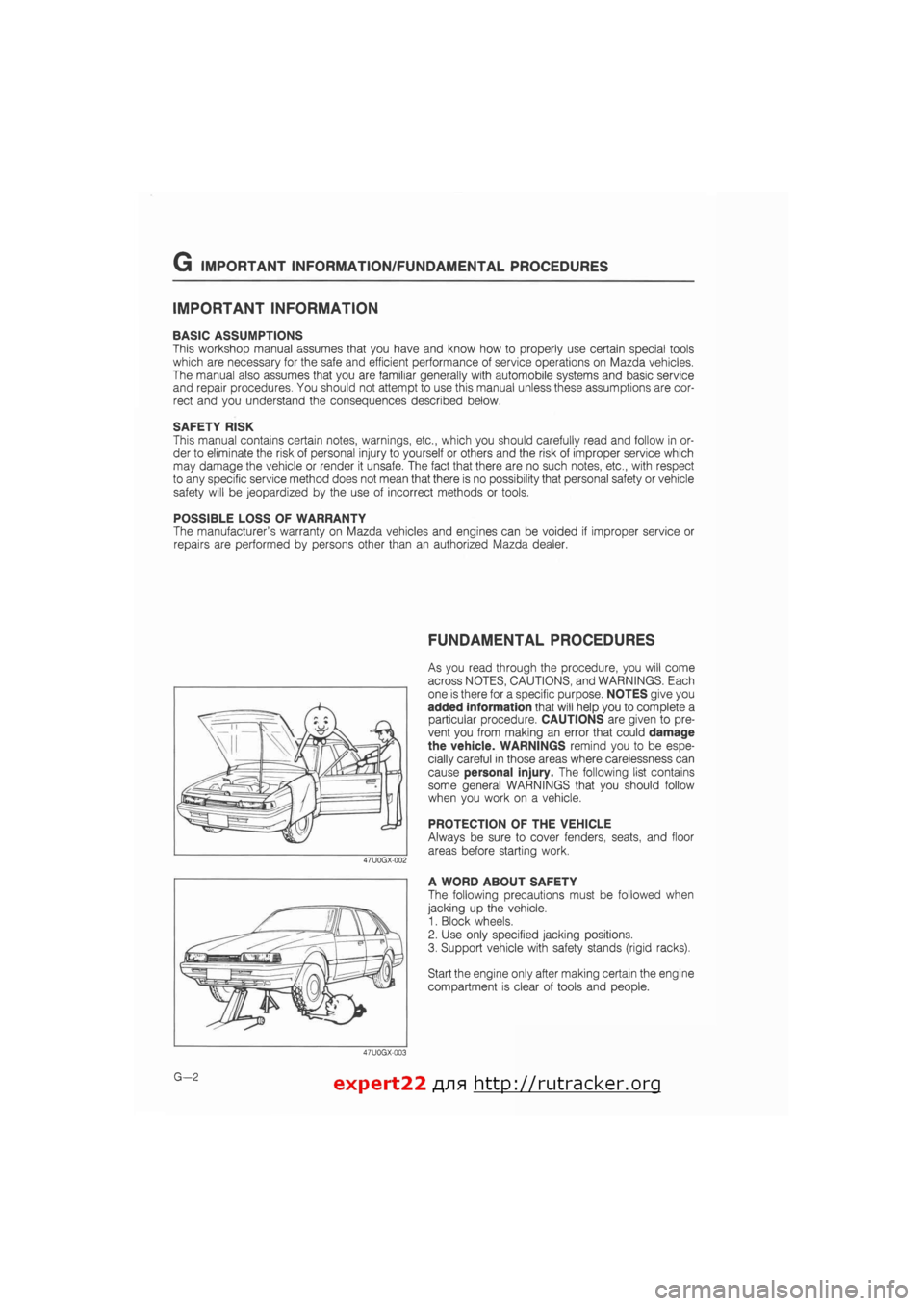
Always be sure to cover fenders, seats, and floor
areas before starting work.
A WORD ABOUT SAFETY
The following precautions must be followed when
jacking up the vehicle.
1. Block wheels.
2. Use only specified jacking positions.
3. Support vehicle with safety stands (rigid racks).
Start the engine only after making certain the engine
compartment is clear of tools and people.
G—2 expert22 fl/i* http://rutracker.org
Page 6 of 1865
G FUNDAMENTAL PROCEDURES
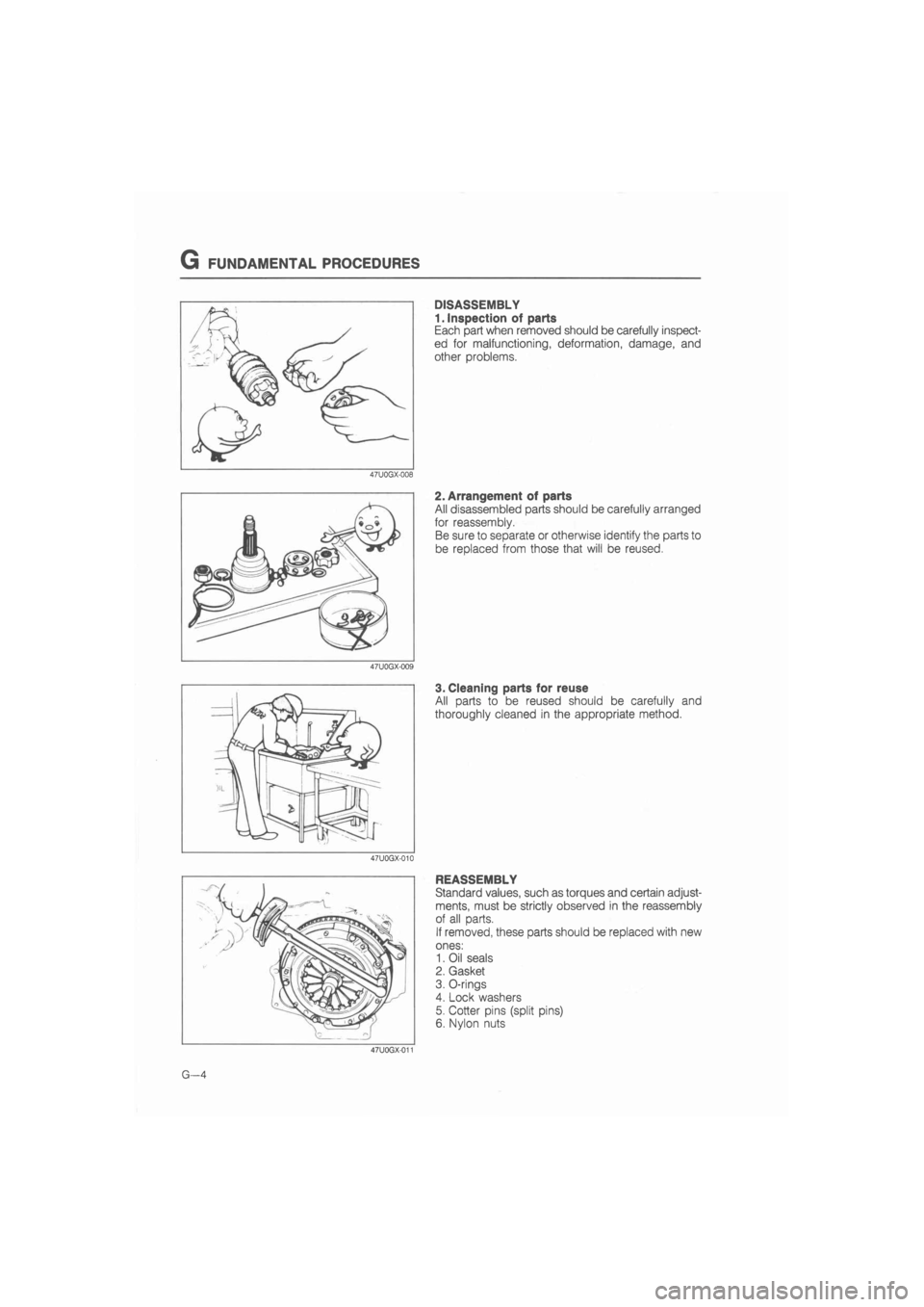
DISASSEMBLY
1. Inspection of parts
Each part when removed should be carefully inspect-
ed for malfunctioning, deformation, damage, and
other problems.
2. Arrangement of parts
All disassembled parts should be carefully arranged
for reassembly.
Be sure to separate or otherwise identify the parts to
be replaced from those that will be reused.
3. Cleaning parts for reuse
All parts to be reused should be carefully and
thoroughly cleaned in the appropriate method.
REASSEMBLY
Standard values, such as torques and certain adjust-
ments, must be strictly observed in the reassembly
of all parts.
If removed, these parts should be replaced with new
ones:
1. Oil seals
2. Gasket
3. O-rings
4. Lock washers
5. Cotter pins (split pins)
6. Nylon nuts
G—4
Page 7 of 1865
FUNDAMENTAL PROCEDURES G
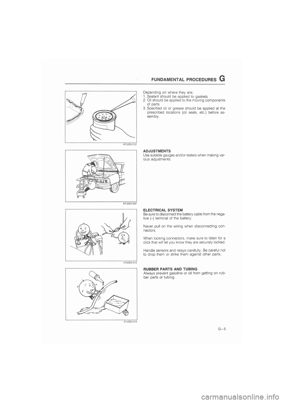
Depending on where they are;
1. Sealant should be applied to gaskets
2. Oil should be applied to the moving components
of parts
3. Specified oil or grease should be applied at the
prescribed locations (oil seals, etc.) before as-
sembly.
47U0GX-012
ADJUSTMENTS
Use suitable gauges and/or testers when making var-
ious adjustments.
67U0GX-002
ELECTRICAL SYSTEM
Be sure to disconnect the battery cable from the nega-
tive (-) terminal of the battery.
Never pull on the wiring when disconnecting con-
nectors.
When locking connectors, make sure to listen for a
click that will let you know they are securely locked.
Handle sensors and relays carefully. Be careful not
to drop them or strike them against other parts.
47U0GX-014
RUBBER PARTS AND TUBING
Always prevent gasoline or oil from getting on rub-
ber parts or tubing.
47U0GX-015
G—5
Page 11 of 1865
CHASSIS NUMBER LOCATION/ABBREVIATIONS/UNITS G
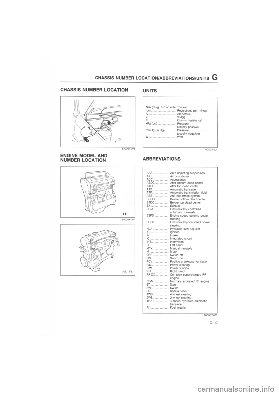
CHASSIS NUMBER LOCATION UNITS
67U0GX-005
ENGINE MODEL AND
NUMBER LOCATION
Nm (m-kg, ft-lb or in-lb). Torque
rpm Revolutions per minute A Ampere(s) V Volt(s) U Ohm(s) (resistance) kPa (psi) Pressure
(usually positive) mrriHg (in Hg) Pressure
(usually negative) W Watt
76G0GX-004
ABBREVIATIONS
67U0GX-007
AAS Auto adjusting suspension A/C Air conditioner ACC Accessories ABDC After bottom dead center ATDC After top dead center ATX Automatic transaxle ATF Automatic transmission fluid ABS Anti-lock brake system BBDC Before bottom dead center BTDC Before top dead center EX Exhaust EC-AT Electronically controlled automatic transaxle ESPS Engine speed sensing power steering EC PS Electronically-controlled power steering HLA Hydraulic lash adjuster IG Ignition IN Intake IC Integrated circuit INT Intermittent LH Left hand
MTX Manual transaxle M Motor OFF Switch off ON Switch on PCV Positive crankcase ventilation P/S Power steering P/W Power window RH Right hand RF-CX Comprex supercharged RF
engine
RF-N Normally aspirated RF engine ST Start sw Switch SST Special tools 4WS 4-wheel steering
PWS 2-wheel steering
4HAT 4-speed hydraulic automatic
transaxle Fl Fuel injection
76GQGX-005
G—9
Page 14 of 1865
0 PRE-DELIVERY INSPECTION
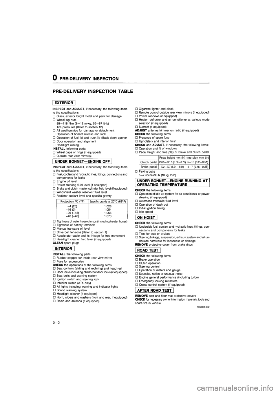
PRE-DELIVERY INSPECTION TABLE
EXTERIOR
INSPECT and ADJUST, if necessary, the following items
to the specifications:
• Glass, exterior bright metal and paint for damage
• Wheel lug nuts
88—118 N m (9—12 m-kg, 65—87 ft-lb)
• Tire pressures (Refer to section 12)
• All weatherstrips for damage or detachment
• Operation of bonnet release and lock
• Operation of fuel lid and trunk lid (Back door) opener
• Door operation and alignment
• Headlight aiming
INSTALL following parts:
• Wheel caps or rings (if equipped)
• Outside rear view mirror(s)
UNDER BONNET—ENGINE OFF
INSPECT and ADJUST, if necessary, the following items
to the specifications:
• Fuel, coolant and hydraulic lines, fittings, connections and
components for leaks
• Engine oil level
• Power steering fluid level (if equipped)
• Brake and clutch master cylinder fluid level (if equipped)
• Windshield washer reservoir fluid level
• Radiator coolant level and specific gravity
Protection °C (°F) Specific gravity at 20°C (68°F)
-4 (25) 1.028
-16(3) 1.054
-26 (-15) 1.066 -40 (-40) 1.078
• Tightness of water hose clamps (including heater hoses)
• Tightness of battery terminals
• Manual transaxle oil level
• Drive belt tensions (Refer to section 1)
• Accelerator cable and its linkage for free movement
• Headlight cleaner fluid level (if equipped)
CLEAN spark plugs
INTERIOR
INSTALL the following parts:
• Rubber stopper for inside rear view mirror
• Fuse for accessories
CHECK the operations of the following items:
• Seat controls (sliding and reclining) and head rest
• Door locks including childproof door locks (if equipped)
• Seat belts and warning system
• Ignition switch and steering lock
• Inhibitor switch (ATX only)
• All lights including warning and indicator lights
• Sound warning system
• Headlight cleaner (if equipped)
• Horn, wipers and washers (front and rear, if equipped)
• Radio and antenna (if equipped)
• Cigarette lighter and clock
• Remote control outside rear view mirrors (if equipped)
• Power windows (if equipped)
• Heater, defroster and air conditioner at various mode
selection (if equipped)
• Sunroof (if equipped)
ADJUST antenna trimmer on radio (if equipped)
CHECK the following items:
• Presence of spare fuse
• Upholstery and interior finish
CHECK and ADJUST, if necessary, the following items:
• Operation and fit of windows
• Pedal height and free play of brake and clutch pedal
Pedal height mm (in) free play mm (in)
Clutch pedal 216.5-221.5 (8.52-8.72) 5-13 (0.2-0.51)
Brake pedal 222-227 (8.74-8.94) 4-7 (0.16-0.28)
• Parking brake
5-7 noches/98 N (10 kg, 22lb)
UNDER BONNET—ENGINE RUNNING AT
OPERATING TEMPERATURE
CHECK the following items:
• Operation of idle-up system for air conditioner or power
steering (if equipped)
• Automatic transaxle fluid level
• Operation of dash pot
• Initial ignition timing
• Idle speed
ON HOIST
CHECK the following items:
• Underside fuel, coolant and hydraulic lines, fittings, con-
nections and components for leaks
• Tires for cuts or bruises
• Steering linkage, suspension, exhaust system and all un-
derside hardware for looseness or damage
REMOVE protective cover from brake discs
ROAD TEST"
CHECK the following items:
• Brake operation
• Clutch operation
• Steering control
• Operation of meters and gauge
• Squeaks, rattles or unusual noise
• Engine general performance (including turbo)
• Emergency locking retractors
• Cruise control system (if equipped)
AFTER ROAD TEST
REMOVE seat and floor mat protective covers
CHECK for necessary owner information materials, tools and
spare tire in vehicle
-76G00X-002
0-2
Page 33 of 1865
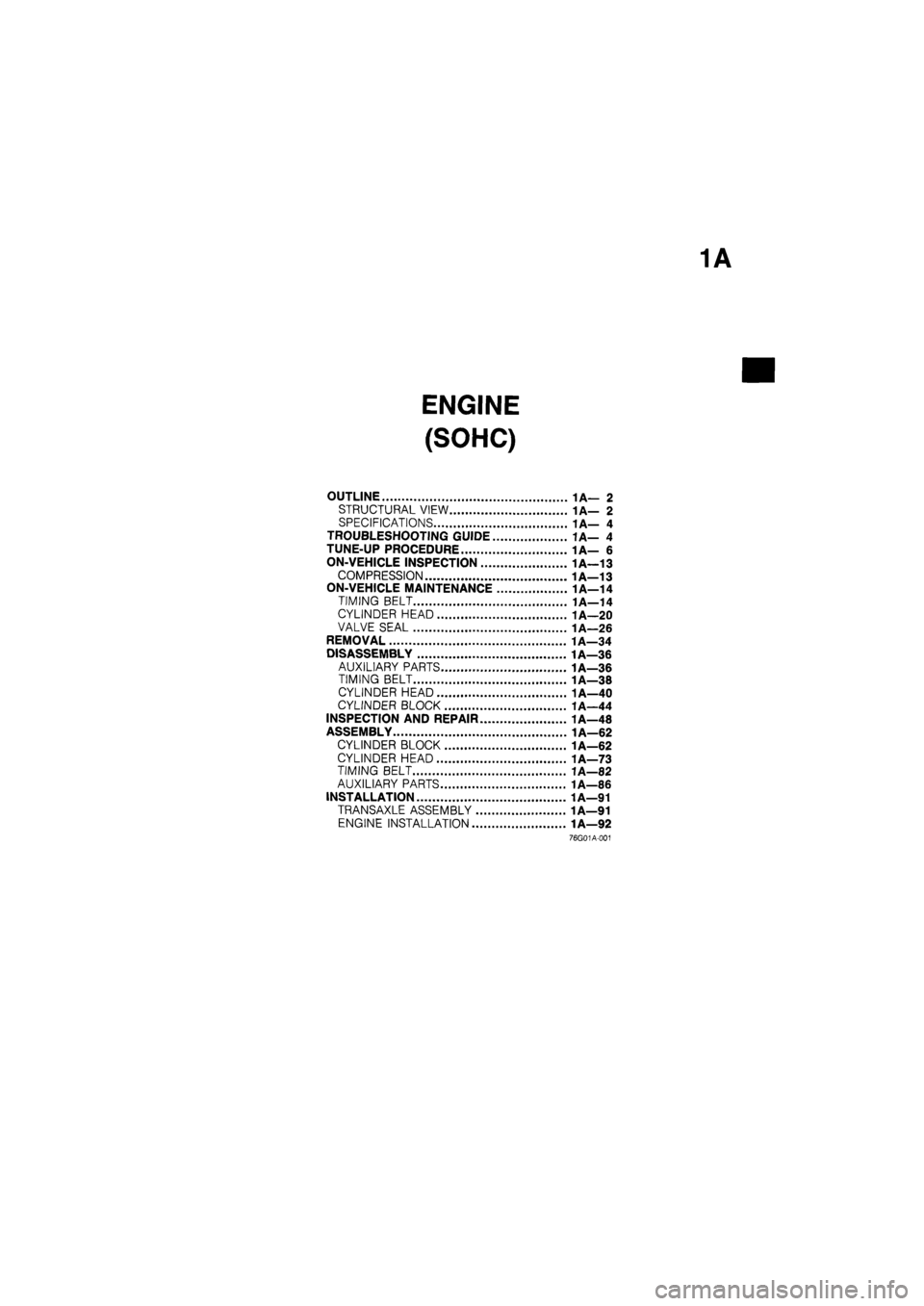
ENGINE
(SOHC)
OUTLINE 1A— 2
STRUCTURAL VIEW 1A— 2
SPECIFICATIONS 1A— 4
TROUBLESHOOTING GUIDE 1A— 4
TUNE-UP PROCEDURE 1A— 6
ON-VEHICLE INSPECTION 1A-13
COMPRESSION 1A—13
ON-VEHICLE MAINTENANCE 1A—14
TIMING BELT 1A—14
CYLINDER HEAD 1A—20
VALVE SEAL 1A—26
REMOVAL 1A—34
DISASSEMBLY 1A—36
AUXILIARY PARTS 1A—36
TIMING BELT 1A—38
CYLINDER HEAD 1A—40
CYLINDER BLOCK 1A—44
INSPECTION AND REPAIR 1A—48
ASSEMBLY 1A—62
CYLINDER BLOCK 1A—62
CYLINDER HEAD 1A—73
TIMING BELT 1A—82
AUXILIARY PARTS 1A—86
INSTALLATION 1A—91
TRANSAXLE ASSEMBLY 1A—91
ENGINE INSTALLATION 1A—92
76G01A-001
Page 39 of 1865
1A TUNE-UP PROCEDURE
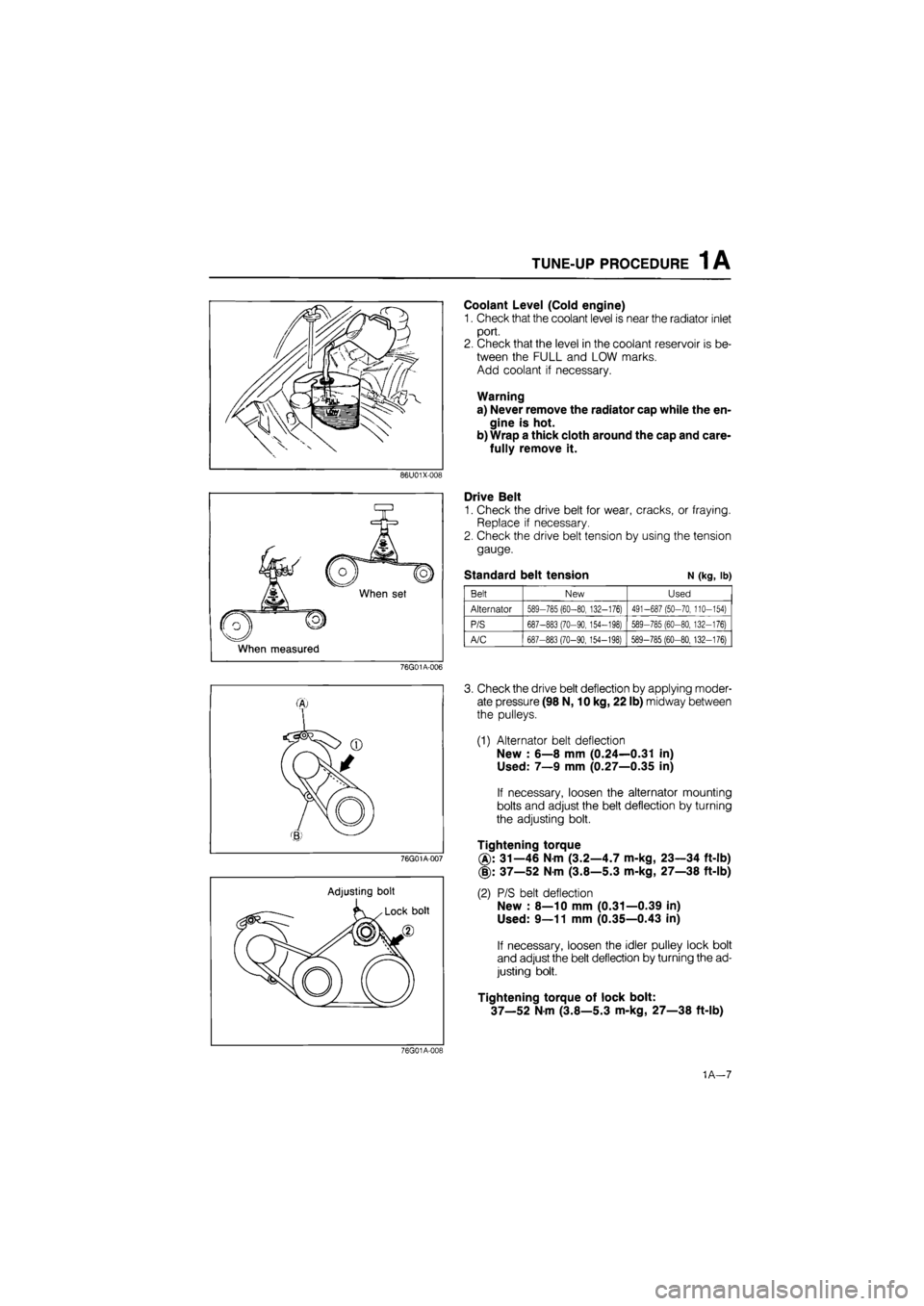
Coolant Level (Cold engine)
1. Check that the coolant level is near the radiator inlet
port.
2. Check that the level in the coolant reservoir is be-
tween the FULL and LOW marks.
Add coolant if necessary.
Warning
a) Never remove the radiator cap while the en-
gine is hot.
b) Wrap a thick cloth around the cap and care-
fully remove it.
86U01X-008
When set
When measured
Drive Belt
1. Check the drive belt for wear, cracks, or fraying.
Replace if necessary.
2. Check the drive belt tension by using the tension
gauge.
Standard belt tension N (kg, lb)
Belt New Used
Alternator 589-785 (60-80, 132-176) 491-687 (50-70, 110-154)
P/S 687-883 (70-90, 154-198) 589-785 (60-80, 132-176)
A/C 687-883 (70-90,154-198) 589-785 (60-80, 132-176)
76G01A-006
76G01A-007
Adjusting bolt
3. Check the drive belt deflection by applying moder-
ate pressure (98 N, 10 kg, 22 lb) midway between
the pulleys.
(1) Alternator belt deflection
New : 6—8 mm (0.24—0.31 in)
Used: 7—9 mm (0.27—0.35 in)
If necessary, loosen the alternator mounting
bolts and adjust the belt deflection by turning
the adjusting bolt.
Tightening torque
31—46 Nm (3.2—4.7 m-kg, 23—34 ft-lb)
(§): 37—52 Nm (3.8—5.3 m-kg, 27—38 ft-lb)
(2) P/S belt deflection
New : 8—10 mm (0.31—0.39 in)
Used: 9—11 mm (0.35—0.43 in)
If necessary, loosen the idler pulley lock bolt
and adjust the belt deflection by turning the ad-
justing bolt.
Tightening torque of lock bolt:
37—52 Nm (3.8—5.3 m-kg, 27—38 ft-lb)
76G01A-019
1A—7
Page 42 of 1865

1A TUNE-UP PROCEDURE
No.1 IN No.2 IN
No.1 EX No.3 EX
76G01A-015
Adjust bolt
^N^^^^^Lock nut
SsKs&b ' Valve
Camshaft >Nw clearance
76G01A-016
76G01A-017
Valve Clearance (8-valve)
1. Warm up the engine to the normal operating tem-
perature.
2. With the piston of the No.1 cylinder at TDC of com-
pression stroke.
Adjust the valve clearance as shown in the figure.
Valve clearance (valve side)
IN : 0.30 mm (0.012 in)
EX: 0.30 mm (0.012 in)
3. Turn the crankshaft one full turn so that the piston
of the No.4 cylinder is at TDC of compression
stroke.
Adjust the clearances of the remaining valves.
Ignition Timing
1. Warm up the engine and run it at idle.
2. Turn all electric loads OFF.
3. Connect a timing light tester.
4. Disconnect the vacuum hose from the vacuum
control, and plug the hose.
5. Check that the ignition timing mark (yellow) on the
crankshaft pulley and the timing mark on the tim-
ing belt cover are aligned.
Ignition timing: 6° ±
1
° BTDC (at idle speed)
6. If necessary adjust the ignition timing by turning
the distributor.
69G01B-518
1A—10
Page 49 of 1865

ON-VEHICLE MAINTENANCE (TIMING BELT) 1 A
76G01A-027
76G01B-024
76G01A-028
/Jf
ry.
2. Check that the mating mark of the camshaft pul-
ley is aligned with the timing mark. If it is not
aligned, turn the camshaft to align.
Note
For FE engine, align "2" mark.
For F8, F6 engine, align "3" mark.
3. Install the timing belt tensioner and spring. Tem-
porarily secure it with the spring fully extended.
Caution
Do not damage the pulleys when securing the
tensioner pulley.
4. Install the timing belt. (Keep the tension side of belt
as tight as possible).
Caution
a) If the timing belt is being reused, it must be
reinstalled to rotate in the original direction.
b) Check that there is no oil, grease, or dirt on
the timing belt.
5. Loosen the tensioner lock bolt.
6. Turn the crankshaft twice in the direction of rota-
tion, and align the mating marks.
7. Check that the timing marks are correctly aligned.
If not aligned, remove the timing belt tensioner and
timing belt, and repeat steps 1—6.
69G01B-027
1A-17
Page 50 of 1865

1 A ON-VEHICLE MAINTENANCE (TIMING BELT)
8. Tighten the timing belt tensioner lock bolt.
Tightening torque:
37—52 N-m (3.8—5.3 m-kg, 27—38 ft-lb)
69G01B-028
9. Check the timing belt deflection. If the deflection
is not correct, repeat the adjustment from step 5
above.
Timing belt deflection
FE: 5.5—6.5 mm (0.22—0.26 in)
F8, F6: 4.0—5.0 mm (0.16—0.20 in)
/98 N (10 kg, 22 lb)
Caution
Be sure not to apply tension other than that
of the tensioner spring.
76G01A-029
Baffle plate
Install the baffle plate as shown in the figure.
69G01B-030
Drive belt
Install each drive belt, and check the belt deflection.
(Refer to page 1A—7.)
76G01A-030
1A—18