maintenance schedule MAZDA 626 1987 Workshop Manual
[x] Cancel search | Manufacturer: MAZDA, Model Year: 1987, Model line: 626, Model: MAZDA 626 1987Pages: 1865, PDF Size: 94.35 MB
Page 2 of 1865

Mazda
626
Workshop
Manual
FOREWORD
This workshop manual is intended for use
by service technicians of authorized Mazda
dealers to help them service Mazda vehicles.
This manual can be also useful in diagnosing
certain problems and performing some repair
and maintenance on Mazda vehicles.
For proper repair and maintenance, it is im-
portant to be thoroughly familiarized with this
manual. It is recommended that this manual al-
ways be kept in a handy place for quick and
easy reference.
All the contents of this manual, including pho-
tographs, drawings, and specifications, are the
latest available at the time of printing. As modifi-
cations affecting repair or maintenance occur,
relevant information supplementary to this
volume will be made available at Mazda deal-
ers. This manual should be kept up-to-date.
Mazda Motor Corporation reserves the right
to alter the specifications and contents of this
manual without obligation or advance notice.
All rights reserved. No part of this book may
be reproduced or utilized in any form or by any
means, electronic or mechanical, including
photocopying, recording, or by any informa-
tion storage and retrieval system, without per-
mission in writing.
Mazda Motor Corporation
HIROSHIMA JAPAN
Refer to the following wiring diagrams if
necessary.
Refer to From No.
5095-10-87 G L.H.D.
5096-10-87 G R.H.D.
5096-20-871 Germany
5095-30-871 French
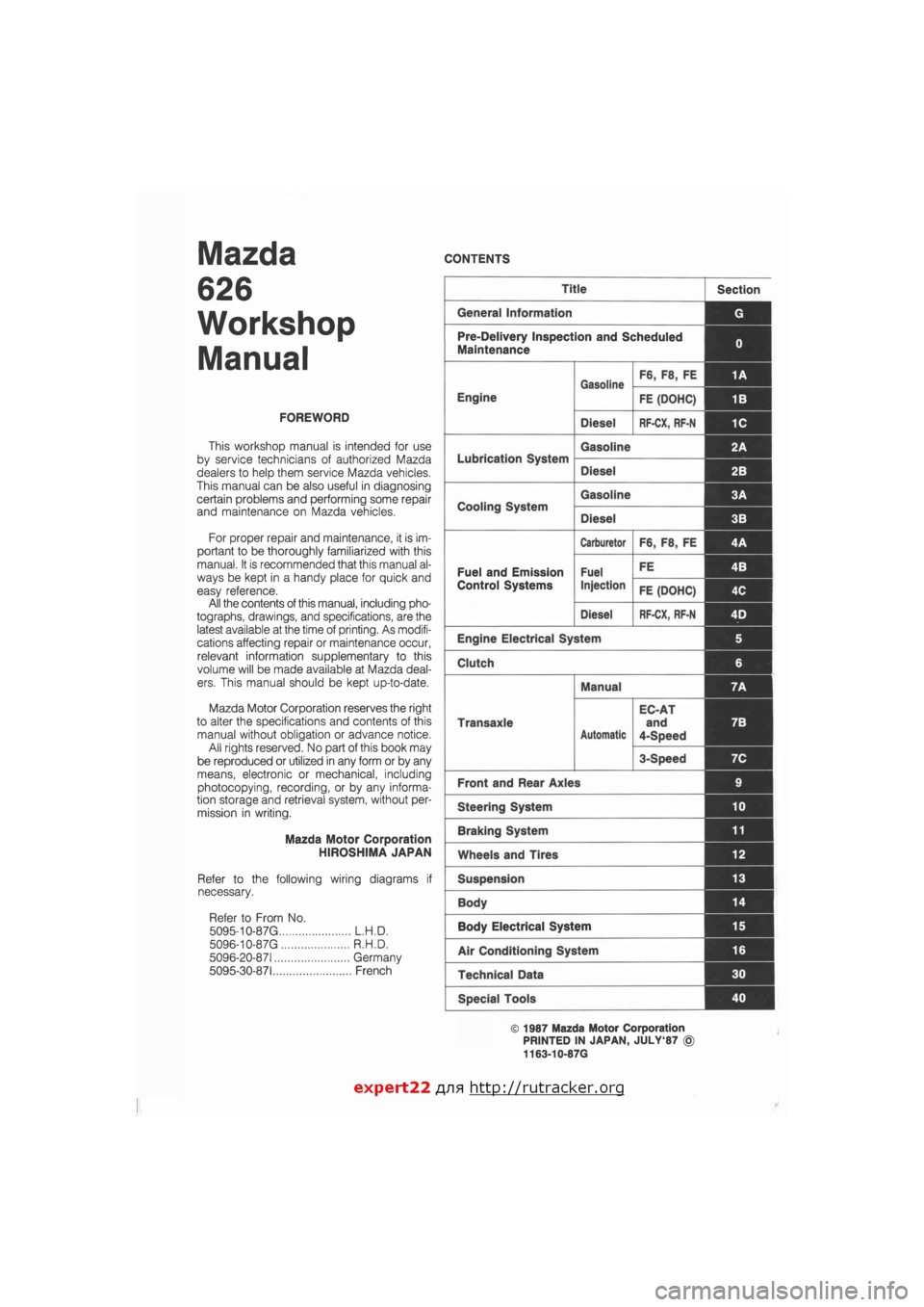
CONTENTS
Title Section
General Information G
Pre-Delivery Inspection and Scheduled
Maintenance 0
Gasoline F6, F8, FE 1A
Engine
Gasoline
FE (DOHC) 1B
Diesel RF-CX, RF-N 1C
Lubrication System
Gasoline 2A
Lubrication System
Diesel 2B I
Cooling System
Gasoline 3A 1
Cooling System
Diesel 3B
Carburetor F6, F8, FE 4A
Fuel and Emission Fuel FE 4B I
Control Systems Injection FE (DOHC) 4C
Diesel RF-CX, RF-N 4D j
Engine Electrical System 5
Clutch 6
Manual 7A
Transaxle
Automatic
EC-AT
and
4-Speed
7B
3-Speed 7C
Front and Rear Axles 9
Steering System 10
Braking System 11
Wheels and Tires 12
Suspension 13
Body 14 |
Body Electrical System 15
Air Conditioning System 16
Technical Data 30
Special Tools 40
© 1987 Mazda Motor Corporation
PRINTED IN JAPAN, JULY'87 ©
1163-10-87G
expert22 flna http://rutracker.org
Page 13 of 1865

PRE-DELIVERY INSPECTION
AND
SCHEDULED MAINTENANCE
SERVICES
PRE-DELIVERY INSPECTION 0— 2
PRE-DELIVERY INSPECTION TABLE 0— 2
SCHEDULED MAINTENANCE SERVICES .... 0— 3
MAINTENANCE TABLE
(For ECE Leaded gasoline) 0— 3
MAINTENANCE TABLE
(For ECE Unleaded gasoline) 0— 9
MAINTENANCE TABLE (For General) 0—15
76G00X-001
Page 522 of 1865

4B FUEL SYSTEM
Pressure Regulator
1. Disconnect the vacuum hose and fuel return hose.
2. Remove the pressure regulator.
3. Install in the reverse order of removal.
Tightening torque:
8—11 N-m (0.8—1.1 m-kg, 69—95 in-lb)
76G04B-084
Pulsation Damper
1. Loosen the pulsation damper and remove it.
2. Install in the reverse order of removal.
76G04B-085
^-Fuel hose
ML*? ^-Fuel pump
^silntank filter
ti* e
76G04B-086
h
tS
Is o
Sjfbj
Fuel Filter
Low pressure side
Refer to page 4B—57.
86U04A-116
High pressure side
The fuel filter must be replaced at the intervals out-
lined in the maintenance schedule.
Warning
Always work away from sparks or open
flames.
1. Disconnect the fuel hoses from the fuel filter.
2. Remove the fuel filter and the bracket.
3. Install a new filter and the bracket.
4. Connect the fuel hoses.
Note
When installing the filter, push the fuel hoses
fully onto the fuel filter and secure the hoses
with spring clamps.
4B-60
Page 594 of 1865

INTAKE AIR SYSTEM 4C
76G04C-054
76G04C-055
76G04C-056
Removal Note
Water hose
Before disconnecting the water hose, drain two liters
of engine coolant.
Delivery pipe assembly.
1. Separate the fuel return pipe from the delivery pipe
assembly.
2. Remove the delivery pipe assembly and the fuel
return pipe.
PARTS INSPECTION
Air Cleaner Element
1. Check the condition of the air cleaner element.
2. Blow out the dust with compressed air, if
necessary.
Caution
a) The air cleaner must be replaced at the in-
tervals outlined in the maintenance
schedule.
b) Never drive the vehicle without the air
cleaner element, otherwise, damage to the
air flow sensor (hot wire) will occur.
c) Never use an oil permeated air cleaner ele-
ment, otherwise, contamination of the hot
wire will occur.
4C—33
Page 625 of 1865

4C FUEL SYSTEM
^ Pulsation
damper
76G04C-121
Pulsation damper
—
Delivery pipe
76G04C-122
Fuel hose
,Fuel pump
-Intank filter
76G04C-123
Insulator
f f r—
/ 0 DM
•
II r
O - ring
Grommet
Manifold
Delivery pipe
Pressure Regulator
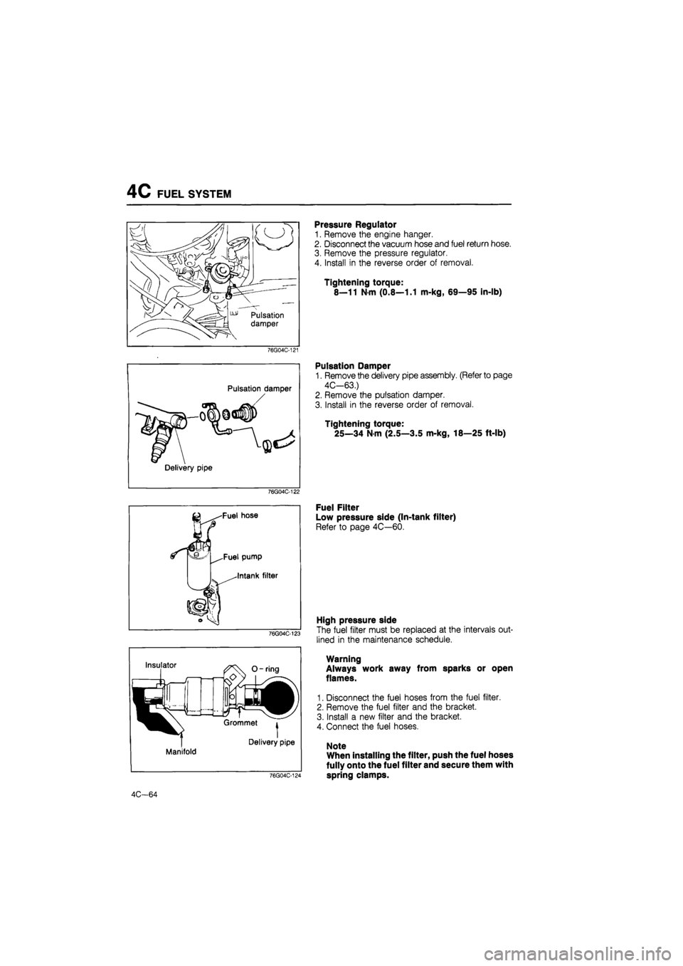
1. Remove the engine hanger.
2. Disconnect the vacuum hose and fuel return hose.
3. Remove the pressure regulator.
4. Install in the reverse order of removal.
Tightening torque:
8—11 Nm (0.8—1.1 m-kg, 69—95 in-lb)
Pulsation Damper
1. Remove the delivery pipe assembly. (Refer to page
4C-63.)
2. Remove the pulsation damper.
3. Install in the reverse order of removal.
Tightening torque:
25—34 N m (2.5—3.5 m-kg, 18—25 ft-lb)
Fuel Filter
Low pressure side (In-tank filter)
Refer to page 4C—60.
76G04C-124
High pressure side
The fuel filter must be replaced at the intervals out-
lined in the maintenance schedule.
Warning
Always work away from sparks or open
flames.
1. Disconnect the fuel hoses from the fuel filter.
2. Remove the fuel filter and the bracket.
3. Install a new filter and the bracket.
4. Connect the fuel hoses.
Note
When installing the filter, push the fuel hoses
fully onto the fuel filter and secure them with
spring clamps.
4C-64