recommended oil MAZDA 626 1987 Workshop Manual
[x] Cancel search | Manufacturer: MAZDA, Model Year: 1987, Model line: 626, Model: MAZDA 626 1987Pages: 1865, PDF Size: 94.35 MB
Page 15 of 1865
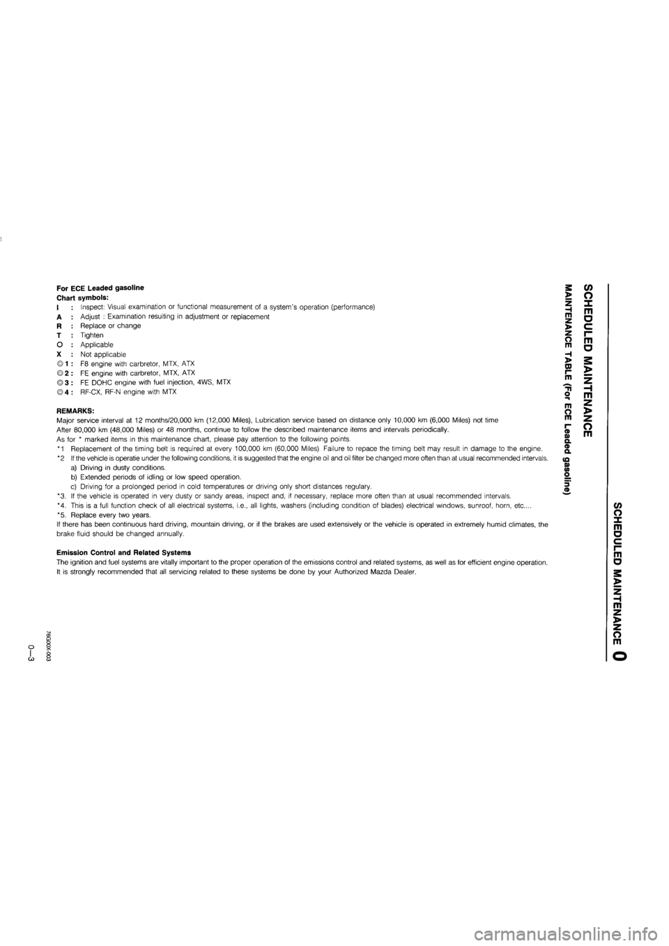
For ECE Leaded gasoline
Chart symbols:
I
A
R
T
O
X
Inspect: Visual examination or functional measurement of a system's operation (performance)
Adjust : Examination resulting in adjustment or replacement
Replace or change
Tighten
Applicable
Not applicable
F8 engine with carbretor, MTX, ATX
FE engine with carbretor, MTX, ATX
FE DOHC engine with fuel injection, 4WS, MTX
RF-CX, RF-N engine with MTX
REMARKS:
Major service interval at 12 months/20,000 km (12,000 Miles), Lubrication service based on distance only 10,000 km (6,000 Miles) not time
After 80,000 km (48,000 Miles) or 48 months, continue to follow the described maintenance items and intervals periodically.
As for * marked items in this maintenance chart, please pay attention to the following points.
*1 Replacement of the timing belt is required at every 100,000 km (60,000 Miles). Failure to repace the timing belt may result in damage to the engine.
*2 If the vehicle is operatie under the following conditions, it is suggested that the engine oil and oil filter be changed more often than at usual recommended intervals.
a) Driving in dusty conditions.
b) Extended periods of idling or low speed operation.
c) Driving for a prolonged period in cold temperatures or driving only short distances regulary.
*3. If the vehicle is operated in very dusty or sandy areas, inspect and, if necessary, replace more often than at usual recommended intervals.
*4. This is a full function check of all electrical systems, i.e., all lights, washers (including condition of blades) electrical windows, sunroof, horn, etc....
*5. Replace every two years.
If there has been continuous hard driving, mountain driving, or if the brakes are used extensively or the vehicle is operated in extremely humid climates, the
brake fluid should be changed annually.
>
Z H m >
o m
H >
CD r-m
o m
m O m
(D o> Q. ® a
(Q 0) <0 o
m a
o m
c/> o x m a
Emission Control and Related Systems
The ignition and fuel systems are vitally important to the proper operation of the emissions control and related systems, as well as for efficient engine operation.
It is strongly recommended that all servicing related to these systems be done by your Authorized Mazda Dealer.
m a
m z >
z o m
G)
Page 21 of 1865
r
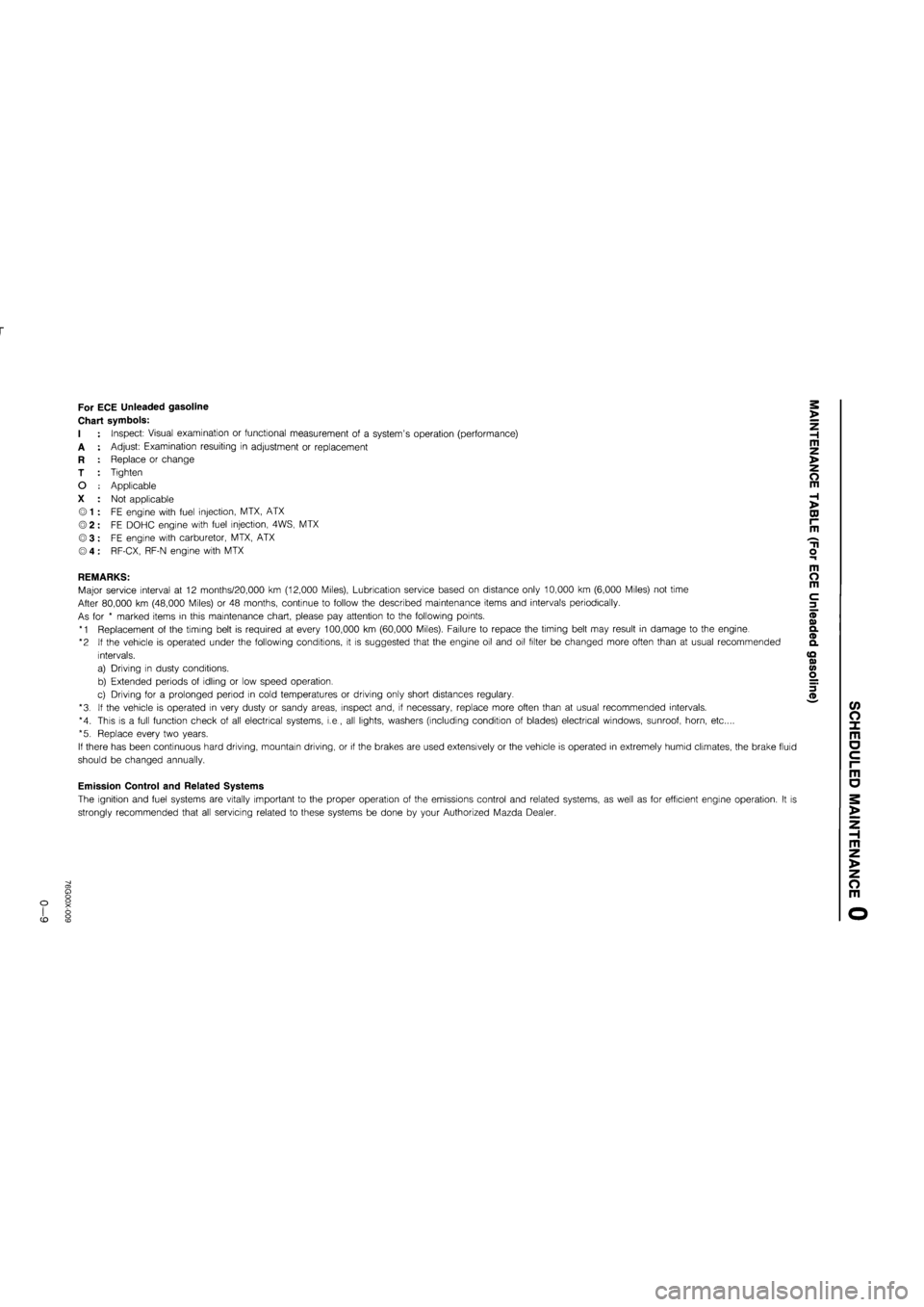
For ECE Unleaded gasoline
Chart symbols:
I
A
R
T
O
X
Inspect: Visual examination or functional measurement of a system's operation (performance)
Adjust: Examination resulting in adjustment or replacement
Replace or change
Tighten
Applicable
Not applicable
FE engine with fuel injection, MTX, ATX
FE DOHC engine with fuel injection, 4WS, MTX
FE engine with carburetor, MTX, ATX
RF-CX, RF-N engine with MTX
REMARKS:
Major service interval at 12 months/20,000 km (12,000 Miles), Lubrication service based on distance only 10,000 km (6,000 Miles) not time
After 80,000 km (48,000 Miles) or 48 months, continue to follow the described maintenance items and intervals periodically.
As for * marked items in this maintenance chart, please pay attention to the following points.
*1 Replacement of the timing belt is required at every 100,000 km (60,000 Miles). Failure to repace the timing belt may result in damage to the engine.
*2 If the vehicle is operated under the following conditions, it is suggested that the engine oil and oil filter be changed more often than at usual recommended
intervals.
a) Driving in dusty conditions.
b) Extended periods of idling or low speed operation.
c) Driving for a prolonged period in cold temperatures or driving only short distances regulary.
*3. If the vehicle is operated in very dusty or sandy areas, inspect and, if necessary, replace more often than at usual recommended intervals.
*4. This is a full function check of all electrical systems, i.e., all lights, washers (including condition of blades) electrical windows, sunroof, horn, etc....
*5. Replace every two years.
If there has been continuous hard driving, mountain driving, or if the brakes are used extensively or the vehicle is operated in extremely humid climates, the brake fluid
should be changed annually.
Emission Control and Related Systems
The ignition and fuel systems are vitally important to the proper operation of the emissions control and related systems, as well as for efficient engine operation. It is
strongly recommended that all servicing related to these systems be done by your Authorized Mazda Dealer.
>
Z H m z >
o m
H >
DJ r~ m
m o m
c 3
(/> O X m o c i-m
o
m z >
z o m
CD
Page 27 of 1865
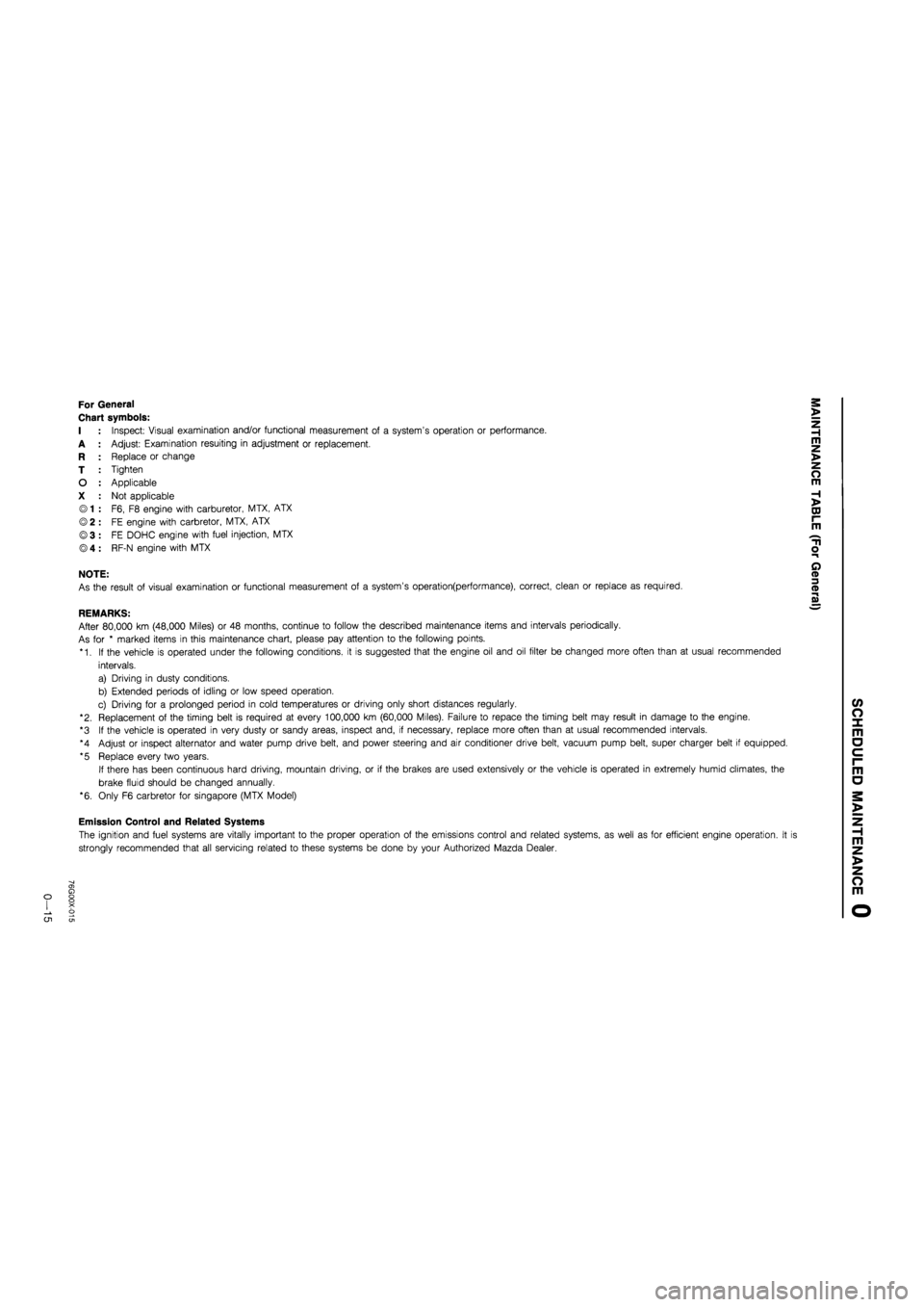
For General
Chart symbols:
I : Inspect: Visual examination and/or functional measurement of a system's operation or performance.
A : Adjust: Examination resuiting in adjustment or replacement.
R : Replace or change
T : Tighten
O : Applicable
X : Not applicable
© 1 : F6, F8 engine with carburetor, MTX, ATX
© 2 : FE engine with carbretor, MTX, ATX
©3 : FE DOHC engine with fuel injection, MTX
® 4 : RF-N engine with MTX
NOTE:
As the result of visual examination or functional measurement of a system's operation(performance), correct, clean or replace as required.
REMARKS:
After 80,000 km (48,000 Miles) or 48 months, continue to follow the described maintenance items and intervals periodically.
As for * marked items in this maintenance chart, please pay attention to the following points.
*1. If the vehicle is operated under the following conditions, it is suggested that the engine oil and oil filter be changed more often than at usual recommended
intervals.
a) Driving in dusty conditions.
b) Extended periods of idling or low speed operation.
c) Driving for a prolonged period in cold temperatures or driving only short distances regularly.
"2. Replacement of the timing belt is required at every 100,000 km (60,000 Miles). Failure to repace the timing belt may result in damage to the engine.
*3 If the vehicle is operated in very dusty or sandy areas, inspect and, if necessary, replace more often than at usual recommended intervals.
*4 Adjust or inspect alternator and water pump drive belt, and power steering and air conditioner drive belt, vacuum pump belt, super charger belt if equipped.
*5 Replace every two years.
If there has been continuous hard driving, mountain driving, or if the brakes are used extensively or the vehicle is operated in extremely humid climates, the
brake fluid should be changed annually.
*6. Only F6 carbretor for Singapore (MTX Model)
Emission Control and Related Systems
The ignition and fuel systems are vitally important to the proper operation of the emissions control and related systems, as well as for efficient engine operation. It i
strongly recommended that all servicing related to these systems be done by your Authorized Mazda Dealer.
o CJ1
Page 30 of 1865
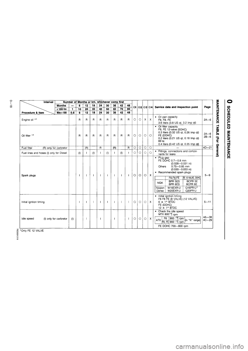
Interval
Procedure & item
Number of Months or km, whichever corns first
Months
x 1000 Km
Miles x 1000
Engine oil
Oil filter
Fuel filter (R) only for carbretor
Fuel lines and hoses (I) only for Diesel
Spark plugs
Initial ignition timing
Idle speed (I) only for carbretor
0.6
(I)
6
10
(0
12
20
12
(R)
18
30
18
(I)
24
40
24
30
50
30
(I)
36
60
36
(R)
42
70
42
(I)
48
80
48
®1
O
o
o
o
o
o
o
©2
O
o
o
o
o
o
o
©3
O
o
o
o
o
o
©4
O
o
o
Service data and inspection point
Oil pan capacity F6, F8, FE 3.6 liters (3.8 US qt, 3.2 Imp qt)
Oil filter capacity F8, FE 12-valve (SOHC)
0.3 liters (0.32 US qt, 0.26 Imp qt)
FE (DOHC) 0.2 liters (0.21 US qt, 0.18 Imp qt) RF-N
0.4 liters (0.42 US qt, 0.35 Imp qt)
Fittings, connections and compo-
nents for leaks
Plug gap FE DOHC 0.7—0.8 mm (0.028-0.031 in) Others 0.75—0.85 mm (0.030—0.033 in) Recommended spark plugs
F6,F8,FE FE
12 VALVE,
DOHC
NGK BPR 5ES BPR 6ES BCPR 5E
BCPR 6E
Nippon
Denso W16EXR-U
W20EXR-U
Q16PR-U* Q20PR-U
Initial ignition timing F6 F8 FE (8 VALVE) (12 VALVE)
6 ±
1
° BTDC FE (DOHC) 12 ± 1° BTDC
Check the idle speed
MTX 80015? rpm
ATX F6 900 rpm (in "N" range) ATX F8, FE 900 t5? rpm (in "N" range)
FE DOHC 700—800 rpm
§ *Only FE 12 VALVE
Page
2A—6
2A-6
2B-6
4D—21
5-9
5-11
4A—38
4C-29
m z >
z o m
H >
CD I-m
T1
o
o
m z >
z o m
Page 315 of 1865
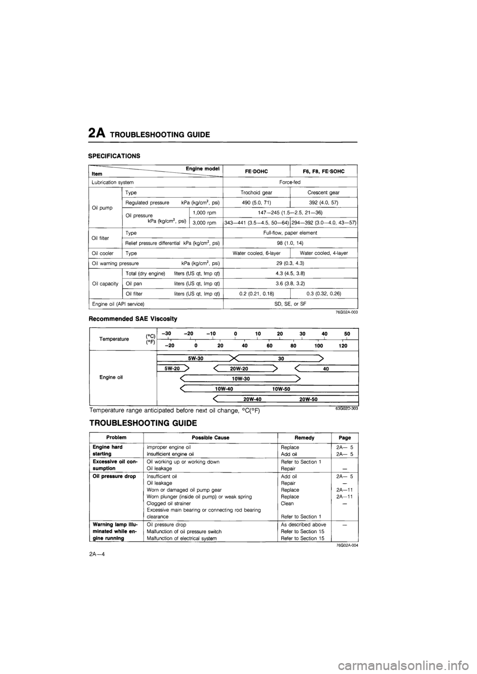
2 A TROUBLESHOOTING GUIDE
SPECIFICATIONS
Engine model Item . FEDOHC F6, F8, FE SOHC
Lubrication system Force-fed
Oil pump
Type Trochoid gear Crescent gear
Oil pump Regulated pressure kPa (kg/cm2, psi) 490 (5.0, 71) 392 (4.0, 57) Oil pump
Oil pressure kPa (kg/cm2, psi)
1,000 rpm 147-245 (1.5-2.5, 21-36) Oil pump
Oil pressure kPa (kg/cm2, psi) 3,000 rpm 343—441 (3.5-4.5, 50-64) 294-392 (3.0-4.0, 43—57)
Oil filter Type Full-flow, paper element Oil filter Relief pressure differential kPa (kg/cm2, psi) 98 (1.0, 14)
Oil cooler Type Water cooled, 6-layer Water cooled, 4-layer
Oil warning pressure kPa (kg/cm2, psi) 29 (0.3, 4.3)
Oil capacity
Total (dry engine) liters (US qt, Imp qt) 4.3 (4.5, 3.8)
Oil capacity Oil pan liters (US qt, Imp qt) 3.6 (3.8, 3.2) Oil capacity
Oil filter liters (US qt, Imp qt) 0.2 (0.21, 0.18) 0.3 (0.32, 0.26)
Engine oil (API service) SD, SE, or SF
76G02A-003
Recommended SAE Viscosity
Temperature j0pj
-30 -20 -10 0 10 20 30 40 50 I l I I 1 < ! I I Temperature j0pj i i i i I i 1 1
-20 0 20 40 60 80 100 120
Engine oil Engine oil
5W-30 X 30 >
Engine oil Engine oil
5W-20 > < 20W-20 > < 40
Engine oil < 10W-30 > Engine oil
< 10W-40 10W-50
Engine oil Engine oil
< 20W-40 20W-50
Engine oil
Temperature range anticipated before next oil change, °C(°F)
TROUBLESHOOTING GUIDE
Problem Possible Cause Remedy Page
Engine hard
starting
Improper engine oil
Insufficient engine oil
Replace
Add oil
2A— 5
2A— 5
Excessive oil con-
sumption
Oil working up or working down
Oil leakage
Refer to Section 1
Repair
Oil pressure drop Insufficient oil
Oil leakage
Worn or damaged oil pump gear
Worn plunger (inside oil pump) or weak spring
Clogged oil strainer
Excessive main bearing or connecting rod bearing
clearance
Add oil
Repair
Replace
Replace
Clean
Refer to Section 1
2A- 5
2A-11
2A-11
Warning lamp illu-
minated while en-
gine running
Oil pressure drop
Malfunction of oil pressure switch
Malfunction of electrical system
As described above
Refer to Section 15
Refer to Section 15
76G02A-004
2A—4
Page 327 of 1865
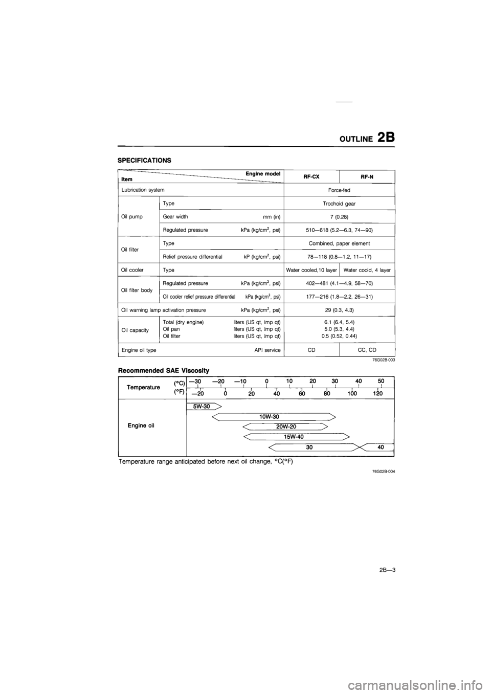
OUTLINE 2B
SPECIFICATIONS
Item Engine model RF-CX RF-N
Lubrication system Force-fed
Type Trochoid gear
Oil pump Gear width mm (in) 7 (0.28)
Regulated pressure kPa (kg/cm2,
psi)
510-618 (5.2 -6.3, 74—90)
Oil filter
Type Combined, paper element
Oil filter
Relief pressure differential kP (kg/cm2,
psi)
78-118 (0.8--1.2, 11-17)
Oil cooler Type Water cooled, 10 layer Water coold,
4
layer
Oil filter body
Regulated pressure kPa (kg/cm2,
psi)
402—481
(4.1
-4.9, 58—70)
Oil filter body
Oil cooler relief pressure differential kPa (kg/cm2, psi) 177-216 (1.8 -2.2, 26-31)
Oil warning lamp activation pressure kPa (kg/cm2,
psi)
29 (0.3, 4.3)
Oil capacity
Total (dry engine)
Oil pan
Oil filter
liters (US qt, Imp
qt)
liters (US qt, Imp
qt)
liters (US qt, Imp
qt)
6.1 (6.4, 5.4)
5.0 (5.3, 4.4)
0.5 (0.52, 0.44)
Engine oil type API service CD CC,
CD
76G02B-003
Recommended SAE Viscosity
CC) Temperature
—30 —20 —10 0 10 20 30 40 50 i i i i i i i ii CC) Temperature i i II i i i i —20 0 20 40 60 80 100 120
Engine oil
5W-30 >
Engine oil
< 10W-30 >
< 20W-20 >
< 15W-40 >
Engine oil
Temperature range anticipated before next oil change, °C(°F)
76G02B-004
2B-3
Page 907 of 1865

TROUBLESHOOTING (G4A-HL) 7B
TROUBLESHOOTING (G4A-HL)
GENERAL NOTE
In the event of a problem with the automatic transaxle, the cause may be in the engine, power train,
hydraulic control system, or electrical control system.
When troubleshooting, therefore, it is recommended to begin from those points that can be judged
quickly and easily. The recommended troubleshooting sequence is described below.
STEP 4: TIME LAG TEST
Check time lag of oil pressure supply
STEP 6: OIL PRESSURE TEST Check line, throttle, and governor pressures
This step checks conditions surrounding the automatic
transaxle.
This step checks the electrical control system.
• Function of the electrical control system
• Components
This step checks the power train. • Friction element slipping • Torque converter capacity
This step checks operation of the hydraulic control system. • Accumulators • Friction elements slipping • Regulating valves
This step checks functions of the electric control system and
hydraulic control system.
This step checks major points of the hydraulic control system.
• Oil pump • Line pressure control • Throttle pressure control
• Governer pressure control
STEP 5: ROAD TEST Check items on road test
• Shift point • Shift schedule
• Kick-down • Shift shock • Lock-up and overdrive inhibition
By following the above 6 steps, the cause of the problem should be located.
As another guide to faster location of the causes of problems, the Quick Diagnosis Chart is included
at pages 7B—42, 43.
In this chart, a circle is used to indicate the components that might be the cause of trouble for 20
types of problems. It is only necessary to check those components indicated by circles, at each step
of the troubleshooting process, in order to quickly locate the cause of the problem.
76G07B-040
7B—41
Page 1122 of 1865
7C TROUBLESHOOTING
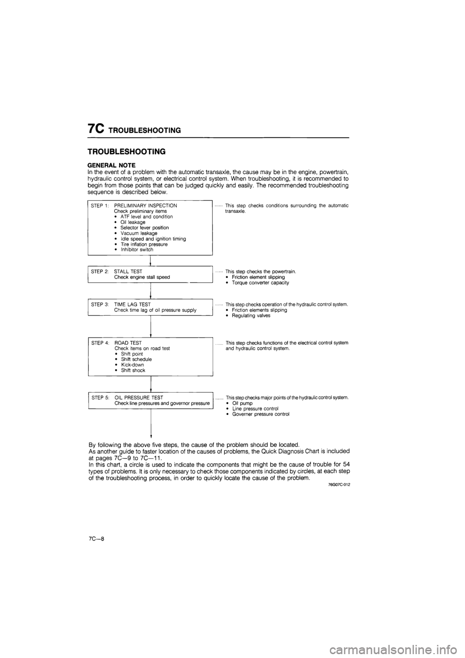
TROUBLESHOOTING
GENERAL NOTE
In the event of a problem with the automatic transaxle, the cause may be in the engine, powertrain,
hydraulic control system, or electrical control system. When troubleshooting, it is recommended to
begin from those points that can be judged quickly and easily. The recommended troubleshooting
sequence is described below.
STEP 1: PRELIMINARY INSPECTION Check preliminary items • ATF level and condition
• Oil leakage • Selector lever position
• Vacuum leakage
• Idle speed and ignition timing
• Tire inflation pressure • Inhibitor switch
This step checks conditions surrounding the automatic
transaxle.
STEP 2: STALL TEST Check engine stall speed This step checks the powertrain.
• Friction element slipping
• Torque converter capacity
STEP 3: TIME LAG TEST Check time lag of oil pressure supply This step checks operation of the hydraulic control system. • Friction elements slipping
• Regulating valves
STEP 4: ROAD TEST Check items on road test
• Shift point • Shift schedule
• Kick-down • Shift shock
This step checks functions of the electrical control system
and hydraulic control system.
STEP 5: OIL PRESSURE TEST Check line pressures and governor pressure This step checks major points of the hydraulic control system.
• Oil pump • Line pressure control • Governer pressure control
By following the above five steps, the cause of the problem should be located.
As another guide to faster location of the causes of problems, the Quick Diagnosis Chart is included
at pages 7C—9 to 7C—11.
In this chart, a circle is used to indicate the components that might be the cause of trouble for 54
types of problems. It is only necessary to check those components indicated by circles, at each step
of the troubleshooting process, in order to quickly locate the cause of the problem.
76G07C-012
7C—8