lock MAZDA MIATA 1991 Factory Service Manual
[x] Cancel search | Manufacturer: MAZDA, Model Year: 1991, Model line: MIATA, Model: MAZDA MIATA 1991Pages: 392, PDF Size: 29.45 MB
Page 319 of 392
ANTI-LOCK BRAKE SYSTEM
The anti-lock brake system contains electronic equipment that can be susceptible to interference caused by
improperly installed or high output radio transmitting equipment. Since this interference could cause the
possible loss of the anti-lock braking capability, such equipment should be installed by qualified professionals.
On models equipped with anti-lock brake systems, ALWAYS observe the following cautions:
DO NOT attempt to bleed hydraulic system without first referring to the appropriate ANTI-LOCK
BRAKE SYSTEM article in the BRAKES Section.
DO NOT mix tire sizes. As long as tires remain close to the original diameter, increasing the width is
acceptable. Rolling diameter must be identical for all 4 tires. Some manufacturers recommend tires of the
same brand, style and type. Failure to follow this precaution may cause inaccurate wheel speed readings.
Use ONLY recommended brake fluids. DO NOT use silicone brake fluids in an ABS-equipped vehicle.
BATTERY WARNING
REPLACING BLOWN FUSES
Before replacing a blown fuse, remove ignition key, turn off all lights and accessories to avoid damaging the
electrical system. Be sure to use fuse with the correct indicated amperage rating. The use of an incorrect
amperage rating fuse may result in a dangerous electrical system overload.
BRAKE PAD WEAR INDICATOR
Indicator will cause a squealing or scraping noise, warning that brake pads need replacement.
CATALYTIC CONVERTER
Continued operation of vehicle with a severe malfunction could cause converter to overheat, resulting in
possible damage to converter and vehicle. service.
WARNING:R-134a service equipment or vehicle A/C systems SHOULD NOT be
pressure tested or leak tested with compressed air. Some mixtures of
air/R134a have shown to be combustible at elevated pressures. These
mixtures are dangerous and may cause fire and/or explosions. See AIR
CONDITIONING SERVICE article in GENERAL INFORMATION section.
WARNING:When battery is disconnected, vehicles equipped with computers may
lose memory data. When battery power is restored, driveability problems
may exist on some vehicles. These vehicles may require a relearn
procedure. See COMPUTER RELEARN PROCEDURES article in GENERAL
INFORMATION section.
1991 Mazda MX-5 Miata
FUSES & CIRCUIT BREAKERS Fuses & Circuit Breakers 1990-95 Mazda
Microsoft
Sunday, July 05, 2009 2:15:54 PMPage 6 © 2005 Mitchell Repair Information Company, LLC.
Page 329 of 392

3. If battery voltage is present, turn off blower switch and A/C switch (if equipped). Check voltage at
Blue/Red wire terminal of blower resistor 1-wire connector. If no voltage is present, replace blower
motor. If battery voltage is present, check voltage at Blue/White wire terminal of blower resistor
connector.
4. If no voltage is present, replace blower resistor. If battery voltage is present, check voltage at Blue/Red
wire terminal of blower resistor 4-wire connector. If no voltage is present, replace blower resistor.
5. If battery voltage is present, check voltage at Blue/Green wire terminal of blower resistor connector. If no
voltage is present, replace blower resistor. If battery voltage is present, check voltage at Blue/Yellow wire
terminal of blower resistor connector.
6. If no voltage is present, replace blower resistor. If battery voltage is present, turn ignition on and blower
switch to 4th position (high). Check voltage at Black wire terminal of blower switch connector. If battery
voltage is present, repair wiring between blower switch and ground.
7. If no voltage is present, turn ignition switch, blower switch and A/C switch off. Check voltage at
Blue/White wire terminal of blower switch connector. If no voltage is present, repair wiring between
blower resistor and blower switch.
8. If battery voltage is present, check voltage at Blue/Red wire terminal of blower switch connector. If no
voltage is present, repair wiring between blower resistor and blower switch. If battery voltage is present,
check voltage at Blue/Green wire terminal of blower switch connector.
9. If no voltage is present, repair wiring between blower resistor and blower switch. If battery voltage is
present, check voltage at Blue/Yellow wire terminal of blower switch connector. If battery voltage is
present, replace blower switch. If no voltage is present, repair wiring between blower resistor and blower
switch.
COMPRESSOR CLUTCH CIRCUIT
1. Turn ignition on. Check 20-amp WIPER fuse in passenger compartment fuse block. Check 20-amp AD
FAN (additional fan) fuse in engine compartment fuse block. If fuses are blown, repair short circuit.
2. If fuses are okay, run engine at idle. Turn A/C and blower switches on. Check voltage at compressor
clutch connector (Black/Red wire terminal). If no voltage is present, go to step 5).
3. If battery voltage is present, turn ignition off. Disconnect evaporator thermoswitch connector. Check
continuity between switch terminals. If there is no continuity, replace evaporator thermoswitch.
4. If there is continuity, disconnect compressor clutch connector. Set ohmmeter to X1000 scale. Check
continuity between compressor clutch connector and ground. If there is no continuity, replace compressor
clutch. If there is continuity, adjust compressor clutch air gap or check compressor for internal damage.
5. Run engine at idle. Turn A/C and blower switches on. Check voltage at Black/Blue wire terminal of A/C
relay connector. If battery voltage is present, go to step 9).
6. If no voltage is present, check voltage at Blue/Yellow wire terminal of A/C relay connector. If no voltage
is present, repair circuit between 20-amp AD FAN fuse and A/C relay.
7. If battery voltage is present, check voltage at Blue wire terminal of A/C relay connector. If no voltage is
present, repair circuit between 20-amp WIPER fuse and A/C rela
y. NOTE: Blower resistor uses a 1-wire connector and a 4-wire connector. The wire
in the 1-wire connector is Blue/Red, and one of the wires in the 4-wire
connector is Blue/Red. Check voltage at appropriate wire.
1991 Mazda MX-5 Miata
A/C-HEATER SYSTEM - MANUAL 1990-92 Manual A/C-Heater Systems
Microsoft
Sunday, July 05, 2009 2:11:52 PMPage 3 © 2005 Mitchell Repair Information Company, LLC.
Page 338 of 392
STEERING GEAR - POWER RACK & PINION
1991 STEERING Mazda - Power Rack & Pinion
DESCRIPTION
Steering system is a power-assisted rack and pinion. The system consists of a rack and pinion steering gear and
power-assist pump/reservoir. The steering gear and pump/reservoir are connected by flexible hoses.
TESTING
HYDRAULIC SYSTEM PRESSURE TEST
Pump Fluid Pressure Test
1. Disconnect pressure hose and connect pressure gauge/valve between steering pump and steering gear. See
Fig. 1
. Bleed air from system.
2. Open valve fully. Start engine and idle. Turn steering wheel lock-to-lock to increase fluid temperature to
122-140°F (50-60°C). To measure pump fluid pressure, close gauge valve completely.
3. Increase engine speed to 1000-1500 RPM. Ensure pump pressure is within specification. See
HYDRAULIC SYSTEM FLUID PRESSURE SPECIFICATIONS
table. If pressure is not within
specification, replace pump.
CAUTION: DO NOT leave gauge valve closed for more than 15 seconds, or pump may
be damaged.
1991 Mazda MX-5 Miata
STEERING GEAR - POWER RACK & PINION 1991 STEERING Mazda - Power Rack & Pinion
1991 Mazda MX-5 Miata
STEERING GEAR - POWER RACK & PINION 1991 STEERING Mazda - Power Rack & Pinion
Microsoft
Sunday, July 05, 2009 2:10:15 PMPage 1 © 2005 Mitchell Repair Information Company, LLC.
Microsoft
Sunday, July 05, 2009 2:10:19 PMPage 1 © 2005 Mitchell Repair Information Company, LLC.
Page 339 of 392
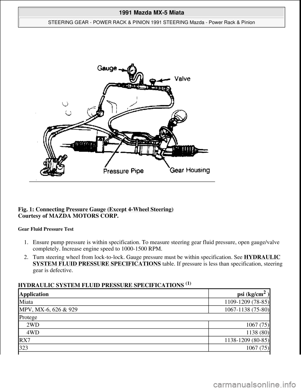
Fig. 1: Connecting Pressure Gauge (Except 4-Wheel Steering)
Courtesy of MAZDA MOTORS CORP.
Gear Fluid Pressure Test
1. Ensure pump pressure is within specification. To measure steering gear fluid pressure, open gauge/valve
completely. Increase engine speed to 1000-1500 RPM.
2. Turn steering wheel from lock-to-lock. Gauge pressure must be within specification. See HYDRAULIC
SYSTEM FLUID PRESSURE SPECIFICATIONStable. If pressure is less than specification, steering
gear is defective.
HYDRAULIC SYSTEM FLUID PRESSURE SPECIFICATIONS
(1)
Applicationpsi (kg/cm2 )
Miata1109-1209 (78-85)
MPV, MX-6, 626 & 9291067-1138 (75-80)
Protege
2WD1067 (75)
4WD1138 (80)
RX71138-1209 (80-85)
3231067 (75)
1991 Mazda MX-5 Miata
STEERING GEAR - POWER RACK & PINION 1991 STEERING Mazda - Power Rack & Pinion
Microsoft
Sunday, July 05, 2009 2:10:15 PMPage 2 © 2005 Mitchell Repair Information Company, LLC.
Page 340 of 392
LUBRICATION
CAPACITY
POWER STEERING FLUID CAPACITY
FLUID TYPE
Dexron-II or M-III are recommended for all vehicles.
FLUID LEVEL CHECK
Check fluid level with engine off. Remove fluid level gauge on oil pump or reservoir. Check fluid level. Fluid
should be between "L" and "H" marks on level gauge dipstick. If fluid level is low, fill through gauge tube.
Recheck fluid level. DO NOT overfill.
HYDRAULIC FLUID BLEEDING
1. Raise and support front of vehicle. With ignition off, turn steering wheel lock-to-lock several times. Add
fluid as necessary. Repeat procedure until fluid level no longer decreases.
2. Start engine and let idle. Turn steering wheel lock-to-lock 5 times. Check fluid level. Add fluid as
necessary. Continue procedure until fluid is clear of air bubbles and does not decrease in level.
ADJUSTMENTS
POWER STEERING BELT ADJUSTMENT
POWER STEERING BELT DEFLECTION
(1)
(1)Specifications are measured at 1000-1500 RPM, with fluid temperature at 122-140°F (50-60°C).
ApplicationQts. (L)
Miata, MPV & 929.95 (.90)
MX-6 & 626
Electronc Controlled Power Steering (ECPS)1.06 (1.0)
Engine Speed (Sensing) Power Steering (ESPS).95 (.90)
Protege & 323.63 (.60)
RX7.85 (.80)
NOTE: On-vehicle adjustment procedures are not available from manufacturer.
ApplicationIn. (mm)
Miata, Protege & 323
New Belt.31-.35 (7.8-8.9)
1991 Mazda MX-5 Miata
STEERING GEAR - POWER RACK & PINION 1991 STEERING Mazda - Power Rack & Pinion
Microsoft
Sunday, July 05, 2009 2:10:15 PMPage 3 © 2005 Mitchell Repair Information Company, LLC.
Page 350 of 392

Fig. 8: Exploded View of Rack & Pinion Steering Gear (929)
Courtesy of MAZDA MOTORS CORP.
TORQUE SPECIFICATIONS
TORQUE SPECIFICATIONS
ApplicationFt. Lbs. (N.m)
Intermediate Shaft-To-Pinion Shaft Bolt
All Models Except RX713-19 (18-26)
RX712-18 (16-24)
Middle Crossmember
Front Bolt29-40 (39-54)
Rear Bolt58-86 (78-117)
Pinion Bearing Lock Nut29-36 (39-50)
Pinion Housing Lock Nut
Miata29-39 (39-53)
MPV, Protege & 32329-36 (39-50)
MX-6 & 62633-40 (44-54)
RX7 & 92936-51 (49-69)
Stabilizer Bar-To-Control Link Nut27-40 (36-54)
1991 Mazda MX-5 Miata
STEERING GEAR - POWER RACK & PINION 1991 STEERING Mazda - Power Rack & Pinion
Microsoft
Sunday, July 05, 2009 2:10:15 PMPage 13 © 2005 Mitchell Repair Information Company, LLC.
Page 352 of 392

SUSPENSION - REAR
1991 SUSPENSION Rear
DESCRIPTION
Rear suspension consists of MacPherson-type struts, crossmember, upper and lower arms and stabilizer bar with
control link. Upper and lower arms attach to crossmember and knuckle. A stabilizer bar with control link is
mounted to lower arm and crossmember. Rear wheel alignment is adjusted by turning adjusting cams on lower
arm.
ADJUSTMENTS & INSPECTION
WHEEL ALIGNMENT SPECIFICATIONS & PROCEDURES
See WHEEL ALIGNMENT SPECIFICATIONS AND PROCEDURES article in the WHEEL ALIGNMENT
section.
WHEEL BEARING
Raise vehicle and support. Remove wheel assembly. Remove caliper assembly and wire aside. Remove brake
rotor. Attach dial indicator to axle hub and measure bearing play. Maximum bearing play is .002" (.05 mm). If
play exceeds specification, check rear axle lock nut torque or replace wheel bearing.
REMOVAL & INSTALLATION
WHEEL BEARING
Removal
1. Raise and support vehicle. Remove wheel assembly. Remove drive axle lock nut. Remove brake caliper
assembly, and wire aside. Remove screws and rotor. Disconnect ABS speed sensor. Remove knuckle
assembly from upper and lower arms.
2. Using a press, Installer (49-G030-727) and Puller (49-F026-103), remove hub from knuckle. Remove
snap ring from knuckle. Using a press, installer and Puller (49-0636-145), remove wheel bearing inner
race from hub. Remove wheel bearing outer race from knuckle using a press and Adapter (49-F027-005).
Inspection
Check wheel hub and knuckle for cracks and damage. Check dust cover for deformation. Check bearing for
excessive wear or seizure.
Installation
Press new wheel bearing into knuckle using Installer (49-F027-007) and Adapter (49-F027-009). Press hub into
knuckle using installer. To install, reverse removal procedure. Tighten drive axle lock nut to specification. Stake
1991 Mazda MX-5 Miata
SUSPENSION - REAR 1991 SUSPENSION Rear
1991 Mazda MX-5 Miata
SUSPENSION - REAR 1991 SUSPENSION Rear
Microsoft
Sunday, July 05, 2009 2:09:35 PMPage 1 © 2005 Mitchell Repair Information Company, LLC.
Microsoft
Sunday, July 05, 2009 2:09:39 PMPage 1 © 2005 Mitchell Repair Information Company, LLC.
Page 353 of 392

drive axle lock nut. Check axial play. See WHEEL BEARING under ADJUSTMENTS & INSPECTION.
STRUT ASSEMBLY
Removal & Disassembly
1. Raise vehicle and remove fuel tank filler pipe protector. Remove rear wheel assembly. Remove stabilizer
bar nut and bolt. Remove 2 upper strut mount-to-body nuts. Remove lower strut bolt. Loosen upper and
lower arm bolts. Lower arms and remove strut assembly.
2. Clamp strut securely in soft-jawed vise. Compress coil spring. Remove lock nut and washer. Remove
remaining components and note order for reassembly.
Inspection
Check strut for leaks or abnormal noise. Inspect parts for wear or damage. Check for loose installation of bolts
and nuts. Replace parts as necessary.
Reassembly & Installation
To reassemble, reverse disassembly procedure. To install, reverse removal procedure. Ensure coil spring is well
seated in upper and lower seats. Check rear wheel toe-in. See SPECIFICATIONS & PROCEDURES article in
the WHEEL ALIGNMENT section.
LOWER ARM
Removal
Raise and support vehicle. Remove wheel assembly. Remove stabilizer bar control link nut and bolt. See Fig.
1 . Remove lower strut bolt. Remove lower arm-to-crossmember bolts. Remove lower arm-to-knuckle bolts.
Remove lower arm. Inspect arm for dama
ge, cracks and deformation. Check for damaged or worn bushings.
1991 Mazda MX-5 Miata
SUSPENSION - REAR 1991 SUSPENSION Rear
Microsoft
Sunday, July 05, 2009 2:09:35 PMPage 2 © 2005 Mitchell Repair Information Company, LLC.
Page 356 of 392

Installation
Inspect stabilizer bar and components for damage, cracks and deterioration. To install, reverse removal
procedure. Ensure bushing is aligned with White line on stabilizer. Ensure seam faces front of vehicle. Tighten
nuts and bolts to specification with vehicle resting on ground and suspension unloaded.
TORQUE SPECIFICATIONS
TORQUE SPECIFICATIONS
ApplicationFt. Lbs. (N.m)
ABS Speed Sensor Harness Bracket Bolts12-17 (16-23)
Caliper Assembly-To-Knuckle Bolt36-51 (49-69)
Control Link-To-Lower Arm Nut27-40 (36-54)
Lower Arm-To-Crossmember Nuts54-70 (73-95)
Lower Arm-To-Knuckle Nut46-55 (63-75)
Rear Axle Nut159-217 (216-294)
Stabilizer Bar Brackets Bolts15-21 (20-28)
Stabilizer Bar-To-Control Link Bolt27-40 (36-54)
Strut Piston Rod Lock Nut23-34 (31-46)
Strut-To-Body Nuts22-27 (29-36)
Strut-To-Lower Arm Bolt54-69 (73-93)
Upper Arm-To-Crossmember Nuts34-49 (46-67)
Upper Arm-To-Knuckle Bolt34-49 (46-67)
Wheel Lug Nuts65-87 (88-118)
1991 Mazda MX-5 Miata
SUSPENSION - REAR 1991 SUSPENSION Rear
Microsoft
Sunday, July 05, 2009 2:09:35 PMPage 5 © 2005 Mitchell Repair Information Company, LLC.
Page 357 of 392
STARTER - DIRECT DRIVE
1990-92 ELECTRICAL Mazda Starters - Direct Drive
DESCRIPTION
Nippondenso direct drive starter is a conventional 12-volt, 4-pole, brush-type starter. The integral solenoid is
attached to the drive housing. The overrunning clutch pinion drive is mounted directly on armature shaft drive
end.
TROUBLESHOOTING
TESTING (ON VEHICLE)
CIRCUIT TESTING
1. Turn ignition switch to START position, depress clutch and ensure starter operates. If starter does not
operate, use voltmeter to check voltage at "S" terminal when clutch is depressed and ignition is turned to
START position. See Fig. 1
.
2. If voltage is less than 8 volts, check starter interlock switch and ignition switch to starter wiring circuit for
short to ground. If voltage is greater than 8 volts and starter is inoperative, starter has an internal fault.
Repair or replace as required. NOTE: For information on B2200 and Protege models with automatic transmissions,
see STARTERS - GEAR REDUCTION article.
NOTE: See TROUBLE SHOOTING - BASIC PROCEDURES article in the GENERAL
INFORMATION section.
NOTE: Before testing, ensure battery is fully charged, battery cables and terminals are
clean and tight and engine grounds are good.
1991 Mazda MX-5 Miata
STARTER - DIRECT DRIVE 1990-92 ELECTRICAL Mazda Starters - Direct Drive
1991 Mazda MX-5 Miata
STARTER - DIRECT DRIVE 1990-92 ELECTRICAL Mazda Starters - Direct Drive
Microsoft
Sunday, July 05, 2009 2:13:20 PMPage 1 © 2005 Mitchell Repair Information Company, LLC.
Microsoft
Sunday, July 05, 2009 2:13:24 PMPage 1 © 2005 Mitchell Repair Information Company, LLC.