lock MAZDA MIATA 1991 Factory Repair Manual
[x] Cancel search | Manufacturer: MAZDA, Model Year: 1991, Model line: MIATA, Model: MAZDA MIATA 1991Pages: 392, PDF Size: 29.45 MB
Page 225 of 392
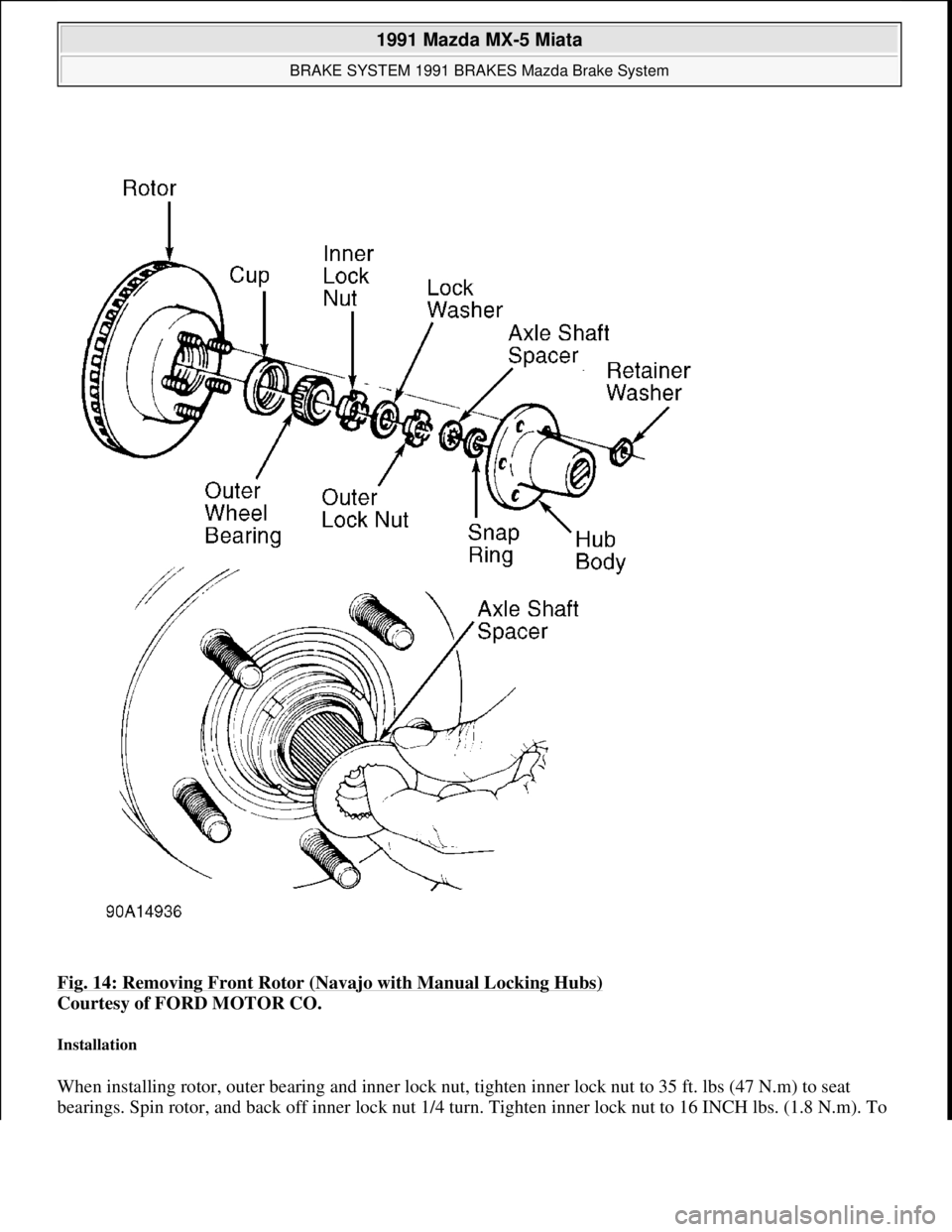
Fig. 14: Removing Front Rotor (Navajo with Manual Locking Hubs)
Courtesy of FORD MOTOR CO.
Installation
When installing rotor, outer bearing and inner lock nut, tighten inner lock nut to 35 ft. lbs (47 N.m) to seat
bearings. Spin rotor, and back off inner lock nut 1/4 turn. Tighten inner lock nut to 16 INCH lbs. (1.8 N.m). To
1991 Mazda MX-5 Miata
BRAKE SYSTEM 1991 BRAKES Mazda Brake System
Microsoft
Sunday, July 05, 2009 2:18:08 PMPage 22 © 2005 Mitchell Repair Information Company, LLC.
Page 226 of 392

install remaining components, reverse removal procedure. See Fig. 14. After assembly is complete, wheel to
spindle end play should be .001-.003" (.02-.08 mm).
Removal & Installation (929)
1. Raise and support front of vehicle. Remove wheel. Remove caliper with brake hose connected. Support
caliper with rope. Remove hub cap, wheel bearing lock nut and washer. Remove hub and rotor assembly.
2. Machine rotor if lateral runout exceeds specification. Replace rotor if measured thickness is less than
specified minimum thickness. See DISC BRAKE SPECIFICATIONS
at end of article.
3. To install, reverse removal procedure. Replace wheel bearing lock nut, and tighten to 72-130 ft. lbs. (98-
177 N.m). Check hub end play. If end play exceeds .002" (.05 mm), replace bearing. If end play is within
specification, stake lock nut at groove in axle shaft.
REAR DISC BRAKE PADS
Removal & Installation (Miata, Protege & 323)
1. Raise and support rear of vehicle. Remove wheel. Remove manual adjustment gear concealment plug
from caliper. See Fig. 15
. Insert an appropriate size Allen wrench through hole and turn manual
ad
justment gear counterclockwise to retract caliper piston.
1991 Mazda MX-5 Miata
BRAKE SYSTEM 1991 BRAKES Mazda Brake System
Microsoft
Sunday, July 05, 2009 2:18:08 PMPage 23 © 2005 Mitchell Repair Information Company, LLC.
Page 227 of 392
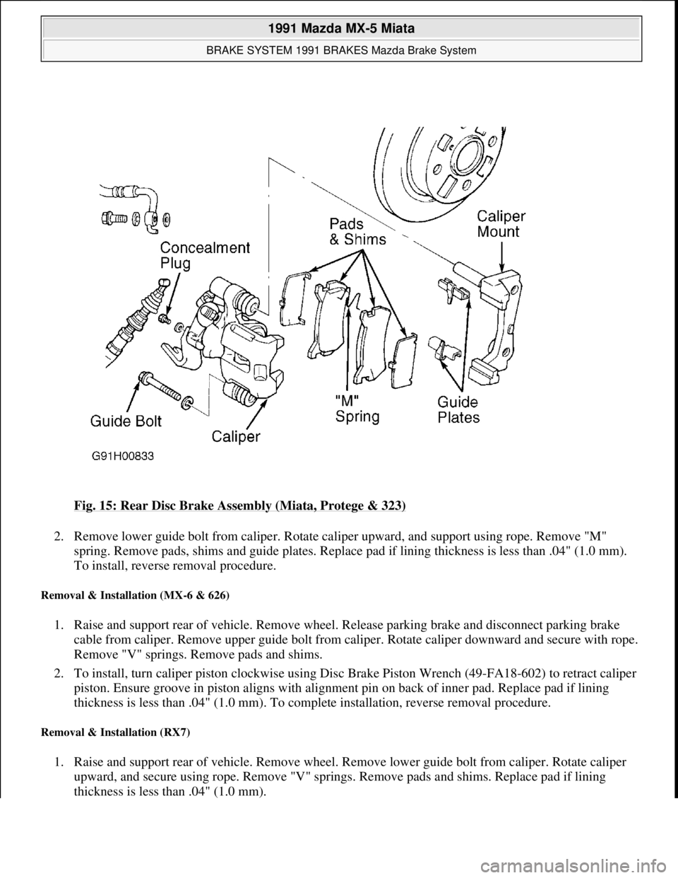
Fig. 15: Rear Disc Brake Assembly (Miata, Protege & 323)
2. Remove lower guide bolt from caliper. Rotate caliper upward, and support using rope. Remove "M"
spring. Remove pads, shims and guide plates. Replace pad if lining thickness is less than .04" (1.0 mm).
To install, reverse removal procedure.
Removal & Installation (MX-6 & 626)
1. Raise and support rear of vehicle. Remove wheel. Release parking brake and disconnect parking brake
cable from caliper. Remove upper guide bolt from caliper. Rotate caliper downward and secure with rope.
Remove "V" springs. Remove pads and shims.
2. To install, turn caliper piston clockwise using Disc Brake Piston Wrench (49-FA18-602) to retract caliper
piston. Ensure groove in piston aligns with alignment pin on back of inner pad. Replace pad if lining
thickness is less than .04" (1.0 mm). To complete installation, reverse removal procedure.
Removal & Installation (RX7)
1. Raise and support rear of vehicle. Remove wheel. Remove lower guide bolt from caliper. Rotate caliper
upward, and secure using rope. Remove "V" springs. Remove pads and shims. Replace pad if lining
thickness is less than .04" (1.0 mm).
1991 Mazda MX-5 Miata
BRAKE SYSTEM 1991 BRAKES Mazda Brake System
Microsoft
Sunday, July 05, 2009 2:18:08 PMPage 24 © 2005 Mitchell Repair Information Company, LLC.
Page 228 of 392
2. To install, turn caliper piston clockwise using Disc Brake Piston Wrench (49-FA18-602) to retract caliper
piston. Ensure groove in piston aligns with alignment pin on back of inner pad. To install remaining
components, reverse removal procedure.
Removal & Installation (929)
Raise and support rear of vehicle. Remove wheel. Remove lower guide bolt from caliper. Rotate caliper upward
and secure with rope. Remove pads and shims. Replace pad if lining thickness is less than .08" (2.0 mm). To
install, reverse removal procedure.
REAR BRAKE CALIPER
Removal & Installation
1. Raise and support rear of vehicle. On all models except 929, release parking brake and disconnect parking
brake cable from caliper. On all models, disconnect brake hose from caliper.
2. On Miata, Protege and 323, remove manual adjustment gear concealment plug from caliper. See Fig. 15
.
Insert an appropriate size Allen wrench through hole and turn manual adjustment gear counterclockwise
to retract caliper piston.
3. On all models, remove lower guide bolt from caliper. Rotate caliper upward. Pull caliper toward center of
vehicle to slide it off of caliper mount. To install, reverse removal procedure. Bleed hydraulic system.
REAR BRAKE ROTOR
Removal & Installation (Miata, Protege, RX7, 323 & 929)
Remove rear brake caliper. Remove rotor-to-hub screws. Remove rotor. Machine rotor if lateral runout exceeds
specification. Replace rotor if measured thickness is less than specified minimum thickness. See DISC BRAKE
SPECIFICATIONS at end of article. To install, reverse removal procedure.
Removal & Installation (MX-6 & 626)
1. Remove rear caliper, and wire aside. Remove grease cap. Remove lock nut. Remove rotor. Machine rotor
if lateral runout exceeds specification. Replace rotor if measured thickness is less than specified minimum
thickness. See DISC BRAKE SPECIFICATIONS
at end of article.
2. To install, reverse removal procedure. Tighten lock nut to 73-131 ft. lbs. (99-178 N.m). Check end play at
grease cap. If end play exceeds .008" (.20 mm), replace wheel bearings.
REAR BRAKE SHOES
Removal (B2200, B2600i & MPV)
With brake drum removed, remove brake shoe return springs, retaining springs and guide pins. See Fig. 16 or
Fig. 17
. Remove brake shoes. Remove parking brake strut, and disconnect parking brake cable from operating
lever of secondar
y shoe. Minimum lining thickness is .04" (1 mm).
1991 Mazda MX-5 Miata
BRAKE SYSTEM 1991 BRAKES Mazda Brake System
Microsoft
Sunday, July 05, 2009 2:18:08 PMPage 25 © 2005 Mitchell Repair Information Company, LLC.
Page 231 of 392

Fig. 18: View of Rear Drum Brake Assembly (Typical)
Courtesy of MAZDA MOTORS CORP.
Installation
1. Apply brake grease to brake shoe contact areas on backing plate. When installing adjuster between shoes,
insert a flat-tipped screwdriver between adjuster quadrant and meshing teeth on MX-6 and 626, or
between quadrant and knurled pin on Protege and 323. See Fig. 2
.
2. To fully retract adjuster, move quadrant until it touches backing plate. To complete installation, reverse
removal procedure. Adjust wheel bearings and stake lock nut.
Removal (Navajo)
1. Remove wheel assembly and drum. Place a wheel cylinder clamp over ends of wheel cylinder. Disengage
ad
justing lever from adjusting screw by pulling backwards on lever cable. See Fig. 19 .
1991 Mazda MX-5 Miata
BRAKE SYSTEM 1991 BRAKES Mazda Brake System
Microsoft
Sunday, July 05, 2009 2:18:08 PMPage 28 © 2005 Mitchell Repair Information Company, LLC.
Page 234 of 392
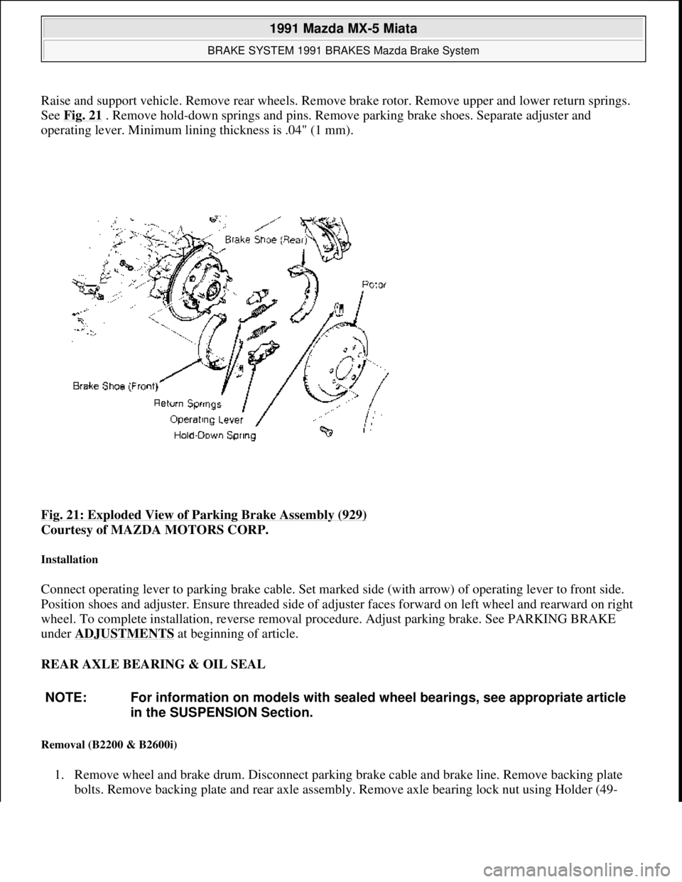
Raise and support vehicle. Remove rear wheels. Remove brake rotor. Remove upper and lower return springs.
See Fig. 21
. Remove hold-down springs and pins. Remove parking brake shoes. Separate adjuster and
operating lever. Minimum lining thickness is .04" (1 mm).
Fig. 21: Exploded View of Parking Brake Assembly (929)
Courtesy of MAZDA MOTORS CORP.
Installation
Connect operating lever to parking brake cable. Set marked side (with arrow) of operating lever to front side.
Position shoes and adjuster. Ensure threaded side of adjuster faces forward on left wheel and rearward on right
wheel. To complete installation, reverse removal procedure. Adjust parking brake. See PARKING BRAKE
under ADJUSTMENTS
at beginning of article.
REAR AXLE BEARING & OIL SEAL
Removal (B2200 & B2600i)
1. Remove wheel and brake drum. Disconnect parking brake cable and brake line. Remove backing plate
bolts. Remove backing plate and rear axle assembly. Remove axle bearing lock nut using Holder (49-
NOTE: For information on models with sealed wheel bearings, see appropriate article
in the SUSPENSION Section.
1991 Mazda MX-5 Miata
BRAKE SYSTEM 1991 BRAKES Mazda Brake System
Microsoft
Sunday, July 05, 2009 2:18:08 PMPage 31 © 2005 Mitchell Repair Information Company, LLC.
Page 235 of 392
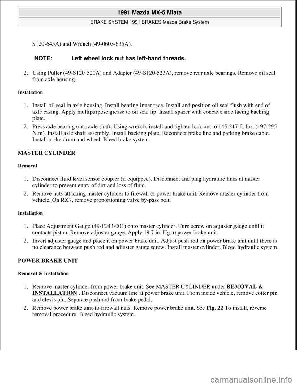
S120-645A) and Wrench (49-0603-635A).
2. Using Puller (49-S120-520A) and Adapter (49-S120-523A), remove rear axle bearings. Remove oil seal
from axle housing.
Installation
1. Install oil seal in axle housing. Install bearing inner race. Install and position oil seal flush with end of
axle casing. Apply multipurpose grease to oil seal lip. Install spacer with concave side facing backing
plate.
2. Press axle bearing onto axle shaft. Using wrench, install and tighten lock nut to 145-217 ft. lbs. (197-295
N.m). Install axle shaft assembly. Install backing plate. Reconnect brake line and parking brake cable.
Install brake drum and wheel. Bleed brake system.
MASTER CYLINDER
Removal
1. Disconnect fluid level sensor coupler (if equipped). Disconnect and plug hydraulic lines at master
cylinder to prevent entry of dirt and loss of fluid.
2. Remove nuts attaching master cylinder to firewall or power brake unit. Remove master cylinder from
vehicle. On RX7, remove proportioning valve by-pass bolt.
Installation
1. Place Adjustment Gauge (49-F043-001) onto master cylinder. Turn screw on adjuster gauge until it
contacts piston. Remove adjuster gauge. Apply 19.7 in. Hg to power brake unit.
2. Invert adjuster gauge and place it on power brake unit. Adjust push rod on power brake unit until there is
no clearance between push rod and adjuster gauge screw. Install master cylinder. Bleed hydraulic system.
POWER BRAKE UNIT
Removal & Installation
1. Remove master cylinder from power brake unit. See MASTER CYLINDER under REMOVAL &
INSTALLATION . Disconnect vacuum line at power brake unit. From inside vehicle, remove cotter pin
and clevis pin. Separate push rod from brake pedal.
2. Remove power brake unit-to-firewall nuts. Remove power brake unit. See Fig. 22
To install, reverse
removal procedure. Bleed hydraulic system. NOTE: Left wheel lock nut has left-hand threads.
1991 Mazda MX-5 Miata
BRAKE SYSTEM 1991 BRAKES Mazda Brake System
Microsoft
Sunday, July 05, 2009 2:18:08 PMPage 32 © 2005 Mitchell Repair Information Company, LLC.
Page 242 of 392
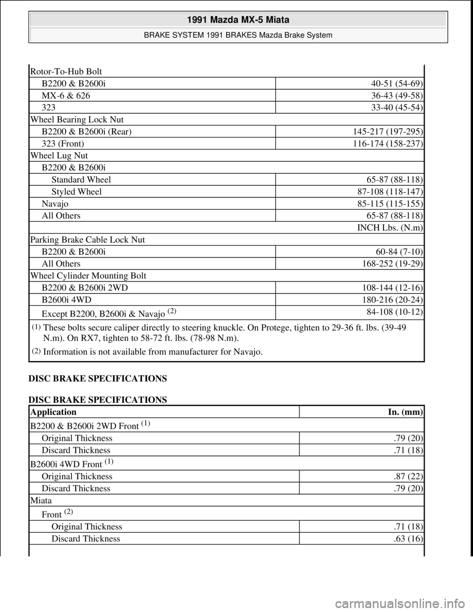
DISC BRAKE SPECIFICATIONS
DISC BRAKE SPECIFICATIONS
Rotor-To-Hub Bolt
B2200 & B2600i40-51 (54-69)
MX-6 & 62636-43 (49-58)
32333-40 (45-54)
Wheel Bearing Lock Nut
B2200 & B2600i (Rear)145-217 (197-295)
323 (Front)116-174 (158-237)
Wheel Lug Nut
B2200 & B2600i
Standard Wheel65-87 (88-118)
Styled Wheel87-108 (118-147)
Navajo85-115 (115-155)
All Others65-87 (88-118)
INCH Lbs. (N.m)
Parking Brake Cable Lock Nut
B2200 & B2600i60-84 (7-10)
All Others168-252 (19-29)
Wheel Cylinder Mounting Bolt
B2200 & B2600i 2WD108-144 (12-16)
B2600i 4WD180-216 (20-24)
Except B2200, B2600i & Navajo (2) 84-108 (10-12)
(1)These bolts secure caliper directly to steering knuckle. On Protege, tighten to 29-36 ft. lbs. (39-49
N.m). On RX7, tighten to 58-72 ft. lbs. (78-98 N.m).
(2)Information is not available from manufacturer for Navajo.
ApplicationIn. (mm)
B2200 & B2600i 2WD Front (1)
Original Thickness.79 (20)
Discard Thickness.71 (18)
B2600i 4WD Front (1)
Original Thickness.87 (22)
Discard Thickness.79 (20)
Miata
Front (2)
Original Thickness.71 (18)
Discard Thickness.63 (16)
1991 Mazda MX-5 Miata
BRAKE SYSTEM 1991 BRAKES Mazda Brake System
Microsoft
Sunday, July 05, 2009 2:18:09 PMPage 39 © 2005 Mitchell Repair Information Company, LLC.
Page 261 of 392
3. Using Bearing Nut Wrench (49 0603 635A ) and Shaft Holder (49 S120 645A ), remove bearing lock nut
from axle shaft. Remove bearing and bearing retainer from axle using Puller (49 S120 520A ). Remove
outer race from hub.
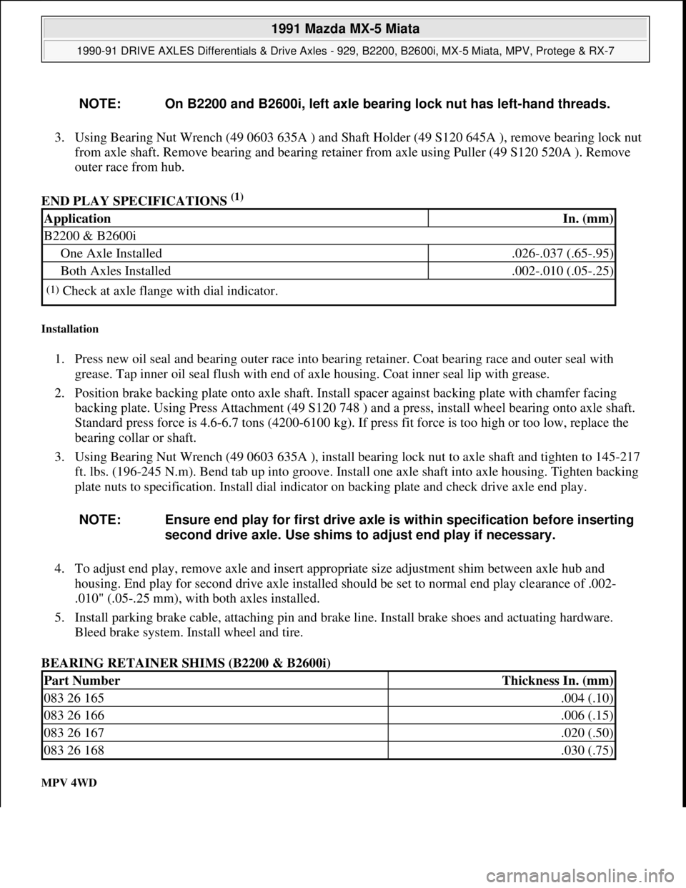
END PLAY SPECIFICATIONS
(1)
Installation
1. Press new oil seal and bearing outer race into bearing retainer. Coat bearing race and outer seal with
grease. Tap inner oil seal flush with end of axle housing. Coat inner seal lip with grease.
2. Position brake backing plate onto axle shaft. Install spacer against backing plate with chamfer facing
backing plate. Using Press Attachment (49 S120 748 ) and a press, install wheel bearing onto axle shaft.
Standard press force is 4.6-6.7 tons (4200-6100 kg). If press fit force is too high or too low, replace the
bearing collar or shaft.
3. Using Bearing Nut Wrench (49 0603 635A ), install bearing lock nut to axle shaft and tighten to 145-217
ft. lbs. (196-245 N.m). Bend tab up into groove. Install one axle shaft into axle housing. Tighten backing
plate nuts to specification. Install dial indicator on backing plate and check drive axle end play.
4. To adjust end play, remove axle and insert appropriate size adjustment shim between axle hub and
housing. End play for second drive axle installed should be set to normal end play clearance of .002-
.010" (.05-.25 mm), with both axles installed.
5. Install parking brake cable, attaching pin and brake line. Install brake shoes and actuating hardware.
Bleed brake system. Install wheel and tire.
BEARING RETAINER SHIMS (B2200 & B2600i)
MPV 4WD
NOTE: On B2200 and B2600i, left axle bearing lock nut has left-hand threads.
ApplicationIn. (mm)
B2200 & B2600i
One Axle Installed.026-.037 (.65-.95)
Both Axles Installed.002-.010 (.05-.25)
(1)Check at axle flange with dial indicator.
NOTE: Ensure end play for first drive axle is within specification before inserting
second drive axle. Use shims to adjust end play if necessary.
Part NumberThickness In. (mm)
083 26 165.004 (.10)
083 26 166.006 (.15)
083 26 167.020 (.50)
083 26 168.030 (.75)
1991 Mazda MX-5 Miata
1990-91 DRIVE AXLES Differentials & Drive Axles - 929, B2200, B2600i, MX-5 Miata, MPV, Protege & RX-7
Microsoft
Sunday, July 05, 2009 2:17:01 PMPage 3 © 2005 Mitchell Repair Information Company, LLC.
Page 267 of 392
2. Support transmission with a jack. Remove PPF bracket from rear transmission extension housing.
Remove PPF-to-differential side bolts and pry out spacer. Remove PPF/differential mounting spacer. See
Fig. 6
. Install metric bolt (M14 X 1.5) into sleeve. See Fig. 7 .
3. Twist bolt side-to-side while pulling bolt downward. Install a metric bolt (M6 X 1) into hole in housing
block to hold sleeve and remove long bolt (M14 X 1.5). Remove short bolt (M6 X 1).
4. Remove PPF-to-transmission side bolts and remove PPF. Mark and disconnect CV joint drive axles from
differential assembly and wire aside. Remove differential carrier-to-housing nuts. Remove differential
carrier.
INSTALLATION
1. To install, reverse removal procedure. Apply Sealant (8527 77 739 ) to carrier mating flange. Align marks
made during removal and install differential carrier. Install differential. Raise transmission until engine
and transmission are level.
2. To install Power Plant Frame (PPF), position PPF in place. Install PPF/differential mounting spacer and
tighten bolts to 27-38 ft. lbs. (37-52 N.m). Install PPF-to-transmission side mounting bolts and tighten.
3. Ensure sleeve is installed into PPF housing block. Install spacer and bolts. Ensure reamer bolt is installed
into front hole and tighten. See Fig. 6
.
4. Install transmission-to-PPF bracket. Install remaining PPF bolts and tighten all bolts to specification. See
TORQUE SPECIFICATIONS
. To complete installation, reverse removal procedure.
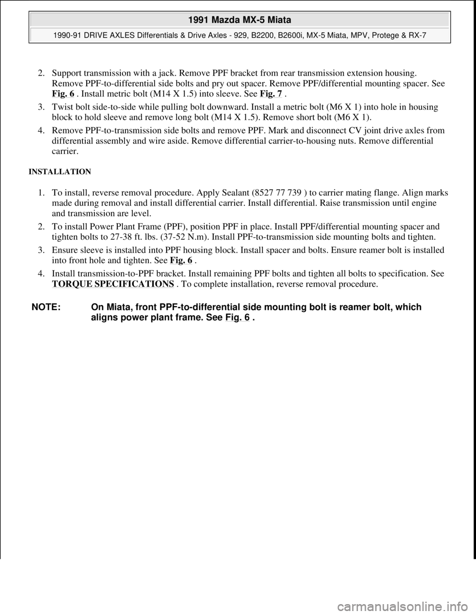
NOTE: On Miata, front PPF-to-differential side mounting bolt is reamer bolt, which
aligns power plant frame. See Fig. 6
.
1991 Mazda MX-5 Miata
1990-91 DRIVE AXLES Differentials & Drive Axles - 929, B2200, B2600i, MX-5 Miata, MPV, Protege & RX-7
Microsoft
Sunday, July 05, 2009 2:17:01 PMPage 9 © 2005 Mitchell Repair Information Company, LLC.