belt MAZDA MIATA 1991 Factory User Guide
[x] Cancel search | Manufacturer: MAZDA, Model Year: 1991, Model line: MIATA, Model: MAZDA MIATA 1991Pages: 392, PDF Size: 29.45 MB
Page 290 of 392
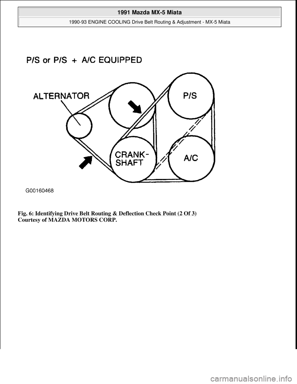
Fig. 6: Identifying Drive Belt Routing & Deflection Check Point (2 Of 3)
Courtesy of MAZDA MOTORS CORP.
1991 Mazda MX-5 Miata
1990-93 ENGINE COOLING Drive Belt Routing & Adjustment - MX-5 Miata
Microsoft
Sunday, July 05, 2009 2:14:16 PMPage 6 © 2005 Mitchell Repair Information Company, LLC.
Page 291 of 392
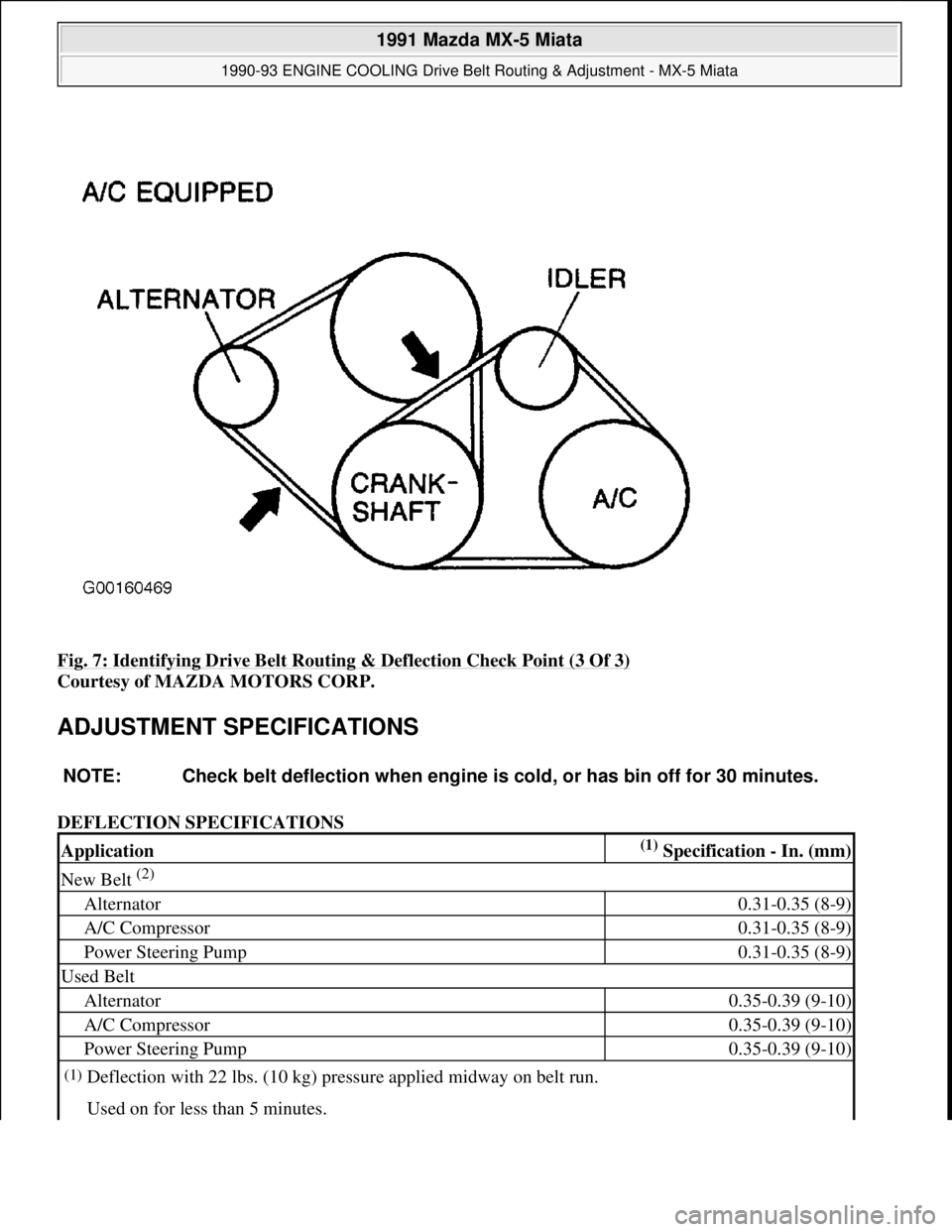
Fig. 7: Identifying Drive Belt Routing & Deflection Check Point (3 Of 3)
Courtesy of MAZDA MOTORS CORP.
ADJUSTMENT SPECIFICATIONS
DEFLECTION SPECIFICATIONS
NOTE: Check belt deflection when engine is cold, or has bin off for 30 minutes.
Application(1) Specification - In. (mm)
New Belt (2)
Alternator0.31-0.35 (8-9)
A/C Compressor0.31-0.35 (8-9)
Power Steering Pump0.31-0.35 (8-9)
Used Belt
Alternator0.35-0.39 (9-10)
A/C Compressor0.35-0.39 (9-10)
Power Steering Pump0.35-0.39 (9-10)
(1)Deflection with 22 lbs. (10 kg) pressure applied midway on belt run.
Used on for less than 5 minutes.
1991 Mazda MX-5 Miata
1990-93 ENGINE COOLING Drive Belt Routing & Adjustment - MX-5 Miata
Microsoft
Sunday, July 05, 2009 2:14:16 PMPage 7 © 2005 Mitchell Repair Information Company, LLC.
Page 292 of 392
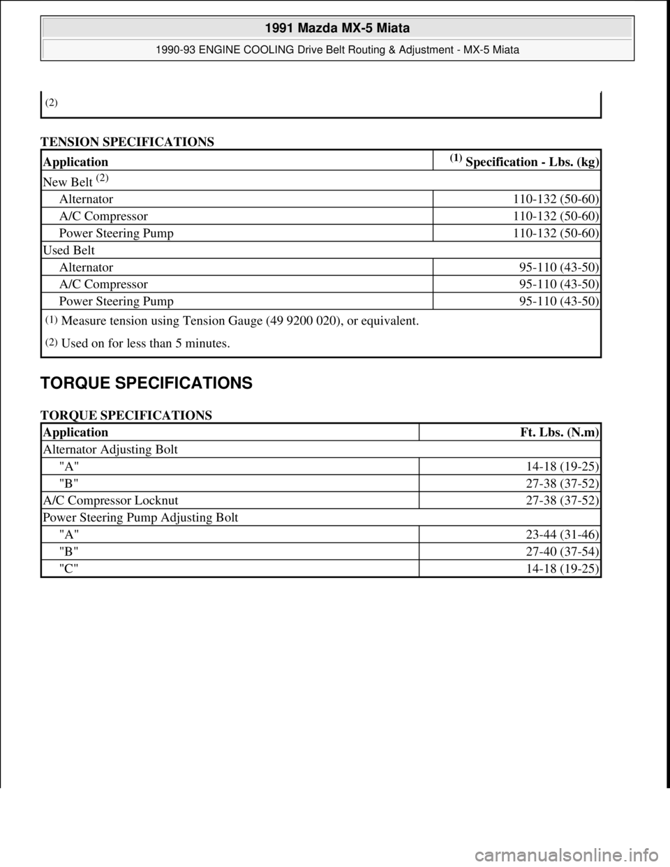
TENSION SPECIFICATIONS
TORQUE SPECIFICATIONS
TORQUE SPECIFICATIONS
(2)
Application(1) Specification - Lbs. (kg)
New Belt (2)
Alternator110-132 (50-60)
A/C Compressor110-132 (50-60)
Power Steering Pump110-132 (50-60)
Used Belt
Alternator95-110 (43-50)
A/C Compressor95-110 (43-50)
Power Steering Pump95-110 (43-50)
(1)Measure tension using Tension Gauge (49 9200 020), or equivalent.
(2)Used on for less than 5 minutes.
ApplicationFt. Lbs. (N.m)
Alternator Adjusting Bolt
"A"14-18 (19-25)
"B"27-38 (37-52)
A/C Compressor Locknut27-38 (37-52)
Power Steering Pump Adjusting Bolt
"A"23-44 (31-46)
"B"27-40 (37-54)
"C"14-18 (19-25)
1991 Mazda MX-5 Miata
1990-93 ENGINE COOLING Drive Belt Routing & Adjustment - MX-5 Miata
Microsoft
Sunday, July 05, 2009 2:14:16 PMPage 8 © 2005 Mitchell Repair Information Company, LLC.
Page 295 of 392
SWITCHES
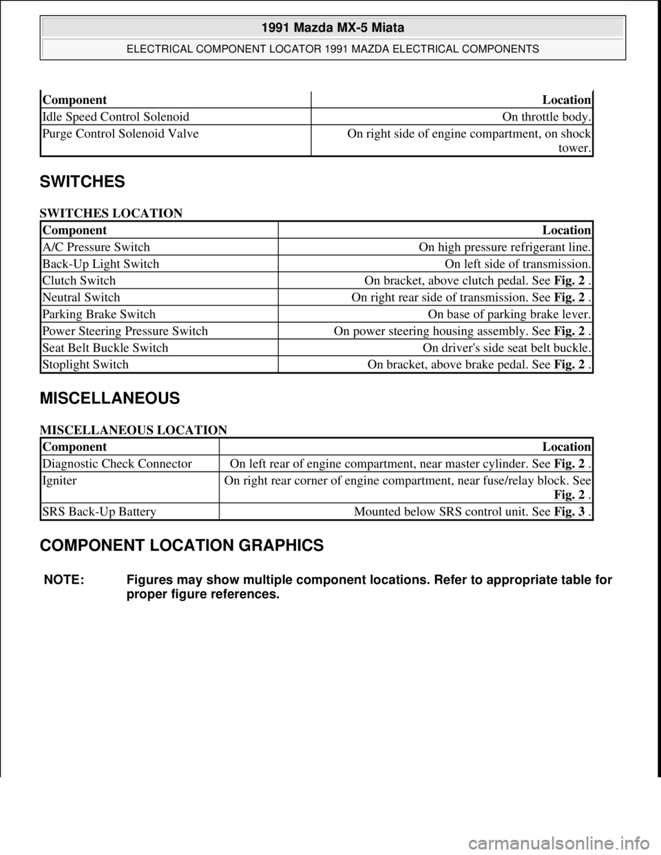
SWITCHES LOCATION
MISCELLANEOUS
MISCELLANEOUS LOCATION
COMPONENT LOCATION GRAPHICS
ComponentLocation
Idle Speed Control SolenoidOn throttle body.
Purge Control Solenoid ValveOn right side of engine compartment, on shock
tower.
ComponentLocation
A/C Pressure SwitchOn high pressure refrigerant line.
Back-Up Light SwitchOn left side of transmission.
Clutch SwitchOn bracket, above clutch pedal. See Fig. 2 .
Neutral SwitchOn right rear side of transmission. See Fig. 2 .
Parking Brake SwitchOn base of parking brake lever.
Power Steering Pressure SwitchOn power steering housing assembly. See Fig. 2 .
Seat Belt Buckle SwitchOn driver's side seat belt buckle.
Stoplight SwitchOn bracket, above brake pedal. See Fig. 2 .
ComponentLocation
Diagnostic Check ConnectorOn left rear of engine compartment, near master cylinder. See Fig. 2 .
IgniterOn right rear corner of engine compartment, near fuse/relay block. See
Fig. 2
.
SRS Back-Up BatteryMounted below SRS control unit. See Fig. 3 .
NOTE: Figures may show multiple component locations. Refer to appropriate table for
proper figure references.
1991 Mazda MX-5 Miata
ELECTRICAL COMPONENT LOCATOR 1991 MAZDA ELECTRICAL COMPONENTS
Microsoft
Sunday, July 05, 2009 2:15:23 PMPage 3 © 2005 Mitchell Repair Information Company, LLC.
Page 327 of 392
A/C-HEATER SYSTEM - MANUAL
1990-92 Manual A/C-Heater Systems
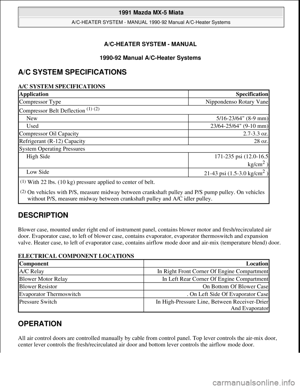
A/C SYSTEM SPECIFICATIONS
A/C SYSTEM SPECIFICATIONS
DESCRIPTION
Blower case, mounted under right end of instrument panel, contains blower motor and fresh/recirculated air
door. Evaporator case, to left of blower case, contains evaporator, evaporator thermoswitch and expansion
valve. Heater case, to left of evaporator case, contains airflow mode door and air-mix (temperature blend) door.
ELECTRICAL COMPONENT LOCATIONS
OPERATION
All air control doors are controlled manually by cable from control panel. Top lever controls the air-mix door,
center lever controls the fresh/recirculated air door and bottom lever controls the airflow mode door.
ApplicationSpecification
Compressor TypeNippondenso Rotary Vane
Compressor Belt Deflection (1) (2)
New5/16-23/64" (8-9 mm)
Used23/64-25/64" (9-10 mm)
Compressor Oil Capacity2.7-3.3 oz.
Refrigerant (R-12) Capacity28 oz.
System Operating Pressures
High Side171-235 psi (12.0-16.5
kg/cm
2 )
Low Side21-43 psi (1.5-3.0 kg/cm2 )
(1)With 22 lbs. (10 kg) pressure applied to center of belt.
(2)On vehicles with P/S, measure midway between crankshaft pulley and P/S pump pulley. On vehicles
without P/S, measure midway between crankshaft pulley and A/C idler pulley.
ComponentLocation
A/C RelayIn Right Front Corner Of Engine Compartment
Blower Motor RelayIn Left Rear Corner Of Engine Compartment
Blower ResistorOn Bottom Of Blower Case
Evaporator Thermoswitch. On Left Side Of Evaporator Case
Pressure SwitchIn High-Pressure Line, Between Receiver-Drier
And Evaporator
1991 Mazda MX-5 Miata
A/C-HEATER SYSTEM - MANUAL 1990-92 Manual A/C-Heater Systems
1991 Mazda MX-5 Miata
A/C-HEATER SYSTEM - MANUAL 1990-92 Manual A/C-Heater Systems
Microsoft
Sunday, July 05, 2009 2:11:52 PMPage 1 © 2005 Mitchell Repair Information Company, LLC.
Microsoft
Sunday, July 05, 2009 2:11:56 PMPage 1 © 2005 Mitchell Repair Information Company, LLC.
Page 333 of 392

Disconnect electrical connectors from blower case. Remove glove box. Loosen seal plate between blower motor
case and evaporator case. Remove blower motor case nuts. Remove case and seal plate. To install, reverse
removal procedure.
COMPRESSOR
Removal & Installation
1. Disconnect negative battery cable. Discharge A/C system using approved refrigerant recovery/recycling
equipment. Disconnect compressor clutch connector. Disconnect refrigerant lines from compressor.
Remove drive belt.
2. Raise and support vehicle. Remove compressor mounting bolts and remove compressor. To install,
reverse removal procedure. Adjust drive belt to specified tension. Evacuate and charge system.
CONDENSER & RECEIVER-DRIER
Removal & Installation
Discharge A/C system using approved refrigerant recovery/recycling equipment. Raise and support vehicle.
Remove splash shield and air guide. Remove condenser and receiver-drier as an assembly. To install, reverse
removal procedure. Evacuate and charge system.
CONTROL PANEL
Removal & Installation
Remove rear console assembly. See Fig. 4 . Remove vent outlets from center panel assembly. Remove center
panel assembly. Remove control panel screws. Pull control panel from hole. Disconnect door control cables
from back of control panel and remove panel. To install, reverse removal procedure.
EVAPORATOR CORE & THERMOSWITCH
Removal & Installation
1. Discharge A/C system using approved refrigerant recovery/recycling equipment. Remove condenser and
receiver-drier as an assembly. Disconnect low-pressure and high-pressure pipes from evaporator tubes at
engine compartment firewall.
2. Remove right undercover and glove box. Disconnect thermoswitch electrical connector. Loosen left seal
plate (between heater case and evaporator case). Loosen right seal plate (between evaporator case and
blower motor case).
3. Remove evaporator case. Disassemble evaporator case, and remove evaporator core and thermoswitch.
See Fig. 3
. To install, reverse removal procedure. Evacuate and charge system.
1991 Mazda MX-5 Miata
A/C-HEATER SYSTEM - MANUAL 1990-92 Manual A/C-Heater Systems
Microsoft
Sunday, July 05, 2009 2:11:52 PMPage 7 © 2005 Mitchell Repair Information Company, LLC.
Page 340 of 392
LUBRICATION
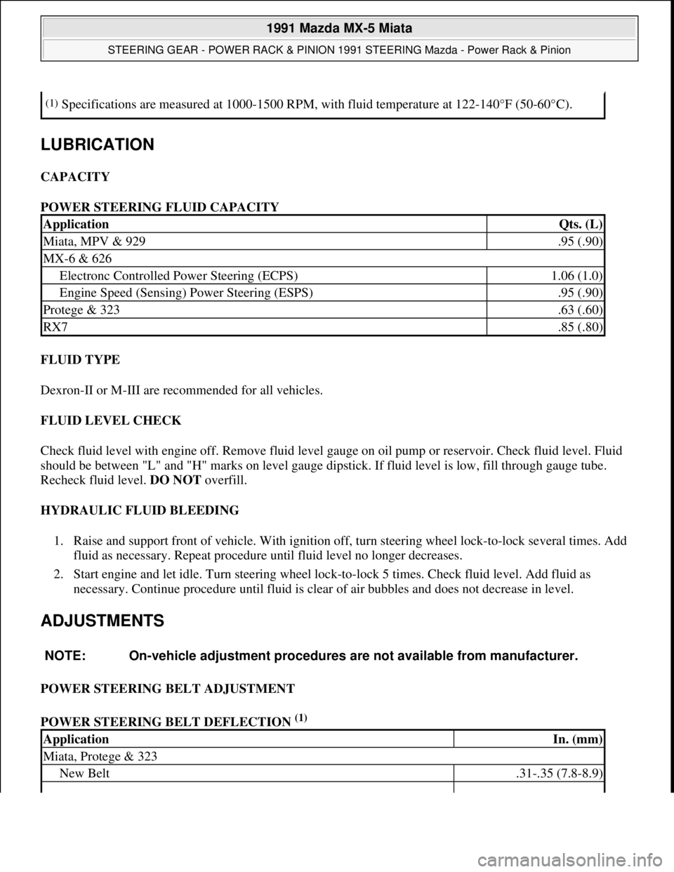
CAPACITY
POWER STEERING FLUID CAPACITY
FLUID TYPE
Dexron-II or M-III are recommended for all vehicles.
FLUID LEVEL CHECK
Check fluid level with engine off. Remove fluid level gauge on oil pump or reservoir. Check fluid level. Fluid
should be between "L" and "H" marks on level gauge dipstick. If fluid level is low, fill through gauge tube.
Recheck fluid level. DO NOT overfill.
HYDRAULIC FLUID BLEEDING
1. Raise and support front of vehicle. With ignition off, turn steering wheel lock-to-lock several times. Add
fluid as necessary. Repeat procedure until fluid level no longer decreases.
2. Start engine and let idle. Turn steering wheel lock-to-lock 5 times. Check fluid level. Add fluid as
necessary. Continue procedure until fluid is clear of air bubbles and does not decrease in level.
ADJUSTMENTS
POWER STEERING BELT ADJUSTMENT
POWER STEERING BELT DEFLECTION
(1)
(1)Specifications are measured at 1000-1500 RPM, with fluid temperature at 122-140°F (50-60°C).
ApplicationQts. (L)
Miata, MPV & 929.95 (.90)
MX-6 & 626
Electronc Controlled Power Steering (ECPS)1.06 (1.0)
Engine Speed (Sensing) Power Steering (ESPS).95 (.90)
Protege & 323.63 (.60)
RX7.85 (.80)
NOTE: On-vehicle adjustment procedures are not available from manufacturer.
ApplicationIn. (mm)
Miata, Protege & 323
New Belt.31-.35 (7.8-8.9)
1991 Mazda MX-5 Miata
STEERING GEAR - POWER RACK & PINION 1991 STEERING Mazda - Power Rack & Pinion
Microsoft
Sunday, July 05, 2009 2:10:15 PMPage 3 © 2005 Mitchell Repair Information Company, LLC.
Page 341 of 392

REMOVAL & INSTALLATION
STEERING GEAR
Removal & Installation (Miata & MPV)
1. Disconnect negative battery cable. Raise and support front of vehicle. Remove front wheels. Remove
cotter pins and castle nuts from tie rod ends.
2. Using puller, remove tie rods from steering knuckles. Remove steering column intermediate shaft-to-
steering gear pinion shaft bolt. Mark reference lines on pressure pipe fittings.
3. Remove pressure and return hose connections from steering gear. Remove 2 steering bracket-to-frame
mounting through bolts. Remove steering gear and linkage with steering bracket attached from under the
vehicle.
4. To install, reverse removal procedure. Fill and bleed system. Tighten bolts to specification. See
TORQUE SPECIFICATIONS
table. Tighten steering gear-to-mounting bracket bolts (4) in the
following order: left front, right front, left rear, right rear.
Removal & Installation (MX-6 & 626)
1. Disconnect negative battery cable and power steering pressure switch connectors. Raise and support front
of vehicle. Remove front wheels.
2. Remove cotter pins and castle nuts from tie rod ends. Using puller, remove tie rods from steering
knuckles. Remove steerin
g column intermediate shaft-to-steering gear pinion shaft bolt.
Used Belt.35-.39 (8.9-10.0)
MPV
V6
New Belt.28-.30 (7.1-7.6)
Used Belt.30-.32 (7.6-8.1)
4-Cylinder
New Belt.26-.28 (6.6-7.1)
Used Belt.28-.31 (7.1-7.8)
MX-6 & 626
New Belt.31-.36 (7.8-9.1)
Used Belt.35-.43 (8.9-10.9)
RX7
New Belt.43-.51 (10.9-12.9)
Used Belt.55-.63 (14.0-16.0)
929
New Belt.28-.35 (7.1-8.9)
Used Belt.35-.43 (8.9-10.9)
(1)Belt deflection is measured at midpoint between idler pulley and pump, with 22 lbs. (10 kg.) of
pressure applied.
1991 Mazda MX-5 Miata
STEERING GEAR - POWER RACK & PINION 1991 STEERING Mazda - Power Rack & Pinion
Microsoft
Sunday, July 05, 2009 2:10:15 PMPage 4 © 2005 Mitchell Repair Information Company, LLC.
Page 343 of 392

table. Bleed air from system. Check fluid level. Check for leaks. Adjust alignment (if necessary).
POWER STEERING PUMP
Removal & Installation
1. Raise and support front of vehicle. On MX-6 and 626, remove right wheel and splash shield. On all
models remove belt, alternator and hydraulic lines from pump.
2. On Protege and 323, disconnect air cleaner duct and pressure switch. On all models, cap lines to prevent
contamination. Remove bracket-to-pump bolts.
3. To install, reverse removal procedure. Adjust belt tension. See POWER STEERING BELT
DEFLECTION TABLE under ADJUSTMENTS. Bleed air from system. Check for leaks.
OVERHAUL
STEERING GEAR
NOTE: See Fig. 2
-8 for exploded views of rack and pinion steering gears.
1991 Mazda MX-5 Miata
STEERING GEAR - POWER RACK & PINION 1991 STEERING Mazda - Power Rack & Pinion
Microsoft
Sunday, July 05, 2009 2:10:15 PMPage 6 © 2005 Mitchell Repair Information Company, LLC.
Page 382 of 392
MAZDA
1.6L & 1.8L 4-Cylinder - 1986-95
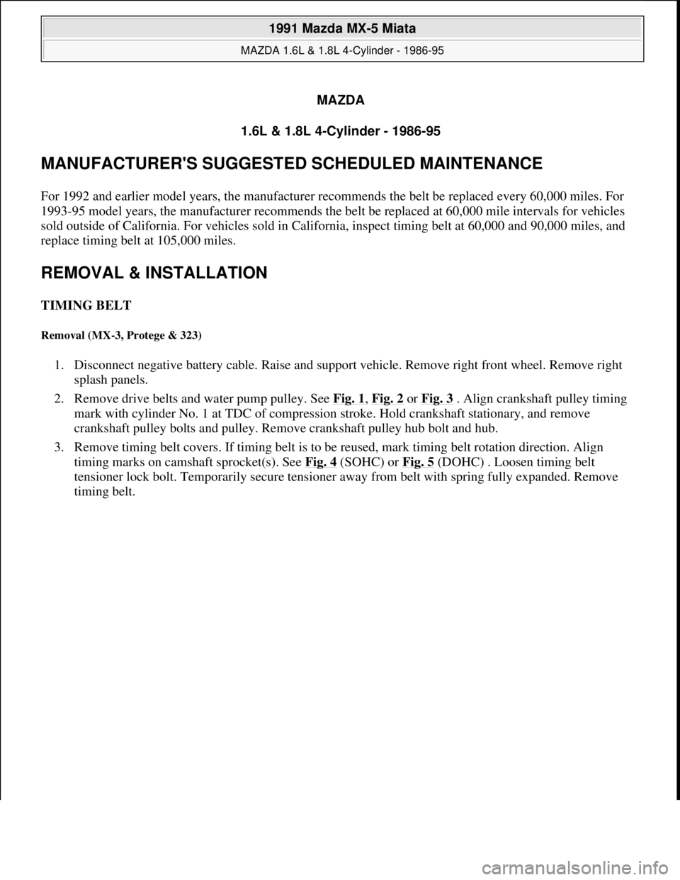
MANUFACTURER'S SUGGESTED SCHEDULED MAINTENANCE
For 1992 and earlier model years, the manufacturer recommends the belt be replaced every 60,000 miles. For
1993-95 model years, the manufacturer recommends the belt be replaced at 60,000 mile intervals for vehicles
sold outside of California. For vehicles sold in California, inspect timing belt at 60,000 and 90,000 miles, and
replace timing belt at 105,000 miles.
REMOVAL & INSTALLATION
TIMING BELT
Removal (MX-3, Protege & 323)
1. Disconnect negative battery cable. Raise and support vehicle. Remove right front wheel. Remove right
splash panels.
2. Remove drive belts and water pump pulley. See Fig. 1
, Fig. 2 or Fig. 3 . Align crankshaft pulley timing
mark with cylinder No. 1 at TDC of compression stroke. Hold crankshaft stationary, and remove
crankshaft pulley bolts and pulley. Remove crankshaft pulley hub bolt and hub.
3. Remove timing belt covers. If timing belt is to be reused, mark timing belt rotation direction. Align
timing marks on camshaft sprocket(s). See Fig. 4
(SOHC) or Fig. 5 (DOHC) . Loosen timing belt
tensioner lock bolt. Temporarily secure tensioner away from belt with spring fully expanded. Remove
timin
g belt.
1991 Mazda MX-5 Miata
MAZDA 1.6L & 1.8L 4-Cylinder - 1986-95
1991 Mazda MX-5 Miata
MAZDA 1.6L & 1.8L 4-Cylinder - 1986-95
Microsoft
Sunday, July 05, 2009 2:12:43 PMPage 1 © 2005 Mitchell Repair Information Company, LLC.
Microsoft
Sunday, July 05, 2009 2:12:56 PMPage 1 © 2005 Mitchell Repair Information Company, LLC.