brake sensor MAZDA MIATA 1991 Factory User Guide
[x] Cancel search | Manufacturer: MAZDA, Model Year: 1991, Model line: MIATA, Model: MAZDA MIATA 1991Pages: 392, PDF Size: 29.45 MB
Page 235 of 392

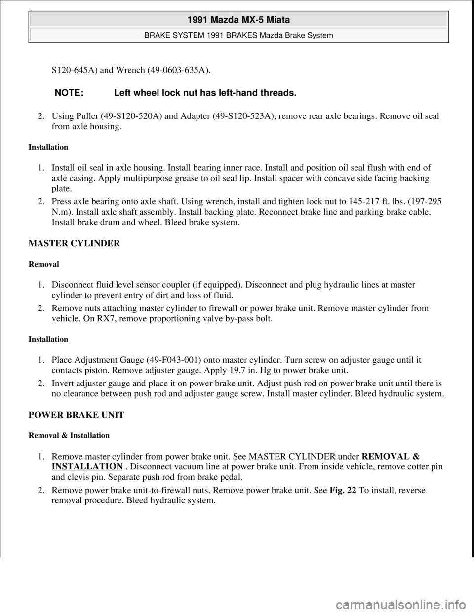
S120-645A) and Wrench (49-0603-635A).
2. Using Puller (49-S120-520A) and Adapter (49-S120-523A), remove rear axle bearings. Remove oil seal
from axle housing.
Installation
1. Install oil seal in axle housing. Install bearing inner race. Install and position oil seal flush with end of
axle casing. Apply multipurpose grease to oil seal lip. Install spacer with concave side facing backing
plate.
2. Press axle bearing onto axle shaft. Using wrench, install and tighten lock nut to 145-217 ft. lbs. (197-295
N.m). Install axle shaft assembly. Install backing plate. Reconnect brake line and parking brake cable.
Install brake drum and wheel. Bleed brake system.
MASTER CYLINDER
Removal
1. Disconnect fluid level sensor coupler (if equipped). Disconnect and plug hydraulic lines at master
cylinder to prevent entry of dirt and loss of fluid.
2. Remove nuts attaching master cylinder to firewall or power brake unit. Remove master cylinder from
vehicle. On RX7, remove proportioning valve by-pass bolt.
Installation
1. Place Adjustment Gauge (49-F043-001) onto master cylinder. Turn screw on adjuster gauge until it
contacts piston. Remove adjuster gauge. Apply 19.7 in. Hg to power brake unit.
2. Invert adjuster gauge and place it on power brake unit. Adjust push rod on power brake unit until there is
no clearance between push rod and adjuster gauge screw. Install master cylinder. Bleed hydraulic system.
POWER BRAKE UNIT
Removal & Installation
1. Remove master cylinder from power brake unit. See MASTER CYLINDER under REMOVAL &
INSTALLATION . Disconnect vacuum line at power brake unit. From inside vehicle, remove cotter pin
and clevis pin. Separate push rod from brake pedal.
2. Remove power brake unit-to-firewall nuts. Remove power brake unit. See Fig. 22
To install, reverse
removal procedure. Bleed hydraulic system. NOTE: Left wheel lock nut has left-hand threads.
1991 Mazda MX-5 Miata
BRAKE SYSTEM 1991 BRAKES Mazda Brake System
Microsoft
Sunday, July 05, 2009 2:18:08 PMPage 32 © 2005 Mitchell Repair Information Company, LLC.
Page 266 of 392

B2600i and MPV, remove brake drum and drive axles. See REAR AXLE SHAFTS & BEARINGS. On
Protege 4WD, RX7 and 929, disconnect CV joint drive axles from differential assembly and wire aside.
2. On all models, mark flanges and disconnect drive shaft. Remove ABS sensor (if equipped). On RX7,
remove rear exhaust system and differential mount on left side of pinion flange. Remove hanger mounts
and allow left side to hang down. Disconnect sublinks and remove differential.
3. On Protege 4WD and 929 models, remove differential housing assembly-to-chassis mounting bolts.
Remove differential housing assembly from vehicle. On all models, remove differential carrier-to-
housing nuts. Remove differential carrier.
Installation
To install, reverse removal procedure. Apply Sealant (8527 77 739 ) to carrier mating flange. Align marks made
during removal. Refill differential with correct type and amount of lubricant. Tighten all fasteners to
specification. See TORQUE SPECIFICATIONS
.
Fig. 4: Exploded View of Differential Assembly (RX7)
Courtesy of MAZDA MOTORS CORP.
Removal (Miata)
1. Raise and support vehicle. Drain differential. Mark flanges and remove drive shaft. Note locations and
disconnect wiring harness from Power Plant Frame (PPF). See Fig. 5
.
1991 Mazda MX-5 Miata
1990-91 DRIVE AXLES Differentials & Drive Axles - 929, B2200, B2600i, MX-5 Miata, MPV, Protege & RX-7
Microsoft
Sunday, July 05, 2009 2:17:01 PMPage 8 © 2005 Mitchell Repair Information Company, LLC.
Page 294 of 392

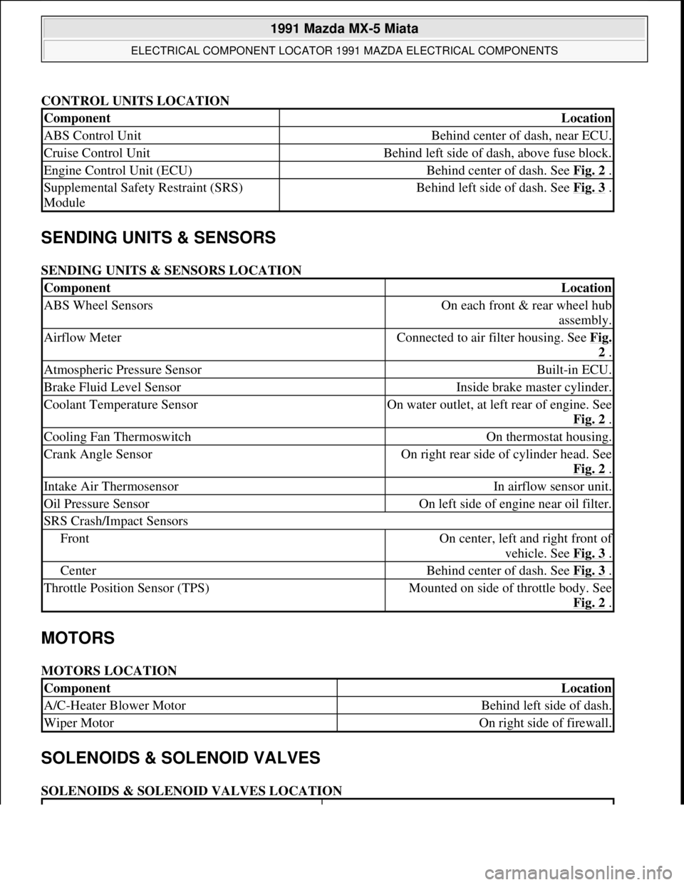
CONTROL UNITS LOCATION
SENDING UNITS & SENSORS
SENDING UNITS & SENSORS LOCATION
MOTORS
MOTORS LOCATION
SOLENOIDS & SOLENOID VALVES
SOLENOIDS & SOLENOID VALVES LOCATION
ComponentLocation
ABS Control UnitBehind center of dash, near ECU.
Cruise Control UnitBehind left side of dash, above fuse block.
Engine Control Unit (ECU)Behind center of dash. See Fig. 2 .
Supplemental Safety Restraint (SRS)
ModuleBehind left side of dash. See Fig. 3 .
ComponentLocation
ABS Wheel SensorsOn each front & rear wheel hub
assembly.
Airflow MeterConnected to air filter housing. See Fig.
2 .
Atmospheric Pressure SensorBuilt-in ECU.
Brake Fluid Level SensorInside brake master cylinder.
Coolant Temperature SensorOn water outlet, at left rear of engine. See
Fig. 2
.
Cooling Fan ThermoswitchOn thermostat housing.
Crank Angle SensorOn right rear side of cylinder head. See
Fig. 2
.
Intake Air ThermosensorIn airflow sensor unit.
Oil Pressure SensorOn left side of engine near oil filter.
SRS Crash/Impact Sensors
FrontOn center, left and right front of
vehicle. See Fig. 3
.
CenterBehind center of dash. See Fig. 3 .
Throttle Position Sensor (TPS)Mounted on side of throttle body. See
Fig. 2
.
ComponentLocation
A/C-Heater Blower MotorBehind left side of dash.
Wiper MotorOn right side of firewall.
1991 Mazda MX-5 Miata
ELECTRICAL COMPONENT LOCATOR 1991 MAZDA ELECTRICAL COMPONENTS
Microsoft
Sunday, July 05, 2009 2:15:23 PMPage 2 © 2005 Mitchell Repair Information Company, LLC.
Page 305 of 392

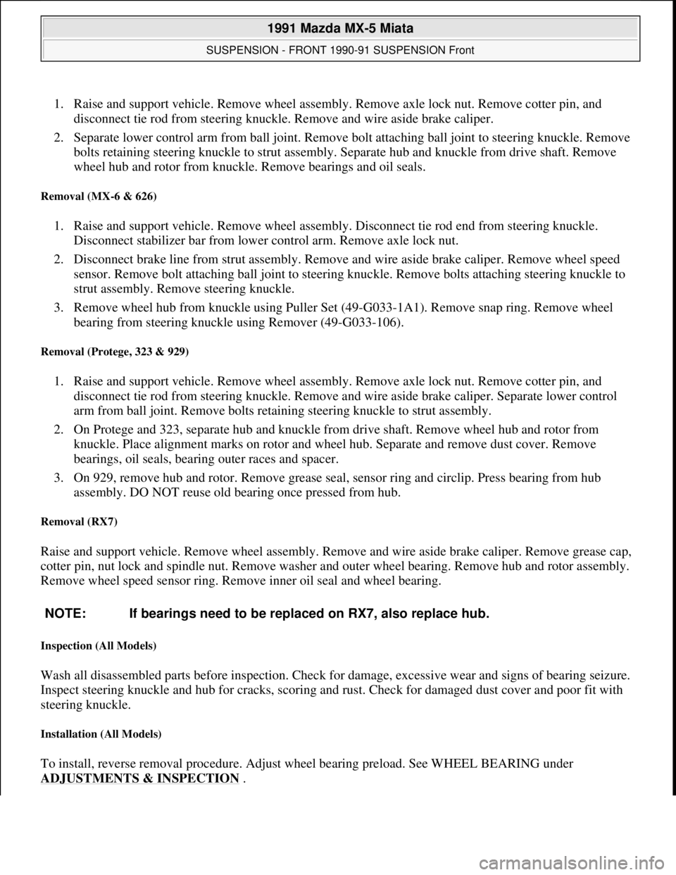
1. Raise and support vehicle. Remove wheel assembly. Remove axle lock nut. Remove cotter pin, and
disconnect tie rod from steering knuckle. Remove and wire aside brake caliper.
2. Separate lower control arm from ball joint. Remove bolt attaching ball joint to steering knuckle. Remove
bolts retaining steering knuckle to strut assembly. Separate hub and knuckle from drive shaft. Remove
wheel hub and rotor from knuckle. Remove bearings and oil seals.
Removal (MX-6 & 626)
1. Raise and support vehicle. Remove wheel assembly. Disconnect tie rod end from steering knuckle.
Disconnect stabilizer bar from lower control arm. Remove axle lock nut.
2. Disconnect brake line from strut assembly. Remove and wire aside brake caliper. Remove wheel speed
sensor. Remove bolt attaching ball joint to steering knuckle. Remove bolts attaching steering knuckle to
strut assembly. Remove steering knuckle.
3. Remove wheel hub from knuckle using Puller Set (49-G033-1A1). Remove snap ring. Remove wheel
bearing from steering knuckle using Remover (49-G033-106).
Removal (Protege, 323 & 929)
1. Raise and support vehicle. Remove wheel assembly. Remove axle lock nut. Remove cotter pin, and
disconnect tie rod from steering knuckle. Remove and wire aside brake caliper. Separate lower control
arm from ball joint. Remove bolts retaining steering knuckle to strut assembly.
2. On Protege and 323, separate hub and knuckle from drive shaft. Remove wheel hub and rotor from
knuckle. Place alignment marks on rotor and wheel hub. Separate and remove dust cover. Remove
bearings, oil seals, bearing outer races and spacer.
3. On 929, remove hub and rotor. Remove grease seal, sensor ring and circlip. Press bearing from hub
assembly. DO NOT reuse old bearing once pressed from hub.
Removal (RX7)
Raise and support vehicle. Remove wheel assembly. Remove and wire aside brake caliper. Remove grease cap,
cotter pin, nut lock and spindle nut. Remove washer and outer wheel bearing. Remove hub and rotor assembly.
Remove wheel speed sensor ring. Remove inner oil seal and wheel bearing.
Inspection (All Models)
Wash all disassembled parts before inspection. Check for damage, excessive wear and signs of bearing seizure.
Inspect steering knuckle and hub for cracks, scoring and rust. Check for damaged dust cover and poor fit with
steering knuckle.
Installation (All Models)
To install, reverse removal procedure. Adjust wheel bearing preload. See WHEEL BEARING under
ADJUSTMENTS & INSPECTION
. NOTE: If bearings need to be replaced on RX7, also replace hub.
1991 Mazda MX-5 Miata
SUSPENSION - FRONT 1990-91 SUSPENSION Front
Microsoft
Sunday, July 05, 2009 2:08:54 PMPage 7 © 2005 Mitchell Repair Information Company, LLC.
Page 311 of 392

Lower Control Arm-To-Frame54-69 (73-93)
Lug Nuts65-87 (88-118)
Stabilizer Bar Bolts (Frame)13-19 (18-26)
Stabilizer Bar Link Bolts27-40 (36-54)
Shock Absorber Assembly-To-Body Nuts21-27 (29-36)
Shock Absorber Lower Bolt54-69 (73-93)
Shock Absorber Lock Nut23-34 (31-46)
Tie Rod-To-Knuckle Nut21-32 (29-44)
Upper Ball Joint-To-Knuckle Nut30-46 (41-62)
Upper Control Arm-To-Frame87-102 (118-138)
MPV
Ball Joint-To-Lower Control Arm Bolt (4WD)75-101 (102-137)
Ball Joint-To-Lower Control Arm Nut (4WD)94-127 (128-172)
Brake Caliper Bracket Bolts65-80 (88-108)
Drive Axle Lock Nut131-173 (177-235)
Lower Control Arm-To-Frame (2WD)94-108 (127-146)
Lower Control Arm-To-Frame (4WD)101-127 (137-172)
Lug Nuts65-87 (88-118)
Stabilizer Bar Bolts (Frame) (2WD)37-45 (50-61)
Stabilizer Bar Bolts (Frame) (4WD)14-19 (19-26)
Strut Assembly Lock Nut47-59 (64-80)
Strut Assembly-To-Body Nuts21-27 (29-36)
Strut Assembly-To-Knuckle Bolt69-86 (93-117)
Strut Rod Body Bushing Bolt61-76 (83-103)
Strut Rod-To-Body Nut108-127 (146-172)
Strut Rod-To-Lower Control Arm76-92 (103-125)
Tie Rod-To-Knuckle Nut44-58 (59-78)
MX-6 & 626
Ball Joint-To-Steering Knuckle Nut27-40 (36-54)
Brake Caliper Bracket Bolts58-72 (78-98)
Drive Axle Lock Nut173-235 (235-319)
Lower Control Arm-To-Frame58-78 (78-106)
Lug Nuts65-87 (88-118)
Stabilizer Bar Bolts (Frame)27-40 (36-54)
Strut Assembly Lock Nut47-59 (64-80)
Strut Assembly-To-Body Nuts34-46 (46-63)
Strut Assembly-To-Knuckle Bolt69-86 (93-117)
Tie Rod-To-Knuckle Nut31-42 (42-57)
Wheel Speed Sensor Bolt12-17 (16-23)
Protege & 323
Ball Joint-To-Lower Control Arm Nut69-86 (93-117)
1991 Mazda MX-5 Miata
SUSPENSION - FRONT 1990-91 SUSPENSION Front
Microsoft
Sunday, July 05, 2009 2:08:54 PMPage 13 © 2005 Mitchell Repair Information Company, LLC.
Page 352 of 392

SUSPENSION - REAR
1991 SUSPENSION Rear
DESCRIPTION
Rear suspension consists of MacPherson-type struts, crossmember, upper and lower arms and stabilizer bar with
control link. Upper and lower arms attach to crossmember and knuckle. A stabilizer bar with control link is
mounted to lower arm and crossmember. Rear wheel alignment is adjusted by turning adjusting cams on lower
arm.
ADJUSTMENTS & INSPECTION
WHEEL ALIGNMENT SPECIFICATIONS & PROCEDURES
See WHEEL ALIGNMENT SPECIFICATIONS AND PROCEDURES article in the WHEEL ALIGNMENT
section.
WHEEL BEARING
Raise vehicle and support. Remove wheel assembly. Remove caliper assembly and wire aside. Remove brake
rotor. Attach dial indicator to axle hub and measure bearing play. Maximum bearing play is .002" (.05 mm). If
play exceeds specification, check rear axle lock nut torque or replace wheel bearing.
REMOVAL & INSTALLATION
WHEEL BEARING
Removal
1. Raise and support vehicle. Remove wheel assembly. Remove drive axle lock nut. Remove brake caliper
assembly, and wire aside. Remove screws and rotor. Disconnect ABS speed sensor. Remove knuckle
assembly from upper and lower arms.
2. Using a press, Installer (49-G030-727) and Puller (49-F026-103), remove hub from knuckle. Remove
snap ring from knuckle. Using a press, installer and Puller (49-0636-145), remove wheel bearing inner
race from hub. Remove wheel bearing outer race from knuckle using a press and Adapter (49-F027-005).
Inspection
Check wheel hub and knuckle for cracks and damage. Check dust cover for deformation. Check bearing for
excessive wear or seizure.
Installation
Press new wheel bearing into knuckle using Installer (49-F027-007) and Adapter (49-F027-009). Press hub into
knuckle using installer. To install, reverse removal procedure. Tighten drive axle lock nut to specification. Stake
1991 Mazda MX-5 Miata
SUSPENSION - REAR 1991 SUSPENSION Rear
1991 Mazda MX-5 Miata
SUSPENSION - REAR 1991 SUSPENSION Rear
Microsoft
Sunday, July 05, 2009 2:09:35 PMPage 1 © 2005 Mitchell Repair Information Company, LLC.
Microsoft
Sunday, July 05, 2009 2:09:39 PMPage 1 © 2005 Mitchell Repair Information Company, LLC.