ECU MAZDA MIATA 1991 Factory Service Manual
[x] Cancel search | Manufacturer: MAZDA, Model Year: 1991, Model line: MIATA, Model: MAZDA MIATA 1991Pages: 392, PDF Size: 29.45 MB
Page 155 of 392
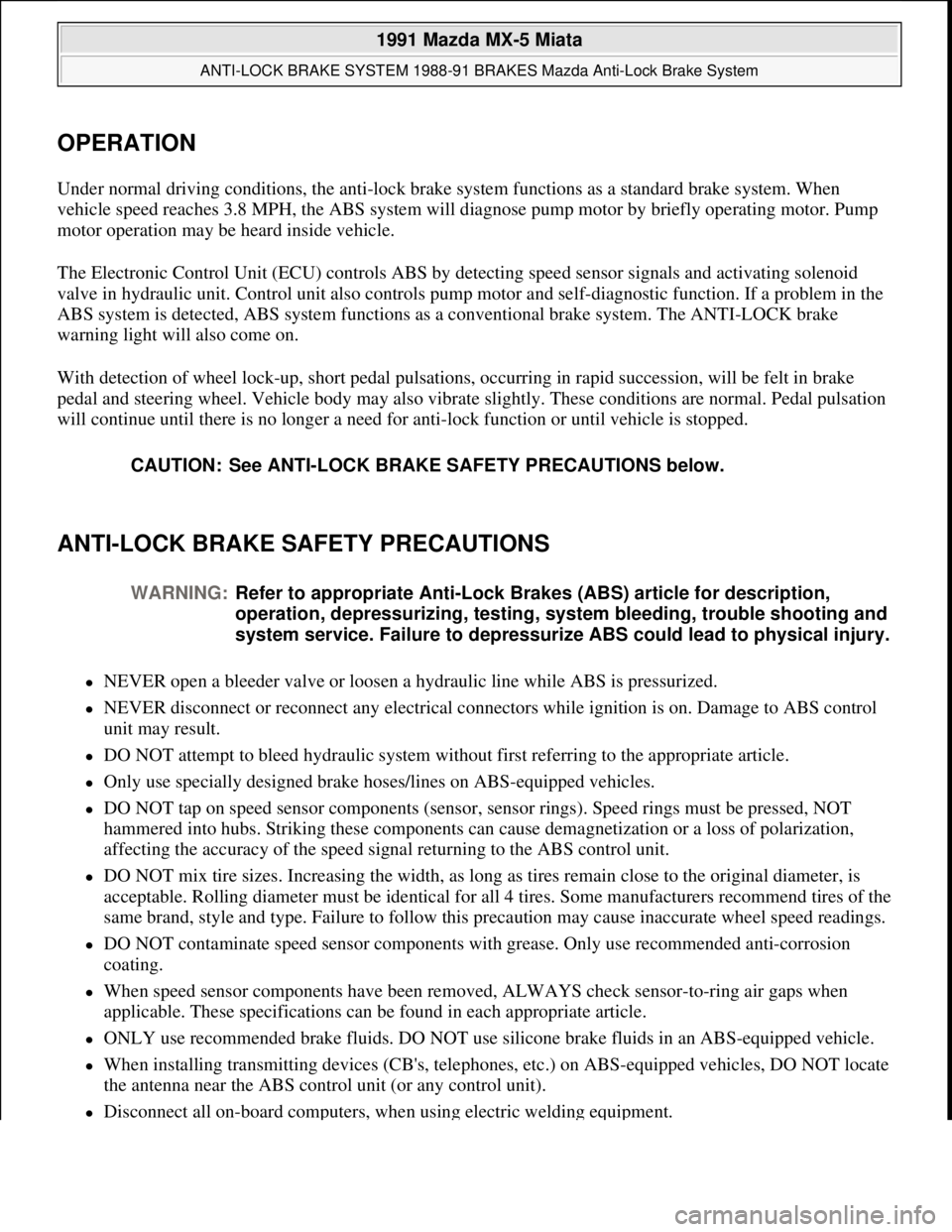
OPERATION
Under normal driving conditions, the anti-lock brake system functions as a standard brake system. When
vehicle speed reaches 3.8 MPH, the ABS system will diagnose pump motor by briefly operating motor. Pump
motor operation may be heard inside vehicle.
The Electronic Control Unit (ECU) controls ABS by detecting speed sensor signals and activating solenoid
valve in hydraulic unit. Control unit also controls pump motor and self-diagnostic function. If a problem in the
ABS system is detected, ABS system functions as a conventional brake system. The ANTI-LOCK brake
warning light will also come on.
With detection of wheel lock-up, short pedal pulsations, occurring in rapid succession, will be felt in brake
pedal and steering wheel. Vehicle body may also vibrate slightly. These conditions are normal. Pedal pulsation
will continue until there is no longer a need for anti-lock function or until vehicle is stopped.
ANTI-LOCK BRAKE SAFETY PRECAUTIONS
NEVER open a bleeder valve or loosen a hydraulic line while ABS is pressurized.
NEVER disconnect or reconnect any electrical connectors while ignition is on. Damage to ABS control
unit may result.
DO NOT attempt to bleed hydraulic system without first referring to the appropriate article.
Only use specially designed brake hoses/lines on ABS-equipped vehicles.
DO NOT tap on speed sensor components (sensor, sensor rings). Speed rings must be pressed, NOT
hammered into hubs. Striking these components can cause demagnetization or a loss of polarization,
affecting the accuracy of the speed signal returning to the ABS control unit.
DO NOT mix tire sizes. Increasing the width, as long as tires remain close to the original diameter, is
acceptable. Rolling diameter must be identical for all 4 tires. Some manufacturers recommend tires of the
same brand, style and type. Failure to follow this precaution may cause inaccurate wheel speed readings.
DO NOT contaminate speed sensor components with grease. Only use recommended anti-corrosion
coating.
When speed sensor components have been removed, ALWAYS check sensor-to-ring air gaps when
applicable. These specifications can be found in each appropriate article.
ONLY use recommended brake fluids. DO NOT use silicone brake fluids in an ABS-equipped vehicle.
When installing transmitting devices (CB's, telephones, etc.) on ABS-equipped vehicles, DO NOT locate
the antenna near the ABS control unit (or any control unit).
Disconnect all on-board computers, when using electric welding equipment. CAUTION: See ANTI-LOCK BRAKE SAFETY PRECAUTIONS below.
WARNING:Refer to appropriate Anti-Lock Brakes (ABS) article for description,
operation, depressurizing, testing, system bleeding, trouble shooting and
system service. Failure to depressurize ABS could lead to physical injury.
1991 Mazda MX-5 Miata
ANTI-LOCK BRAKE SYSTEM 1988-91 BRAKES Mazda Anti-Lock Brake System
Microsoft
Sunday, July 05, 2009 2:17:31 PMPage 3 © 2005 Mitchell Repair Information Company, LLC.
Page 166 of 392
WHEEL SPEED SENSOR ROTORS
Inspection
Perform a comprehensive visual inspection of sensor rotor. If any damage is noted, replace sensor rotor. Sensor
rotors are attached to wheel hubs.
REMOVAL & INSTALLATION
HYDRAULIC UNIT
Removal
Remove hydraulic lines from unit. Disconnect hydraulic unit connectors. Remove nuts securing unit. Remove
hydraulic unit.
Bleeding Hydraulic Unit
Before bleeding hydraulic unit, bleed brake system in appropriate sequence. See BRAKE LINE BLEEDING
SEQUENCE TABLE under BLEEDING BRAKE SYSTEM. Bleed hydraulic unit by opening bleeder screw on
unit. See Fig. 12
.
Installation
To install, reverse removal procedure. Tighten mounting bolts to specification. See TORQUE
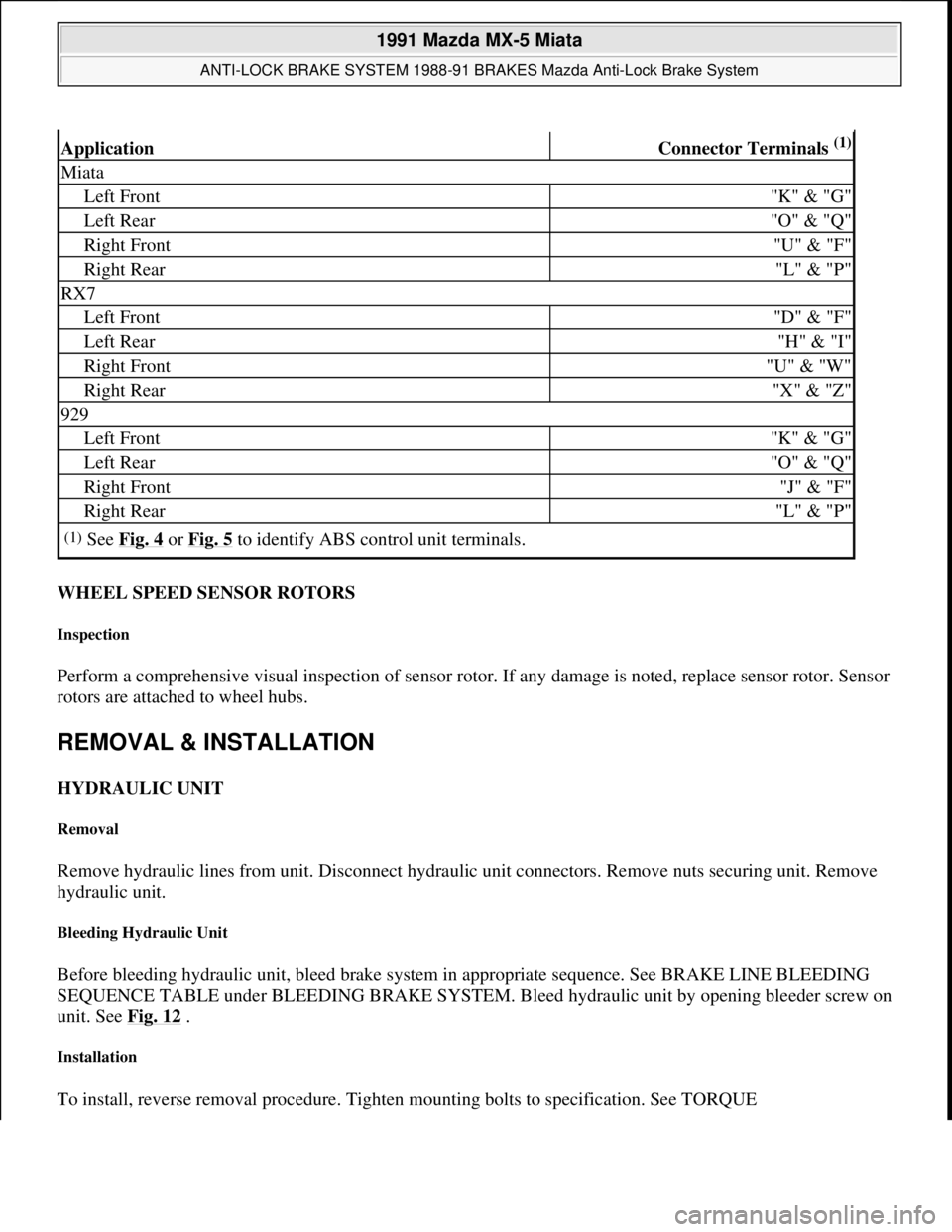
ApplicationConnector Terminals (1)
Miata
Left Front"K" & "G"
Left Rear"O" & "Q"
Right Front"U" & "F"
Right Rear"L" & "P"
RX7
Left Front"D" & "F"
Left Rear"H" & "I"
Right Front"U" & "W"
Right Rear"X" & "Z"
929
Left Front"K" & "G"
Left Rear"O" & "Q"
Right Front"J" & "F"
Right Rear"L" & "P"
(1)See Fig. 4 or Fig. 5 to identify ABS control unit terminals.
1991 Mazda MX-5 Miata
ANTI-LOCK BRAKE SYSTEM 1988-91 BRAKES Mazda Anti-Lock Brake System
Microsoft
Sunday, July 05, 2009 2:17:32 PMPage 14 © 2005 Mitchell Repair Information Company, LLC.
Page 208 of 392
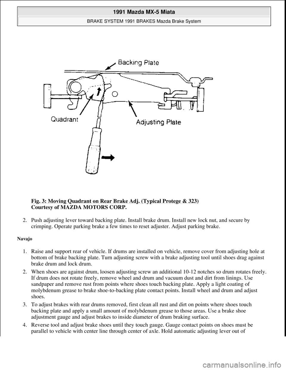
Fig. 3: Moving Quadrant on Rear Brake Adj. (Typical Protege & 323)
Courtesy of MAZDA MOTORS CORP.
2. Push adjusting lever toward backing plate. Install brake drum. Install new lock nut, and secure by
crimping. Operate parking brake a few times to reset adjuster. Adjust parking brake.
Navajo
1. Raise and support rear of vehicle. If drums are installed on vehicle, remove cover from adjusting hole at
bottom of brake backing plate. Turn adjusting screw with a brake adjusting tool until shoes drag against
brake drum and lock drum.
2. When shoes are against drum, loosen adjusting screw an additional 10-12 notches so drum rotates freely.
If drum does not rotate freely, remove wheel and drum and vacuum dust and dirt from linings. Use
sandpaper and remove rust from points where shoes touch backing plate. Apply a light coating of
molybdenum grease to brake shoe-to-backing plate contact points. Install wheel and drum and adjust
shoes.
3. To adjust brakes with rear drums removed, first clean all rust and dirt on points where shoes touch
backing plate and apply a small amount of molybdenum grease to those areas. Use a brake shoe
adjustment gauge and adjust brakes to inside diameter of drum braking surface.
4. Reverse tool and adjust brake shoes until they touch gauge. Gauge contact points on shoes must be
parallel to vehicle with center line throu
gh center of axle. Hold automatic adjusting lever out of
1991 Mazda MX-5 Miata
BRAKE SYSTEM 1991 BRAKES Mazda Brake System
Microsoft
Sunday, July 05, 2009 2:18:08 PMPage 5 © 2005 Mitchell Repair Information Company, LLC.
Page 227 of 392
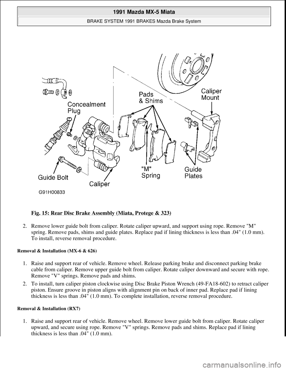
Fig. 15: Rear Disc Brake Assembly (Miata, Protege & 323)
2. Remove lower guide bolt from caliper. Rotate caliper upward, and support using rope. Remove "M"
spring. Remove pads, shims and guide plates. Replace pad if lining thickness is less than .04" (1.0 mm).
To install, reverse removal procedure.
Removal & Installation (MX-6 & 626)
1. Raise and support rear of vehicle. Remove wheel. Release parking brake and disconnect parking brake
cable from caliper. Remove upper guide bolt from caliper. Rotate caliper downward and secure with rope.
Remove "V" springs. Remove pads and shims.
2. To install, turn caliper piston clockwise using Disc Brake Piston Wrench (49-FA18-602) to retract caliper
piston. Ensure groove in piston aligns with alignment pin on back of inner pad. Replace pad if lining
thickness is less than .04" (1.0 mm). To complete installation, reverse removal procedure.
Removal & Installation (RX7)
1. Raise and support rear of vehicle. Remove wheel. Remove lower guide bolt from caliper. Rotate caliper
upward, and secure using rope. Remove "V" springs. Remove pads and shims. Replace pad if lining
thickness is less than .04" (1.0 mm).
1991 Mazda MX-5 Miata
BRAKE SYSTEM 1991 BRAKES Mazda Brake System
Microsoft
Sunday, July 05, 2009 2:18:08 PMPage 24 © 2005 Mitchell Repair Information Company, LLC.
Page 228 of 392
2. To install, turn caliper piston clockwise using Disc Brake Piston Wrench (49-FA18-602) to retract caliper
piston. Ensure groove in piston aligns with alignment pin on back of inner pad. To install remaining
components, reverse removal procedure.
Removal & Installation (929)
Raise and support rear of vehicle. Remove wheel. Remove lower guide bolt from caliper. Rotate caliper upward
and secure with rope. Remove pads and shims. Replace pad if lining thickness is less than .08" (2.0 mm). To
install, reverse removal procedure.
REAR BRAKE CALIPER
Removal & Installation
1. Raise and support rear of vehicle. On all models except 929, release parking brake and disconnect parking
brake cable from caliper. On all models, disconnect brake hose from caliper.
2. On Miata, Protege and 323, remove manual adjustment gear concealment plug from caliper. See Fig. 15
.
Insert an appropriate size Allen wrench through hole and turn manual adjustment gear counterclockwise
to retract caliper piston.
3. On all models, remove lower guide bolt from caliper. Rotate caliper upward. Pull caliper toward center of
vehicle to slide it off of caliper mount. To install, reverse removal procedure. Bleed hydraulic system.
REAR BRAKE ROTOR
Removal & Installation (Miata, Protege, RX7, 323 & 929)
Remove rear brake caliper. Remove rotor-to-hub screws. Remove rotor. Machine rotor if lateral runout exceeds
specification. Replace rotor if measured thickness is less than specified minimum thickness. See DISC BRAKE
SPECIFICATIONS at end of article. To install, reverse removal procedure.
Removal & Installation (MX-6 & 626)
1. Remove rear caliper, and wire aside. Remove grease cap. Remove lock nut. Remove rotor. Machine rotor
if lateral runout exceeds specification. Replace rotor if measured thickness is less than specified minimum
thickness. See DISC BRAKE SPECIFICATIONS
at end of article.
2. To install, reverse removal procedure. Tighten lock nut to 73-131 ft. lbs. (99-178 N.m). Check end play at
grease cap. If end play exceeds .008" (.20 mm), replace wheel bearings.
REAR BRAKE SHOES
Removal (B2200, B2600i & MPV)
With brake drum removed, remove brake shoe return springs, retaining springs and guide pins. See Fig. 16 or
Fig. 17
. Remove brake shoes. Remove parking brake strut, and disconnect parking brake cable from operating
lever of secondar
y shoe. Minimum lining thickness is .04" (1 mm).
1991 Mazda MX-5 Miata
BRAKE SYSTEM 1991 BRAKES Mazda Brake System
Microsoft
Sunday, July 05, 2009 2:18:08 PMPage 25 © 2005 Mitchell Repair Information Company, LLC.
Page 230 of 392
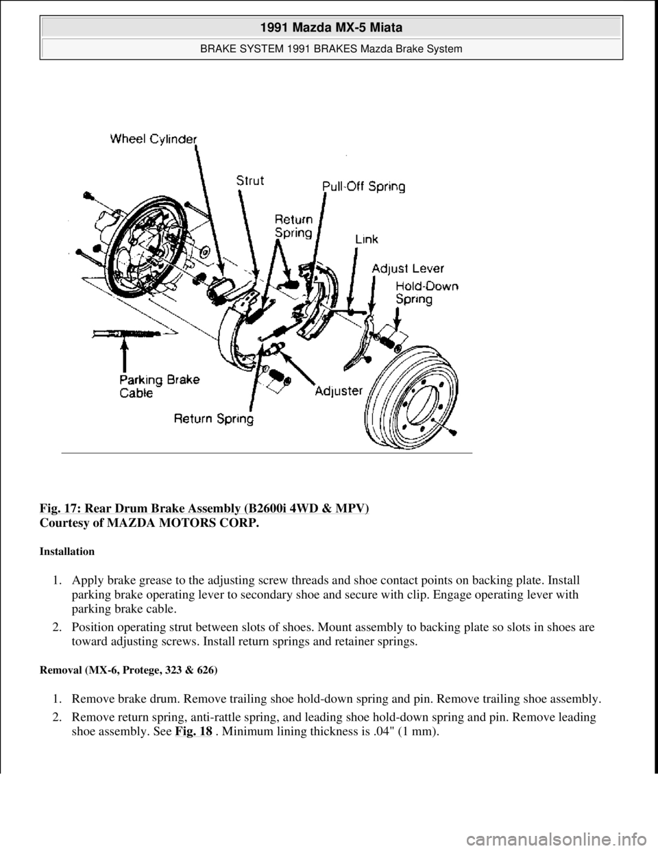
Fig. 17: Rear Drum Brake Assembly (B2600i 4WD & MPV)
Courtesy of MAZDA MOTORS CORP.
Installation
1. Apply brake grease to the adjusting screw threads and shoe contact points on backing plate. Install
parking brake operating lever to secondary shoe and secure with clip. Engage operating lever with
parking brake cable.
2. Position operating strut between slots of shoes. Mount assembly to backing plate so slots in shoes are
toward adjusting screws. Install return springs and retainer springs.
Removal (MX-6, Protege, 323 & 626)
1. Remove brake drum. Remove trailing shoe hold-down spring and pin. Remove trailing shoe assembly.
2. Remove return spring, anti-rattle spring, and leading shoe hold-down spring and pin. Remove leading
shoe assembly. See Fig. 18
. Minimum lining thickness is .04" (1 mm).
1991 Mazda MX-5 Miata
BRAKE SYSTEM 1991 BRAKES Mazda Brake System
Microsoft
Sunday, July 05, 2009 2:18:08 PMPage 27 © 2005 Mitchell Repair Information Company, LLC.
Page 242 of 392
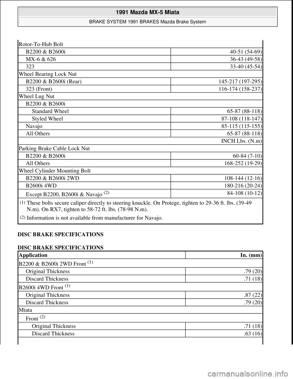
DISC BRAKE SPECIFICATIONS
DISC BRAKE SPECIFICATIONS
Rotor-To-Hub Bolt
B2200 & B2600i40-51 (54-69)
MX-6 & 62636-43 (49-58)
32333-40 (45-54)
Wheel Bearing Lock Nut
B2200 & B2600i (Rear)145-217 (197-295)
323 (Front)116-174 (158-237)
Wheel Lug Nut
B2200 & B2600i
Standard Wheel65-87 (88-118)
Styled Wheel87-108 (118-147)
Navajo85-115 (115-155)
All Others65-87 (88-118)
INCH Lbs. (N.m)
Parking Brake Cable Lock Nut
B2200 & B2600i60-84 (7-10)
All Others168-252 (19-29)
Wheel Cylinder Mounting Bolt
B2200 & B2600i 2WD108-144 (12-16)
B2600i 4WD180-216 (20-24)
Except B2200, B2600i & Navajo (2) 84-108 (10-12)
(1)These bolts secure caliper directly to steering knuckle. On Protege, tighten to 29-36 ft. lbs. (39-49
N.m). On RX7, tighten to 58-72 ft. lbs. (78-98 N.m).
(2)Information is not available from manufacturer for Navajo.
ApplicationIn. (mm)
B2200 & B2600i 2WD Front (1)
Original Thickness.79 (20)
Discard Thickness.71 (18)
B2600i 4WD Front (1)
Original Thickness.87 (22)
Discard Thickness.79 (20)
Miata
Front (2)
Original Thickness.71 (18)
Discard Thickness.63 (16)
1991 Mazda MX-5 Miata
BRAKE SYSTEM 1991 BRAKES Mazda Brake System
Microsoft
Sunday, July 05, 2009 2:18:09 PMPage 39 © 2005 Mitchell Repair Information Company, LLC.
Page 272 of 392
reassembly purposes. Separate ring gear from gear case. On standard differentials, remove knock pin.
Remove pinion shaft, pinion gears, thrust washers and side gears. See Fig. 8
.
2. On Limited Slip Differentials (LSD) models, gradually loosen attaching screws until distance between
left and right half of differential case is about 0.12" (3 mm). On all models, mark differential halves for
reassembly reference.
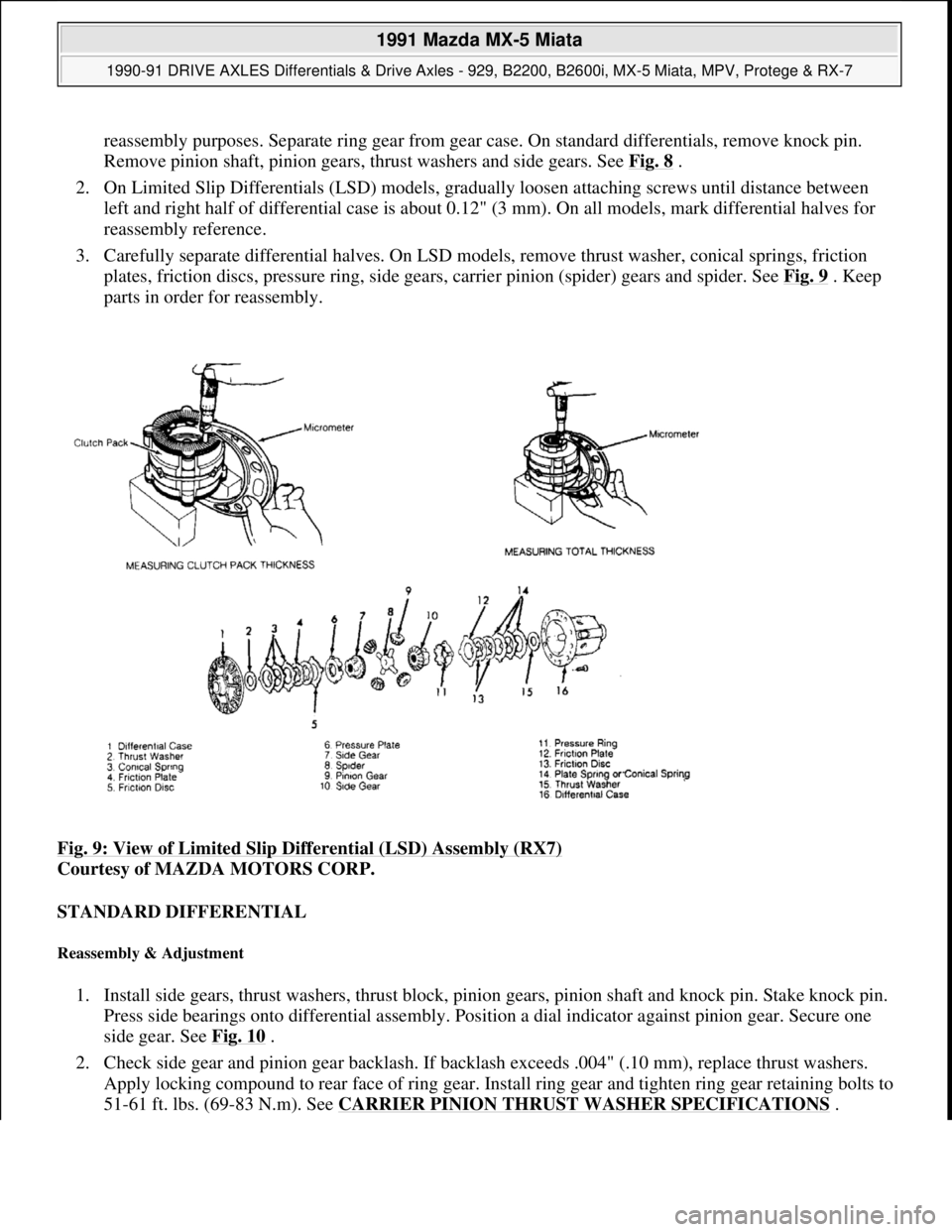
3. Carefully separate differential halves. On LSD models, remove thrust washer, conical springs, friction
plates, friction discs, pressure ring, side gears, carrier pinion (spider) gears and spider. See Fig. 9
. Keep
parts in order for reassembly.
Fig. 9: View of Limited Slip Differential (LSD) Assembly (RX7)
Courtesy of MAZDA MOTORS CORP.
STANDARD DIFFERENTIAL
Reassembly & Adjustment
1. Install side gears, thrust washers, thrust block, pinion gears, pinion shaft and knock pin. Stake knock pin.
Press side bearings onto differential assembly. Position a dial indicator against pinion gear. Secure one
side gear. See Fig. 10
.
2. Check side gear and pinion gear backlash. If backlash exceeds .004" (.10 mm), replace thrust washers.
Apply locking compound to rear face of ring gear. Install ring gear and tighten ring gear retaining bolts to
51-61 ft. lbs. (69-83 N.m). See CARRIER PINION THRUST WASHER SPECIFICATIONS
.
1991 Mazda MX-5 Miata
1990-91 DRIVE AXLES Differentials & Drive Axles - 929, B2200, B2600i, MX-5 Miata, MPV, Protege & RX-7
Microsoft
Sunday, July 05, 2009 2:17:01 PMPage 14 © 2005 Mitchell Repair Information Company, LLC.
Page 274 of 392
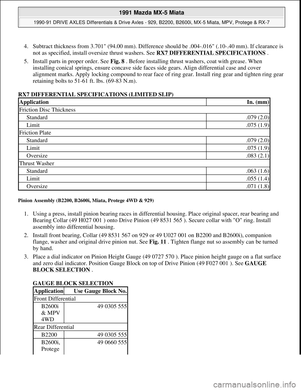
4. Subtract thickness from 3.701" (94.00 mm). Difference should be .004-.016" (.10-.40 mm). If clearance is
not as specified, install oversize thrust washers. See RX7 DIFFERENTIAL SPECIFICATIONS
.
5. Install parts in proper order. See Fig. 8
. Before installing thrust washers, coat with grease. When
installing conical springs, ensure concave side faces side gears. Align differential case and cover
alignment marks. Apply locking compound to rear face of ring gear. Install ring gear and tighten ring gear
retaining bolts to 51-61 ft. lbs. (69-83 N.m).
RX7 DIFFERENTIAL SPECIFICATIONS (LIMITED SLIP)
Pinion Assembly (B2200, B2600i, Miata, Protege 4WD & 929)
1. Using a press, install pinion bearing races in differential housing. Place original spacer, rear bearing and
Bearing Collar (49 H027 001 ) onto Drive Pinion (49 8531 565 ). Secure collar with "O" ring. Install
assembly into differential housing.
2. Install front bearing, Collar (49 8531 567 on 929 or 49 U027 001 on B2200 and B2600i), companion
flange, washer and original drive pinion nut. See Fig. 11
. Tighten flange nut so assembly can be turned
by hand.
3. Place a dial indicator on Pinion Height Gauge (49 0727 570 ). Place pinion height gauge on a flat surface
and zero dial indicator. Position Gauge Block on top of Drive Pinion (49 F027 001 ). See GAUGE
BLOCK SELECTION .
GAUGE BLOCK SELECTION
ApplicationIn. (mm)
Friction Disc Thickness
Standard.079 (2.0)
Limit.075 (1.9)
Friction Plate
Standard.079 (2.0)
Limit.075 (1.9)
Oversize.083 (2.1)
Thrust Washer
Standard.063 (1.6)
Limit.055 (1.4)
Oversize.071 (1.8)
ApplicationUse Gauge Block No.
Front Differential
B2600i
& MPV
4WD49 0305 555
Rear Differential
B220049 0305 555
B2600i,
Protege 49 0660 555
1991 Mazda MX-5 Miata
1990-91 DRIVE AXLES Differentials & Drive Axles - 929, B2200, B2600i, MX-5 Miata, MPV, Protege & RX-7
Microsoft
Sunday, July 05, 2009 2:17:01 PMPage 16 © 2005 Mitchell Repair Information Company, LLC.
Page 294 of 392
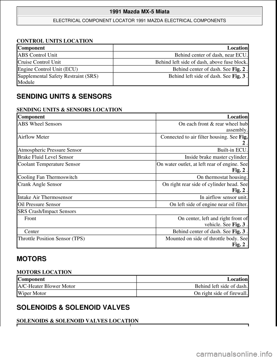
CONTROL UNITS LOCATION
SENDING UNITS & SENSORS
SENDING UNITS & SENSORS LOCATION
MOTORS
MOTORS LOCATION
SOLENOIDS & SOLENOID VALVES
SOLENOIDS & SOLENOID VALVES LOCATION
ComponentLocation
ABS Control UnitBehind center of dash, near ECU.
Cruise Control UnitBehind left side of dash, above fuse block.
Engine Control Unit (ECU)Behind center of dash. See Fig. 2 .
Supplemental Safety Restraint (SRS)
ModuleBehind left side of dash. See Fig. 3 .
ComponentLocation
ABS Wheel SensorsOn each front & rear wheel hub
assembly.
Airflow MeterConnected to air filter housing. See Fig.
2 .
Atmospheric Pressure SensorBuilt-in ECU.
Brake Fluid Level SensorInside brake master cylinder.
Coolant Temperature SensorOn water outlet, at left rear of engine. See
Fig. 2
.
Cooling Fan ThermoswitchOn thermostat housing.
Crank Angle SensorOn right rear side of cylinder head. See
Fig. 2
.
Intake Air ThermosensorIn airflow sensor unit.
Oil Pressure SensorOn left side of engine near oil filter.
SRS Crash/Impact Sensors
FrontOn center, left and right front of
vehicle. See Fig. 3
.
CenterBehind center of dash. See Fig. 3 .
Throttle Position Sensor (TPS)Mounted on side of throttle body. See
Fig. 2
.
ComponentLocation
A/C-Heater Blower MotorBehind left side of dash.
Wiper MotorOn right side of firewall.
1991 Mazda MX-5 Miata
ELECTRICAL COMPONENT LOCATOR 1991 MAZDA ELECTRICAL COMPONENTS
Microsoft
Sunday, July 05, 2009 2:15:23 PMPage 2 © 2005 Mitchell Repair Information Company, LLC.