MAZDA MODEL TRIBUTE 2003 Owners Manual (in English)
Manufacturer: MAZDA, Model Year: 2003, Model line: MODEL TRIBUTE, Model: MAZDA MODEL TRIBUTE 2003Pages: 248, PDF Size: 2.5 MB
Page 151 of 248

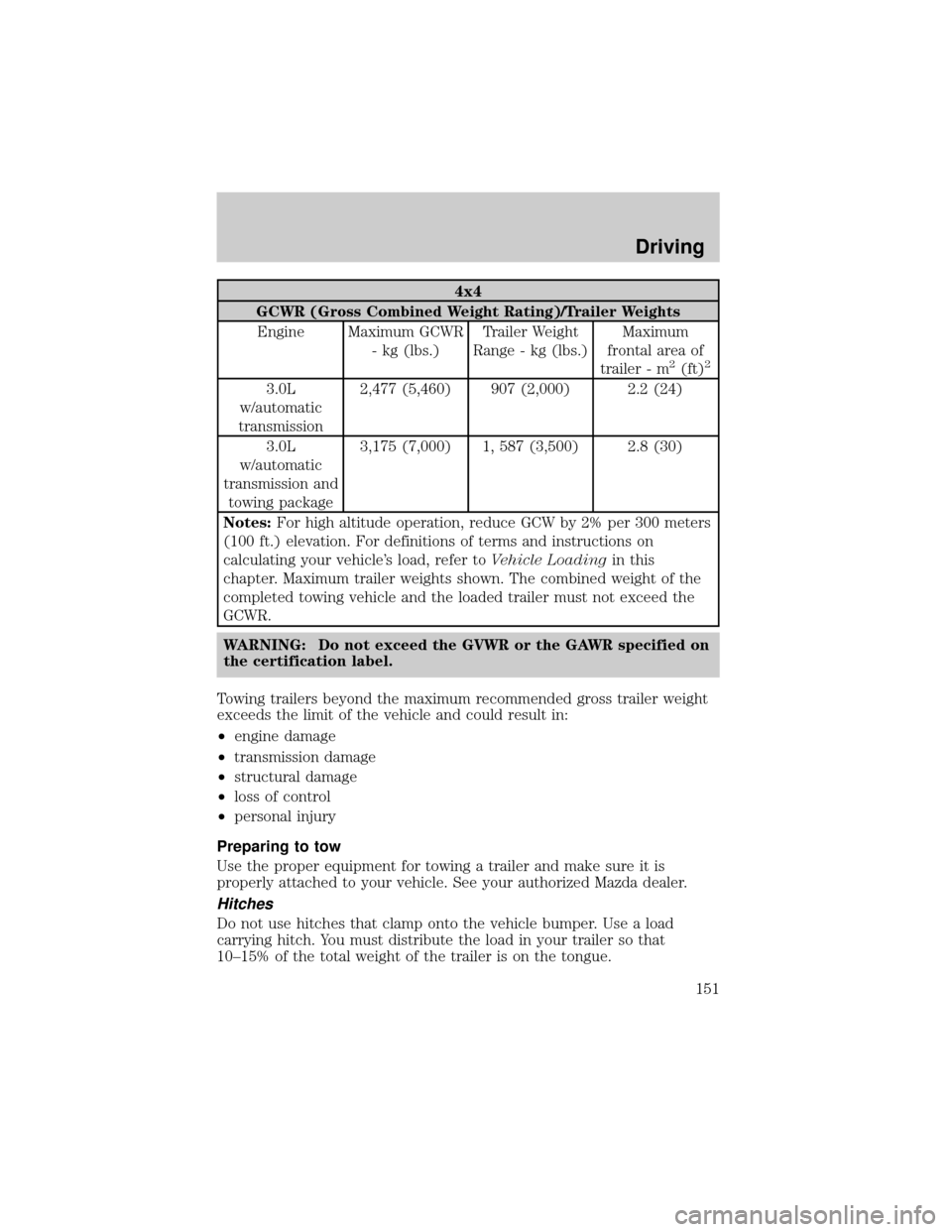
4x4
GCWR (Gross Combined Weight Rating)/Trailer Weights
Engine Maximum GCWR
- kg (lbs.)Trailer Weight
Range - kg (lbs.)Maximum
frontal area of
trailer - m
2(ft)2
3.0L
w/automatic
transmission2,477 (5,460) 907 (2,000) 2.2 (24)
3.0L
w/automatic
transmission and
towing package3,175 (7,000) 1, 587 (3,500) 2.8 (30)
Notes:For high altitude operation, reduce GCW by 2% per 300 meters
(100 ft.) elevation. For definitions of terms and instructions on
calculating your vehicle's load, refer toVehicle Loadingin this
chapter. Maximum trailer weights shown. The combined weight of the
completed towing vehicle and the loaded trailer must not exceed the
GCWR.
WARNING: Do not exceed the GVWR or the GAWR specified on
the certification label.
Towing trailers beyond the maximum recommended gross trailer weight
exceeds the limit of the vehicle and could result in:
²engine damage
²transmission damage
²structural damage
²loss of control
²personal injury
Preparing to tow
Use the proper equipment for towing a trailer and make sure it is
properly attached to your vehicle. See your authorized Mazda dealer.
Hitches
Do not use hitches that clamp onto the vehicle bumper. Use a load
carrying hitch. You must distribute the load in your trailer so that
10±15% of the total weight of the trailer is on the tongue.
Driving
151
Page 152 of 248

Safety chains
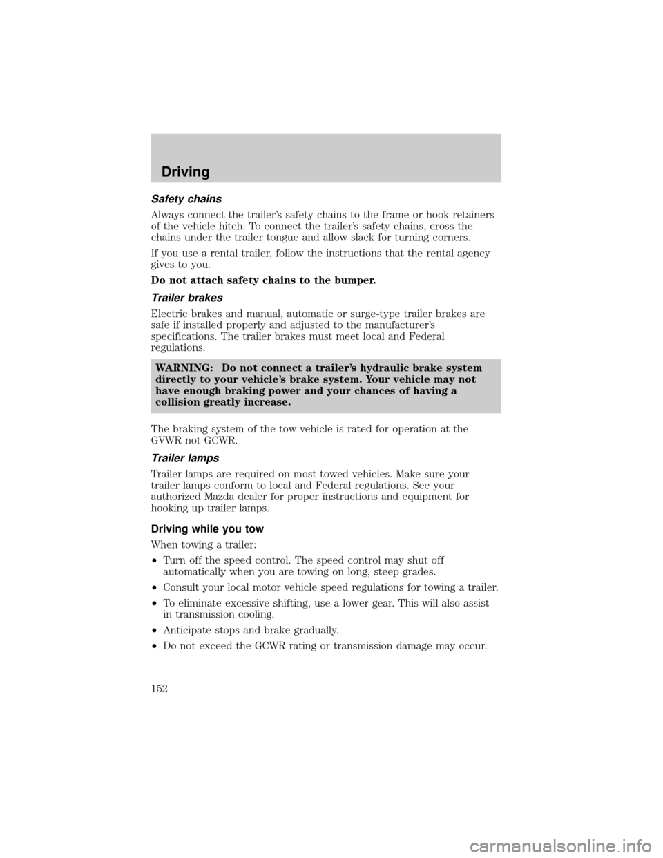
Always connect the trailer's safety chains to the frame or hook retainers
of the vehicle hitch. To connect the trailer's safety chains, cross the
chains under the trailer tongue and allow slack for turning corners.
If you use a rental trailer, follow the instructions that the rental agency
gives to you.
Do not attach safety chains to the bumper.
Trailer brakes
Electric brakes and manual, automatic or surge-type trailer brakes are
safe if installed properly and adjusted to the manufacturer's
specifications. The trailer brakes must meet local and Federal
regulations.
WARNING: Do not connect a trailer's hydraulic brake system
directly to your vehicle's brake system. Your vehicle may not
have enough braking power and your chances of having a
collision greatly increase.
The braking system of the tow vehicle is rated for operation at the
GVWR not GCWR.
Trailer lamps
Trailer lamps are required on most towed vehicles. Make sure your
trailer lamps conform to local and Federal regulations. See your
authorized Mazda dealer for proper instructions and equipment for
hooking up trailer lamps.
Driving while you tow
When towing a trailer:
²Turn off the speed control. The speed control may shut off
automatically when you are towing on long, steep grades.
²Consult your local motor vehicle speed regulations for towing a trailer.
²To eliminate excessive shifting, use a lower gear. This will also assist
in transmission cooling.
²Anticipate stops and brake gradually.
²Do not exceed the GCWR rating or transmission damage may occur.
Driving
152
Page 153 of 248

Servicing after towing
If you tow a trailer for long distances, your vehicle will require more
frequent service intervals. Refer to the ªScheduled Maintenanceº section
for more information.
Trailer towing tips
²Practice turning, stopping and backing up before starting on a trip to
get the feel of the vehicle trailer combination. When turning, make
wider turns so the trailer wheels will clear curbs and other obstacles.
²Allow more distance for stopping with a trailer attached.
²The trailer tongue weight should be 10±15% of the loaded trailer
weight.
²After you have traveled 80 km (50 miles), thoroughly check your
hitch, electrical connections and trailer wheel lug nuts.
²To aid in engine/transmission cooling and A/C efficiency during hot
weather while stopped in traffic, place the gearshift lever in P (Park)
(automatic transmission) or N (Neutral) (manual transmissions).
²Vehicles with trailers should not be parked on a grade. If you must
park on a grade, place wheel chocks under the trailer's wheels.
Launching or retrieving a boat
When backing down a ramp during boat launching or retrieval,
²Do not allow the static water level to rise above the bottom edge of
the rear bumper.
²Do not allow waves to break higher than 15 cm (6 inches) above the
bottom edge of the rear bumper.
Exceeding these limits may allow water to enter critical vehicle
components, adversely affecting driveability, emissions, reliability
and causing internal transmission damage.
Replace the rear axle lubricant any time the axle has been
submerged in water. Rear axle lubricant quantities are not to be
checked or changed unless a leak is suspected or repair required.
Disconnect the wiring to the trailer before backing the trailer into the
water. Reconnect the wiring to the trailer after the trailer is removed
from the water. Water entering these areas, while connected, could
short-circuit the system.
Driving
153
Page 154 of 248

RECREATIONAL TOWING
An example of ªrecreational towingº is towing your vehicle behind a
motorhome.
If your vehicle is automatic transmission equipped, with a 4x2
(front-wheel drive only) configured powertrain, ªrecreational towingº is
permitted by trailering the vehicle with its front wheels on a dolly. This
protects the transmission's internal mechanical components from
potential lack of lubrication damage.
If your vehicle is manual transaxle equipped and 2WD or 4WD, shifting
the transaxle into neutral permits ªflat-towingº (all wheels on the
ground) for pulling behind a motorhome. Your vehicle may be towed up
to a speed of 120 km/h (75 mph) but you should always obey local speed
limits.
If your vehicle is automatic transaxle equipped and 4WD (all-wheel
drive), ªrecreational towingº is permitted only if the vehicle is trailered
with all four (4) wheels off the ground. Otherwise, no ªrecreational
towingº is permitted.
For other towing requirements, refer toWrecker Towingin the
Roadside emergencieschapter.
Driving
154
Page 155 of 248

HAZARD FLASHER CONTROL
The hazard flasher is located on the
instrument panel by the radio. The
hazard flashers will operate when
the ignition is off.
Push in the flasher control and all front and rear direction signals will
flash. Press the flasher control again to turn them off. Use it when your
vehicle is disabled and is creating a safety hazard for other motorists.
Note:With extended use, the flasher may run down your battery.
FUEL PUMP SHUT-OFF SWITCH
FUEL
RESET
This device stops the electric fuel pump from sending fuel to the engine
when your vehicle has had a substantial jolt.
After an accident, if the engine cranks but does not start, this switch
may have been activated.
This switch is located in the front
passenger's footwell, by the kick
panel access cover.
To reset the switch:
1. Turn the ignition OFF.
2. Check the fuel system for leaks.
3. Remove the kick panel access
cover, located in the front
passenger's footwell.
4. If no leaks are apparent, reset
the switch by pushing in on the
reset button.
5. Turn the ignition ON.
6. Wait a few seconds and return
the key to OFF.
7. Make another check of leaks.
Roadside Emergencies
155
Page 156 of 248

FUSES AND RELAYS
Fuses
If electrical components in the
vehicle are not working, a fuse may
have blown. Blown fuses are
identified by a broken wire within
the fuse. Check the appropriate
fuses before replacing any electrical
components.
Note:Always replace a fuse with one that has the specified amperage
rating. Using a fuse with a higher amperage rating can cause severe wire
damage and could start a fire.
Standard fuse amperage rating and color
COLOR
Fuse
ratingMini
fusesStandard
fusesMaxi
fusesCartridge
maxi
fusesFuse link
cartridge
2A Grey Grey Ð Ð Ð
3A Violet Violet Ð Ð Ð
4A Pink Pink Ð Ð Ð
5A Tan Tan Ð Ð Ð
7.5A Brown Brown Ð Ð Ð
10A Red Red Ð Ð Ð
15A Blue Blue Ð Ð Ð
20A Yellow Yellow Yellow Blue Blue
25A Natural Natural Ð Ð Ð
30A Green Green Green Pink Pink
40A Ð Ð Orange Green Green
50A Ð Ð Red Red Red
60A Ð Ð Blue Ð Yellow
70A Ð Ð Tan Ð Brown
80A Ð Ð Natural Ð Black
Passenger compartment fuse panel
The fuse panel is located below and to the left of the steering wheel by
the brake pedal. Remove the panel cover to access the fuses.
15
Roadside Emergencies
156
Page 157 of 248

To remove a fuse use the fuse puller tool provided on the fuse panel
cover.
The fuses are coded as follows:
Fuse/Relay
LocationFuse Amp
RatingPassenger Compartment Fuse Panel
Description
1 5A Canister vent control solenoid
2 5A Blower relay (coil), Pressure switch to
PCM
3 10A Rear wiper motor, Rear washer motor,
Rear wiper relay (coil)
4 10A Four-wheel drive control module, Cluster
(restraints control warning)
5 5A ABS unit (EVAC & FILL), ASC unit,
Restraints Control Module (RCM), ASC
main SW to ASC unit, Clock spring switch
ACC
12
34
56
78
910
11 12
13 14
15 16
17 18
19 20
21 22
23 24
25 26
27
Roadside Emergencies
157
Page 158 of 248

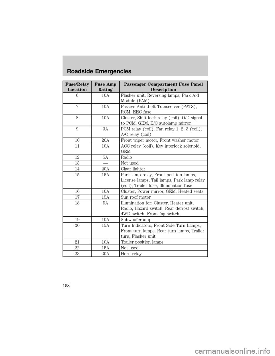
Fuse/Relay
LocationFuse Amp
RatingPassenger Compartment Fuse Panel
Description
6 10A Flasher unit, Reversing lamps, Park Aid
Module (PAM)
7 10A Passive Anti-theft Transceiver (PATS),
RCM, EEC fuse
8 10A Cluster, Shift lock relay (coil), O/D signal
to PCM, GEM, E/C autolamp mirror
9 3A PCM relay (coil), Fan relay 1, 2, 3 (coil),
A/C relay (coil)
10 20A Front wiper motor, Front washer motor
11 10A ACC relay (coil), Key interlock solenoid,
GEM
12 5A Radio
13 Ð Not used
14 20A Cigar lighter
15 15A Park lamp relay, Front position lamps,
License lamps, Tail lamps, Park lamp relay
(coil), Trailer fuse, Illumination fuse
16 10A Cluster, Power mirror, GEM, Heated seats
17 15A Sun roof motor
18 5A Illumination for: Cluster, Heater unit,
Radio, Hazard switch, Rear defrost switch,
4WD switch, Front fog switch
19 10A Subwoofer amp
20 15A Turn Indicators, Front Side Turn Lamps,
Front turn lamps, Rear turn lamps, Trailer
turn, Flasher unit
21 10A Trailer position lamps
22 15A Not used
23 20A Horn relay
Roadside Emergencies
158
Page 159 of 248

Fuse/Relay
LocationFuse Amp
RatingPassenger Compartment Fuse Panel
Description
24 15A Stoplamps, High mounted stoplamp,
Trailer stoplamp, ABS unit, ASC unit
(Brake Pedal Position Switch), PCM, Shift
solenoid
25 30A Power window motors
26 30A Power door lock motors, GEM (door lock
relay coil), Power seat, 4WD relay
27 10A GEM, Audio, Cluster, Interior lamp, Map
lamp, Cargo lamp, Datalink connector
ACC Ð Accessory relay
Power distribution box
The power distribution box is
located in the engine compartment.
The power distribution box contains
high-current fuses that protect your
vehicle's main electrical systems
from overloads.
WARNING: Always disconnect the battery before servicing high
current fuses.
WARNING: To reduce risk of electrical shock, always replace
the cover to the Power Distribution Box before reconnecting
the battery or refilling fluid reservoirs.
If the battery has been disconnected and reconnected, refer to the
Batterysection of theMaintenance and specificationschapter.
Roadside Emergencies
159
Page 160 of 248

The high-current fuses are coded as follows.
Fuse/Relay
LocationFuse Amp
RatingPower Distribution Box Description
Horn 15A Horn
H/L LH 15A* Headlamp (high/low left, High beams)
H/L RH 15A* Headlamp (high/low right, High beams)
EEC 5A* EEC (KPWR)
HEGO 15A* HEGO 1,2, CMS 1,2, VMV
FUEL 20A* Fuel pump, EEC (FPM)
DIODE Ð Ð
DIODE Ð Ð
H/L RELAY
MICROÐ Headlamp (high/low, right/left relay)
HTD SEATS 30A Heated seats (if equipped)
MAIN
120A
HEGO
15A (HORN)
15A
FUEL
20ADIODE DIODE H/L LH
15AH/L RH
15AEEC 5A
INJ
30A
HTR
40A
BTN 1
40ABTN 240AR DEF30AIG
MAIN
40A
H/L
RELAY
MICRO
MAIN
FAN(ABS)
60A
ST RELAY
ISO DEF RELAY
ISOADD FAN 2
ISO
A/C RELAY
MICRO FOG RELAY
MICRO
MAIN FAN
ISO
ADD FAN
ISO EEC MAIN
ISOFUEL PUMP
ISO
ALT 15A
FOG 20A(DRL) 15A
PWR 1
15A DRL2 15A
HLEV 10A
(ABS)
25APWR 2
15A A/C 15A
40/50AADD
FAN
40/50A
HTD
SEATS
30A
Roadside Emergencies
160