radio MAZDA MODEL TRIBUTE 2003 (in English) User Guide
[x] Cancel search | Manufacturer: MAZDA, Model Year: 2003, Model line: MODEL TRIBUTE, Model: MAZDA MODEL TRIBUTE 2003Pages: 248, PDF Size: 2.5 MB
Page 43 of 248

Radio reception factors
Three factors can affect radio reception:
²Distance/strength.The further an FM signal travels, the weaker it is.
The listenable range of the average FM station is approximately 40 km
(24 miles). This range can be affected by ªsignal modulation.º Signal
modulation is a process radio stations use to increase their
strength/volume relative to other stations.
²Terrain.Hills, mountains and tall buildings between your vehicle's
antenna and the radio station signal can cause FM reception problems.
Static can be caused on AM stations by power lines, electric fences,
traffic lights and thunderstorms. Moving away from an interfering
structure (out of its ªshadowº) returns your reception to normal.
²Station overload.Weak signals are sometimes captured by stronger
signals when you pass a broadcast tower. A stronger signal may
temporarily overtake a weaker signal and play while the weak station
frequency is displayed.
The audio system automatically switches to single channel reception if it
will improve the reception of a station normally received in stereo.
AUDIO SYSTEM WARRANTIES AND SERVICE
Refer to the ªWarranty Guideº for audio system warranty information.
If service is necessary, see your dealer.
Entertainment Systems
43
Page 59 of 248

Installing a garage door opener (if equipped)
The storage compartment can be converted to accommodate a variety of
aftermarket garage door openers:
²Remove the Velcro pad from the
storage compartment door.
²Place Velcro on aftermarket
transmitter opposite of actuator
control.
²Install the transmitter on to
storage compartment door
aligning the actuator control with
the rubber plunger.
²Close the door and press the
storage compartment door to activate the transmitter.
Illuminated visor mirror (if equipped)
Lift the mirror cover to turn on the
visor mirror lamps.
AUXILIARY POWER POINT
WARNING: Power outlets are
designed for accessory plugs
only. Do not hang any type of
accessory or accessory bracket
from the plug. Improper use of
the power outlet can cause
damage not covered by your
warranty.
The auxiliary power point is located on the instrument panel below the
radio.
Do not plug optional electrical accessories into the cigarette
lighter. Use the power point.
Driver Controls
59
Page 72 of 248

Locking the doors
1. Pressand release to lock all the doors. The park lamps will flash
once and the perimeter alarm (if equipped) will be start the arming
process. For more information concerning the perimeter alarm, refer
toPerimeter alarm system (if equipped)later in this chapter.
2. Press
and release again within three seconds to confirm that all
the doors are closed and locked.
If any of the doors or the hood are not properly closed the horn will not
sound and the park lamps will not flash.
Sounding a personal alarm
Press
to activate the alarm. The horn will sound for a maximum of
30 seconds and the parklamps will flash for a maximum of 3 minutes.
Press again or turn the ignition to ON to deactivate, or wait for the alarm
to timeout in 3 minutes.
Note:The personal alarm will only operate when the ignition is in the
OFF or ACC position.
Replacing the battery
The remote entry transmitter uses one coin type three-volt lithium
battery CR2032 or equivalent. The typical operating range for your
remote entry transmitter is approximately 10 meters (33 feet). A
decrease in the operating range could be caused by:
²weather conditions,
²nearby radio towers,
²structures around the vehicle and
²other vehicles parked next to the vehicle.
To replace the battery:
1. Twist a thin coin between the
two halves of the remote entry
transmitter near the key ring.
DO NOT TAKE THE FRONT
PART OF THE REMOTE
ENTRY TRANSMITTER
APART. Damage to the
transmitter may result in
operation failure.
2. Remove the old battery.
Locks and Security
72
Page 120 of 248
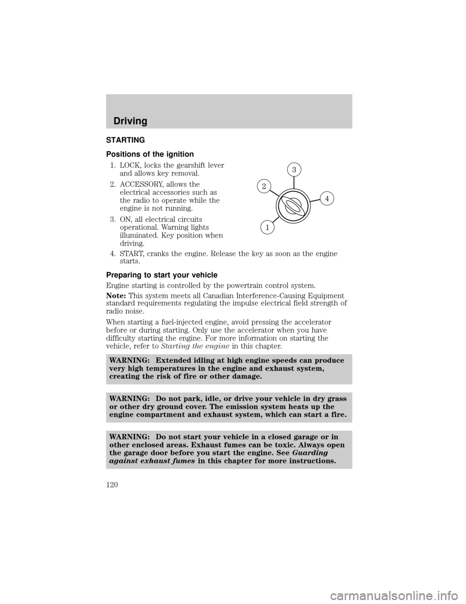
STARTING
Positions of the ignition
1. LOCK, locks the gearshift lever
and allows key removal.
2. ACCESSORY, allows the
electrical accessories such as
the radio to operate while the
engine is not running.
3. ON, all electrical circuits
operational. Warning lights
illuminated. Key position when
driving.
4. START, cranks the engine. Release the key as soon as the engine
starts.
Preparing to start your vehicle
Engine starting is controlled by the powertrain control system.
Note:This system meets all Canadian Interference-Causing Equipment
standard requirements regulating the impulse electrical field strength of
radio noise.
When starting a fuel-injected engine, avoid pressing the accelerator
before or during starting. Only use the accelerator when you have
difficulty starting the engine. For more information on starting the
vehicle, refer toStarting the enginein this chapter.
WARNING: Extended idling at high engine speeds can produce
very high temperatures in the engine and exhaust system,
creating the risk of fire or other damage.
WARNING: Do not park, idle, or drive your vehicle in dry grass
or other dry ground cover. The emission system heats up the
engine compartment and exhaust system, which can start a fire.
WARNING: Do not start your vehicle in a closed garage or in
other enclosed areas. Exhaust fumes can be toxic. Always open
the garage door before you start the engine. SeeGuarding
against exhaust fumesin this chapter for more instructions.
Driving
120
Page 155 of 248

HAZARD FLASHER CONTROL
The hazard flasher is located on the
instrument panel by the radio. The
hazard flashers will operate when
the ignition is off.
Push in the flasher control and all front and rear direction signals will
flash. Press the flasher control again to turn them off. Use it when your
vehicle is disabled and is creating a safety hazard for other motorists.
Note:With extended use, the flasher may run down your battery.
FUEL PUMP SHUT-OFF SWITCH
FUEL
RESET
This device stops the electric fuel pump from sending fuel to the engine
when your vehicle has had a substantial jolt.
After an accident, if the engine cranks but does not start, this switch
may have been activated.
This switch is located in the front
passenger's footwell, by the kick
panel access cover.
To reset the switch:
1. Turn the ignition OFF.
2. Check the fuel system for leaks.
3. Remove the kick panel access
cover, located in the front
passenger's footwell.
4. If no leaks are apparent, reset
the switch by pushing in on the
reset button.
5. Turn the ignition ON.
6. Wait a few seconds and return
the key to OFF.
7. Make another check of leaks.
Roadside Emergencies
155
Page 158 of 248
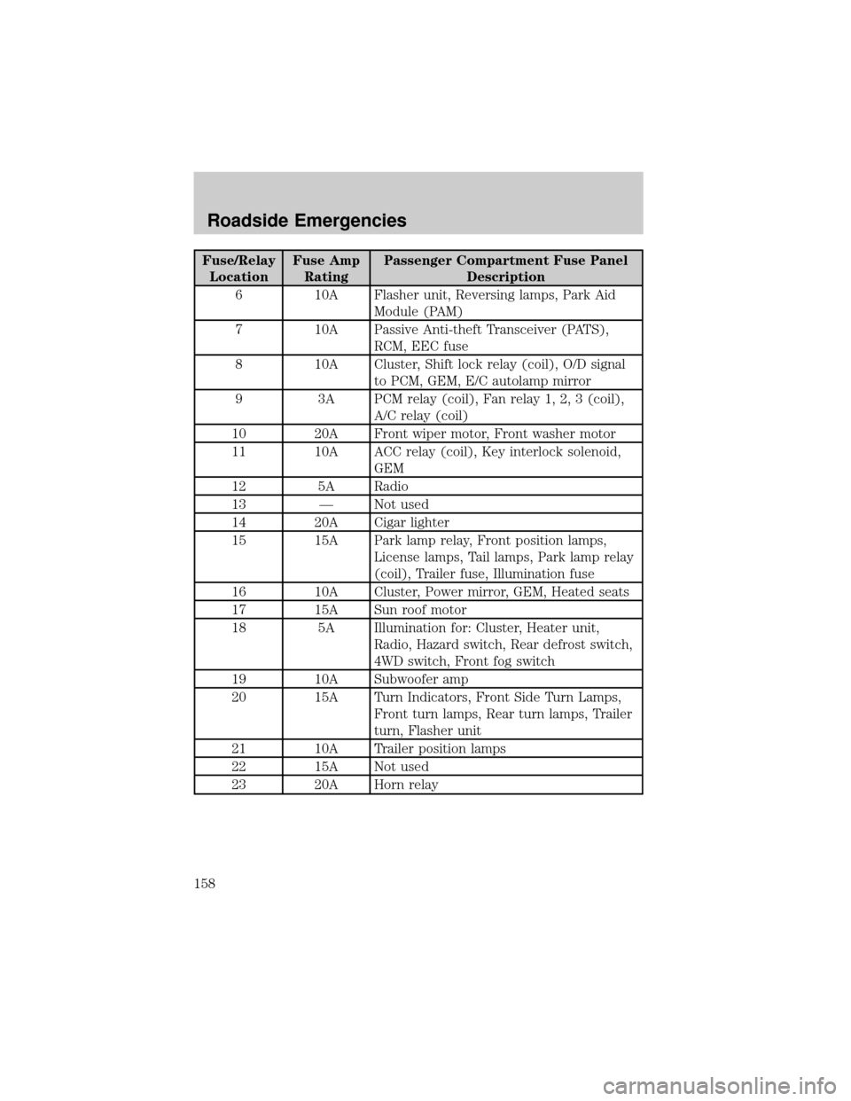
Fuse/Relay
LocationFuse Amp
RatingPassenger Compartment Fuse Panel
Description
6 10A Flasher unit, Reversing lamps, Park Aid
Module (PAM)
7 10A Passive Anti-theft Transceiver (PATS),
RCM, EEC fuse
8 10A Cluster, Shift lock relay (coil), O/D signal
to PCM, GEM, E/C autolamp mirror
9 3A PCM relay (coil), Fan relay 1, 2, 3 (coil),
A/C relay (coil)
10 20A Front wiper motor, Front washer motor
11 10A ACC relay (coil), Key interlock solenoid,
GEM
12 5A Radio
13 Ð Not used
14 20A Cigar lighter
15 15A Park lamp relay, Front position lamps,
License lamps, Tail lamps, Park lamp relay
(coil), Trailer fuse, Illumination fuse
16 10A Cluster, Power mirror, GEM, Heated seats
17 15A Sun roof motor
18 5A Illumination for: Cluster, Heater unit,
Radio, Hazard switch, Rear defrost switch,
4WD switch, Front fog switch
19 10A Subwoofer amp
20 15A Turn Indicators, Front Side Turn Lamps,
Front turn lamps, Rear turn lamps, Trailer
turn, Flasher unit
21 10A Trailer position lamps
22 15A Not used
23 20A Horn relay
Roadside Emergencies
158
Page 161 of 248
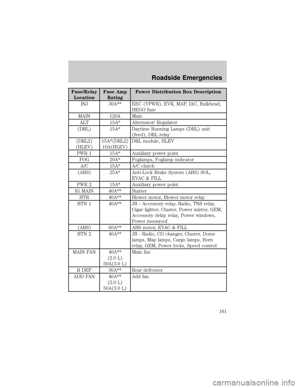
Fuse/Relay
LocationFuse Amp
RatingPower Distribution Box Description
INJ 30A** EEC (VPWR), EVR, MAF, IAC, Bulkhead,
HEGO fuse
MAIN 120A Main
ALT 15A* Alternator/ Regulator
(DRL) 15A* Daytime Running Lamps (DRL) unit
(feed), DRL relay
(DRL2)
(HLEV)15A*(DRL2)
10A(HLEV)DRL module, HLEV
PWR 1 15A* Auxiliary power point
FOG 20A* Foglamps, Foglamp indicator
A/C 15A* A/C clutch
(ABS) 25A* Anti-Lock Brake System (ABS) SOL,
EVAC & FILL
PWR 2 15A* Auxiliary power point
IG MAIN 40A** Starter
HTR 40A** Blower motor, Blower motor relay
BTN 1 40A** JB - Accessory relay, Radio, TNS relay,
Cigar lighter, Cluster, Power mirror, GEM,
Accessory delay relay, Power windows,
Power moonroof
(ABS) 60A** ABS motor, EVAC & FILL
BTN 2 40A** JB - Radio, CD changer, Cluster, Dome
lamps, Map lamps, Cargo lamps, Horn
relay, GEM, Power locks, Speed control
MAIN FAN 40A**
(2.0 L)
50A(3.0 L)Main fan
R DEF 30A** Rear defroster
ADD FAN 40A**
(2.0 L)
50A(3.0 L)Add fan
Roadside Emergencies
161
Page 182 of 248

AMERICAN SAMOA
Polynesia Motors, Inc.
P.O. Box 1120, Pago Pago, American Samoa 96799
TEL: (684) 699±1854
ADD-ON NON-GENUINE PARTS AND ACCESSORIES
Non-genuine parts and accessories for Mazda vehicles can be found in
stores. These may fit your vehicle, but they are not approved by the
manufacturer for use with Mazda vehicles. When you install non-genuine
parts or accessories, they could affect your vehicle's performance or
safety system; the manufacturer's warranty doesn't cover this. Before you
install any non-genuine parts or accessories, consult an Authorized
Mazda Dealer.
WARNING: Installation of Non-Genuine Parts or Accessories:
Installation of non-genuine parts or accessories could be
dangerous. Improperly designed parts or accessories could
seriously affect your vehicle's performance or safety system.
This could cause you to have an accident or increase your
chances of injuries in an accident. Always consult an Authorized
Mazda Dealer before you install non-genuine parts or
accessories.
WARNING: Add-On Electrical and Electronic Equipment:
Incorrectly choosing or installing improper add-on equipment or
choosing an improper installer could be dangerous. Essential
systems could be damaged, causing engine stalling, air-bag
(SRS) activation, ABS inactivation, or a fire in the vehicle. Be
very careful in choosing and installing add-on electrical
equipments, such as mobile telephones, two-way radios, stereo
systems, and car alarm systems.
Mazda assumes no responsibility for death, injury, or expenses that may
result from the installation of add-on non-genuine parts or accessories.
WARRANTIES FOR YOUR MAZDA
²New Vehicle Limited Warranty
²Safety Restraint System Limited Warranty
²Anti-perforation Limited Warranty
²Federal Emission Control Warranty
± Emission Defect Warranty
± Emission Performance Warranty
Customer Assistance
182
Page 209 of 248

transmission may shift firmly. This operation is considered normal and
will not affect function or durability of the transmission. Over time the
adaptive learning process will fully update transmission operation to its
optimum shift feel.
If the battery has been disconnected or a new battery has been installed,
the clock and the preset radio stations must be reset once the battery is
reconnected.
²Always dispose of automotive
batteries in a responsible manner.
Follow your local authorized
standards for disposal. Call your
local authorized recycling center
to find out more about recycling
automotive batteries.
ENGINE COOLANT
Checking engine coolant
The concentration and level of engine coolant should be checked at the
mileage intervals listed in the service maintenance section. The coolant
concentration should be maintained at 50/50 coolant and water, which
equates to a freeze point of -36É C (-34É F). Coolant concentration
testing is possible with a hydrometer or antifreeze tester (such as the
Rotunda Battery and Antifreeze Tester, 014±R1060). The level of coolant
should be maintained at the ªcold fullº of ªcold fill rangeº level in the
coolant reservoir. If the level falls below, add coolant per the instructions
in theAdding Engine Coolantsection.
Your vehicle was factory-filled with a 50/50 engine coolant and water
concentration. If the concentration of coolant falls below 40% or above
60%, the engine parts could become damaged or not work properly.A
50±50 mixture of coolant and water provides the following:
²freeze protection down to -36É C (-34É F).
²boiling protection up to 129É C (265É F).
²protection against rust and other forms of corrosion.
²an accurate temperature readout from the engine coolant
gauge.
LEAD
RETURN
RECYCLE
Maintenance and Specifications
209
Page 239 of 248

CELL PHONES
Use of cell phones and other devices by driver:
WARNING: Use of any electrical devices such as cell phones,
computers, portable radios, vehicle navigation or other devices
by the driver while the vehicle is moving is dangerous. Dialing a
number on a cell phone while driving also ties-up the driver's
hands. Use of these devices will cause the driver to be
distracted and could lead to a serious accident. If a passenger is
unable to use the device, pull off the right-of-way to a safe area
before use. If use of a cell phone is necessary despite this
warning, use a hands-free system to at least allow the hands
free to drive the vehicle. Never use a cell phone or other
electrical device while the vehicle is moving and, instead,
concentrate on the full-time job of driving.
Accessories
239