wiring MAZDA MX-5 1994 Workshop Manual
[x] Cancel search | Manufacturer: MAZDA, Model Year: 1994, Model line: MX-5, Model: MAZDA MX-5 1994Pages: 1708, PDF Size: 82.34 MB
Page 3 of 1708

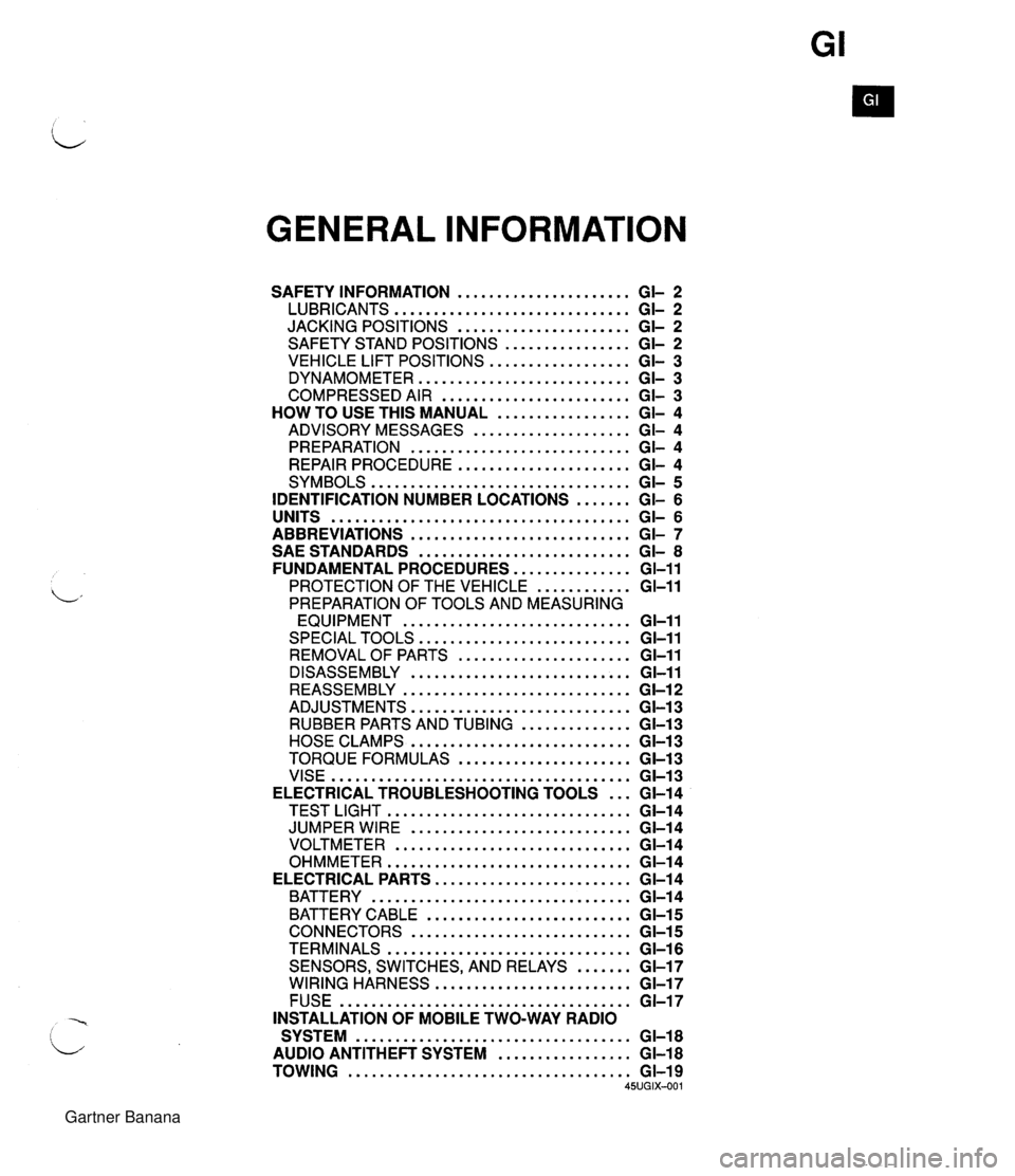
GENERAL INFORMATION SAFETY INFORMATION ...................... GI- 2 LUBRICANTS .............................. GI- 2 JACKING POSITIONS ...................... GI- 2 SAFETY STAND POSITIONS ................ GI- 2 VEHICLE LIFT POSITIONS .................. GI- 3 DYNAMOMETER ........................... GI- 3 COMPRESSED AIR ........................ GI- 3 HOW TO USE THIS MANUAL ................. GI- 4 ADVISORY MESSAGES .................... GI- 4 PREPARATION ............................ GI- 4 REPAIR PROCEDURE ...................... GI- 4 SYMBOLS ................................. GI- 5 IDENTIFICATION NUMBER LOCATIONS ....... GI- 6 UNITS ...................................... GI- 6 ABBREVIATIONS ............................ GI- 7 SAE STANDARDS ........................... GI- 8 FUNDAMENTAL PROCEDURES ............... GI-11 PROTECTION OF THE VEHICLE ............ GI-11 PREPARATION OF TOOLS AND MEASURING EQUIPMENT ............................. GI-11 SPECIAL TOOLS ........................... GI-11 REMOVALOF PARTS ...................... GI-11 DISASSEMBLY ............................ GI-11 REASSEMBLY ............................. GI-1 2 ADJUSTMENTS ............................ GI-13 RUBBER PARTS AND TUBING .............. GI-13 HOSE CLAMPS ............................ GC13 TORQUE FORMULAS ...................... GI-13 VISE ...................................... GI-13 ELECTRICAL TROUBLESHOOTING TOOLS ... GI-14 TEST LIGHT ............................... GI-14 JUMPER WIRE ............................ GC14 VOLTMETER .............................. GI-14 OHMMETER ............................... GI-14 ELECTRICAL PARTS ......................... GI-1 4 BATTERY ................................. GI-1 4 BATTERY CABLE .......................... GI-1 5 CONNECTORS ............................ GI-15 TERMINALS ............................... GI-16 SENSORS. SWITCHES. AND RELAYS ....... GI-17 WIRING HARNESS ......................... GI-17 FUSE ..................................... GI-17 INSTALLATION OF MOBILE TWO-WAY RADIO SYSTEM ................................... GI-18 AUDIO ANTITHEFT SYSTEM ................. GI-18 TOWING .................................... GI-19 45UGIX-001 Gartner Banana
Page 18 of 1708

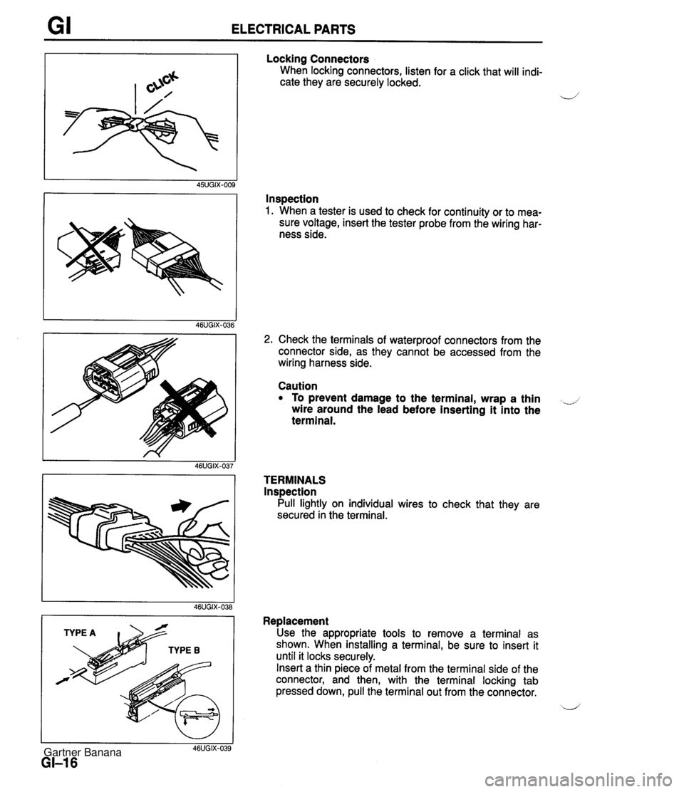
GI ELECTRICAL PARTS Locking Connectors When locking connectors, listen for a click that will indi- cate they are securely locked. 4' Inspection 1. When a tester is used to check for continuity or to mea- sure voltage, insert the tester probe from the wiring har- ness side. I I 46UGIX-039 GI-I 6 2. Check the terminals of waterproof connectors from the connector side, as they cannot be accessed from the wiring harness side. Caution To prevent damage to the terminal, wrap a thin ..J wire around the lead before inserting it into the terminal. TERMINALS lnspection Pull lightly on individual wires to check that they are secured in the terminal. Replacement Use the appropriate tools to remove a terminal as shown. When installing a terminal, be sure to insert it until it locks securely. Insert a thin piece of metal from the terminal side of the connector, and then, with the terminal locking tab pressed down, pull the terminal out from the connector. b' Gartner Banana
Page 19 of 1708

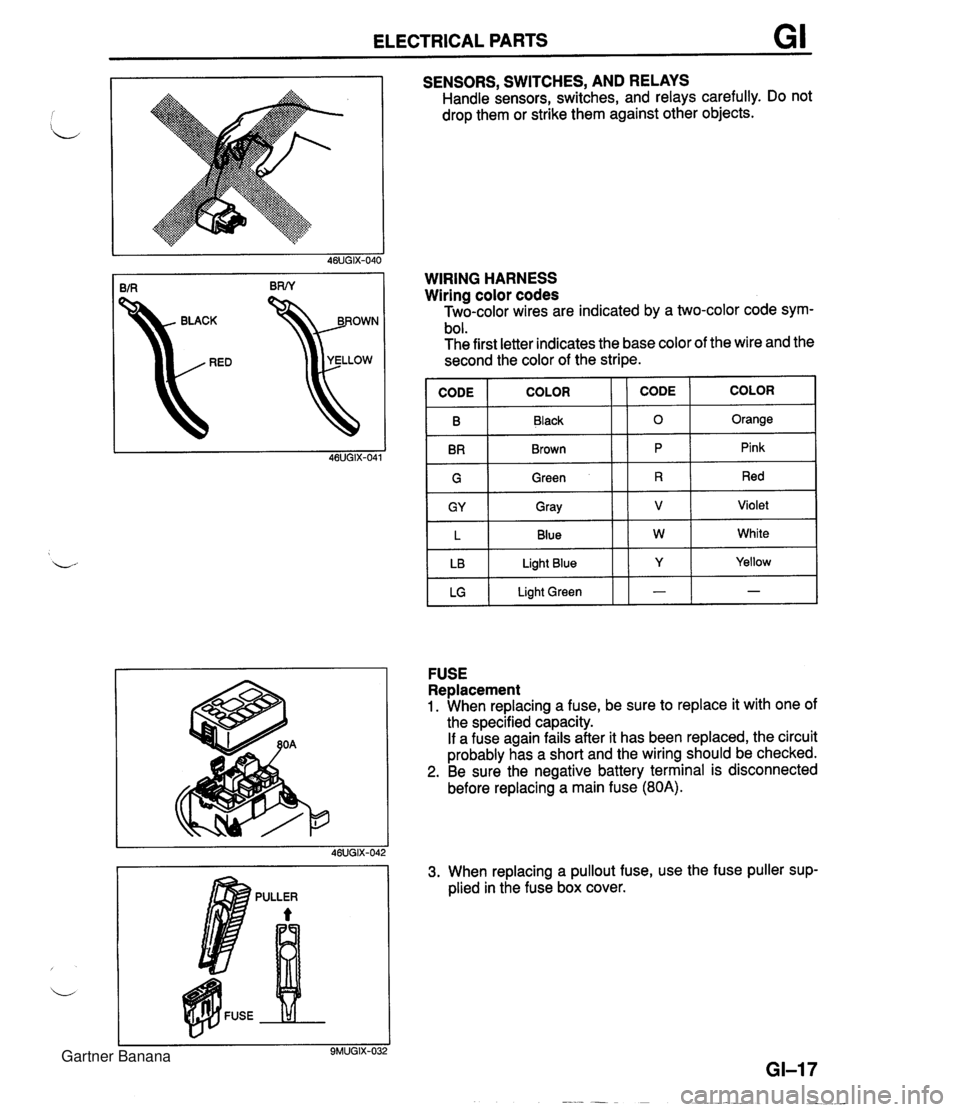
ELECTRICAL PARTS GI SENSORS, SWITCHES, AND RELAYS Handle sensors, switches, and relays carefully. Do not drop them or strike them against other objects. kD YELLOW WIRING HARNESS Wiring color codes Two-color wires are indicated by a two-color code sym- bol. The first letter indicates the base color of the wire and the second the color of the stripe. IGI Green 11 R 1 Red I B BR COLOR FUSE Replacement 1. When replacing a fuse, be sure to replace it with one of the specified capacity. If a fuse again fails after it has been replaced, the circuit probably has a short and the wiring should be checked. 2. Be sure the negative battery terminal is disconnected before replacing a main fuse (80A). CODE CODE Black Brown GY L LB LG 3. When replacing a pullout fuse, use the fuse puller sup- plied in the fuse box cover. COLOR 0 P Gray Blue Light Blue Light Green Orange Pink V W Y - Violet White Yellow - Gartner Banana
Page 150 of 1708

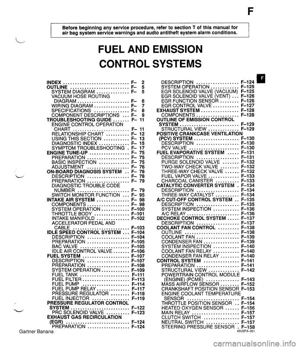
Before beginning any service procedure. refer to section T of this manual for air bag system service warnings and audio antitheft system alarm conditions . FUEL AND EMISSION CONTROL SYSTEMS INDEX ............................ F- 2 ......................... OUTLINE F- 5 .............. SYSTEM DIAGRAM F- 5 VACUUM HOSE ROUTING DIAGRAM ...................... F- 6 WIRING DIAGRAM ............... F- 7 SPECIFICATIONS ............... F- 8 COMPONENT DESCRIPTIONS ... F- 9 ....... TROUBLESHOOTING GUIDE F- 11 ENGINE CONTROL OPERATION CHART ........................ F- 11 RELATIONSHIP CHART .......... F- 12 USING THIS SECTION ........... F- 13 DIAGNOSTIC INDEX ............. F- 15 SYMPTOM TROUBLESHOOTING . F- 17 PREPARATION ................... F- 75 ............. BASIC INSPECTION F- 75 .................. ADJUSTMENT F- 76 ON-BOARD DIAGNOSIS SYSTEM . . F- 78 DESCRIPTION .................. F- 78 PREPARATION .................. F- 79 DIAGNOSTIC TROUBLE CODE NUMBER ...................... F- 79 ... SWITCH MONITOR FUNCTION F- 95 INTAKE AIR SYSTEM .............. F- 98 COMPONENTS .................. F- 98 SYSTEM OPERATION ............ F-100 THROTTLE BODY ............... F-101 INTAKE MANIFOLD .............. F-102 ACCELERATOR PEDAL AND CABLE ........................ F-103 IDLE SPEED CONTROL SYSTEM ... F-104 DESCRI PTlON .................. F-104 PREPARATION .................. F-105 BAC VALVE ..................... F-105 IDLE AIR CONTROL VALVE ....... F-106 FUEL SYSTEM .................... F-107 DESCRIPTION .................. F-107 PREPARATION .................. F-108 SYSTEM OPERATION ............ F-109 FUEL TANK ..................... F-111 FUEL FILTER .................... F-113 FUEL PUMP .................... F-114 FUEL PUMP RELAY .............. F-117 PRESSURE REGULATOR ........ F-118 FUEL INJECTOR ................ F-119 PRESSURE REGULATOR CONTROL SYSTEM ......................... F-122 PRC SOLENOID VALVE .......... F-123 EXHAUST GAS RECIRCULATION (EGR) ........................... F-124 PREPARATION .................. F-124 .................. DESCRIPTION F-124 SYSTEM OPERATION F-125 ............ EGR SOLENOID VALVE (VACUUM) F-125 EGR SOLENOID VALVE (VENT) ... F-126 ......... EGR FUNCTION SENSOR F-126 ........... EGR CONTROL VALVE F-127 ................ EXHAUST SYSTEM F-128 .................. COMPONENTS F-128 OUTLINE OF EMISSION CONTROL ......................... SYSTEM F-129 ............. STRUCTURAL VIEW F-129 POSITIVE CRANKCASE VENTILATION ................... (PCV) SYSTEM F-130 ' DESCRIPTION .................. F-I ..................... PCV VALVE F-1 ..... FUEL EVAPORATIVE SYSTEM F- .................. DESCRIPTION F- ....... PURGE SOLENOID VALVE F- ........ TWO-WAY CHECK VALVE F- ...... THREE-WAY CHECK VALVE F- ............. FUEL VAPOR VALVE F- .......... CHARCOAL CANISTER F- CATALYTIC CONVERTER SYSTEM . F- .................. DESCRIPTION F- .......... THREE-WAY CATALYST F- AIC CUT-OFF CONTROL SYSTEM . . F- .................. DESCRIPTION F- ........... SYSTEM INSPECTION F- ...................... A/c RELAY F-1 36 ..... DECHOKE CONTROL SYSTEM F-137 .................. DESCRIPTION F-137 ......... COOLANT FAN CONTROL F-138 ....................... OUTLINE F-138 .................. COOLANT FAN F-139 ............... CONDENSER FAN F-139 ........... SYSTEM INSPECTION F-140 ........... COOLANT FAN RELAY F-140 ........ CONDENSER FAN RELAY F-140 ............... CONTROL SYSTEM F-141 .................. PREPARATION F-141 ............. STRUCTURAL VIEW F-142 POWERTRAIN CONTROL MODULE .............. (ENGINE) (PCME) F-143 ........ MASS AIRFLOW SENSOR F-152 CRANKSHAFT POSITION SENSOR F-153 ENGINE COOLANT TEMPERATURE ...................... SENSOR F-154 THROTTLE POSITION SENSOR . . F-154 HEATED OXYGEN SENSOR ...... F-156 MAIN RELAY .................... F-157 ............... CLUTCH SWITCH F-157 NEUTRAL SWITCH .............. F-157 STEERING PRESSURE SENSOR . F-158 45UOFX-001 Gartner Banana
Page 156 of 1708

OUTLINE WIRING DIAGRAM Gartner Banana
Page 163 of 1708

F TROUBLESHOOTING GUIDE Troubleshooting chart F TROUBLESHOOTING GUIDE 7 I - page F-79 CRANKS NORMALLY BUT HARD TO START - AFTER WARM-UP 1 Check if PCME terminal voltaoes are OK Check If '00" is displayed on Sell-Diagnosis Check- er wilh lonillon switch ON I (2D* 2R and *) page 6145 'SCRIPTION Enginecranks at normal speed but requires excessive cranking time (more than 5 sec.) before starting after run- ning and hot soaked Battery In normal condition Engine starts normally when cold TROUBLESHOOTING HINTS] D AidFuel mixture too rich @ Vapor lock Fuel injection control malfunction . Fuel pressure not held In fuel line after engine stop Fuel injector fuel leakage . High RVP (winter) fuel used In warm weather ITEP I INSPECTlON Yes "88" flashes I Check PCME terminal I E ~Itg " p8gO F-I45 1 ACVON Go to next slep No Speclflcatlon: Baltery porltlve voltage (Ignition rwltch 1 ON) Diagnostic Trouble Code No. dlrplayed Check lor cause (Refer lo specified check sequence) a page F-81 If OK, replace PCME rr F-143 I:, if not OK, check wiring between PCME and Sell-Diagno- sis Checker LQ page M I No Check for cause (Refer to 'Check Pdnt for Each Terml- nal') page F-1 I -- ~ Yes Go lo next step I p- / Yes DESCRIPTION: Further describes the symptom. Confirm that the chart addresses the actual symptom before beginning troubleshooting. Go to next slep TROUBLESHOOTING HINTS: This describes the possible point of malfunction. STEP: This shows the order of troubleshooting. Proceed with troubleshooting as indicated. INSPECTION: This describes an inspection to quickly determine the malfunction of parts. If a detailed procedure is nec- essary to perform the INSPECTION, refer to the page shown by the "UW' mark. ACTION: This recommends the appropriate action to take as a result (YesINo) of the INSPECTION. How to per- form the action is described on the reference page shown by the "=" mark. Gartner Banana
Page 166 of 1708

TROUBLESHOOTING GUIDE SYMPTOM TROUBLESHOOTING 2 CRANKS NORMALLY BUT WILL NOT START (NO COMBUSTION) Engine cranks at normal speed but shows no sign of "firing" ESCwPTION : Battery in normal condition Throttle valve not held wide open throttle while cranking Fuel in tank rROUBLESHOOTlNG HINTS] ecause of no combustion, possibly no fuel is injected to engine or no ignition at all cylinders 1 No spark O Low fuel line pressure lanition control malfunction @ Low engine compression ignition system component malfunction I No fuel injection Fuel pump does not operate Fuel injector does not operate INSPECTION ACTION :heck if strong blue spark is visible at disconnected iigh-tension lead while cranking engine :heck if "00" is displayed on Self Diagnosis Checker ~ith ignition switch ON page F-79 Sonnect data link connector terminals F/P and GND ~ith jumper wire and check for fuel pump operating sound with ignition switch ON page F-114 Yes - No - Yes No - Yes - No Go to Step 3 Go to Step 2 Check ignition system (Refer to Troubleshooting "Misfire") mf Section G Diagnostic Trouble Code No. displayed Check for cause (Refer to specified check sequence) page F-81 "88" flashes Check PCME terminal 1 E voltage ojg. page F-145 Specification: Battery positive voltage (Ignition switch ON) 0 If OK, replace PCME us? page F-143 Q If not OK, check wiring between PCME and Self-Diagno- sis Checker page F-7 Check if engine starts in this condition 0 If starts, check fuel pump relay f@ page F-117 r3 If does not start, go to Step 5 Go to Step 4 Gartner Banana
Page 167 of 1708

F TROUBLESHOOTING GUIDE INSPECTION Check if battery positive voltage exists at fuel pump connector fuel pump positive terminal with jumper wire connected.(~tep 3 Check for fuel injector operating sound while crank- ing engine Check if battery positive voltage exists at fuel injector connector B terminal wire with ignition switch ON Connect data link connector terminals F/P and GND with jumper wire and check for correct fuel line pres- sure with ignition switch ON page F-110 Fuel Line pressure: 265--314 kPa f2.7-3.2 kgf/crn2, 38-46 psi) Check for correct engine compression Section B Engine compression: 1,255--883 kPa {12.&9.0 kgf/crn2, 182-1 28 psi)-300 rpm Check if spark plugs are OK WEAR AND CARBON BUILDUP BURNS PLUG GAP 1.0-l.lmm DAMAGE AND (0.040-0.043 in) DETERIORATION DAMAGE Try known good PCME and check if condition im- proves page F-144 - Yes - No Yes Yes - No Yes Yes - No - Yes ACTION Check continuity of fuel pump page F-114 Check fuel pump relay page F-117 Go to Step 7 Go to Step 6 Check PCME terminals 2A, 2U, 2V, 2Y and 22 voltages @3F page F-147 Check for open circuit in wiring between main relay and fuel injector page F-7 Go to next step Low pressure Check fuel line pressure while pinching fuel return hose 0 If fuel line pressure quickly increases, check pressure regulator page F-118 0 If fuel line pressure gradually increases, check for clog- ging between fuel pump and pressure regulator If not clogged, check fuel pump maximum pressure page F-115 Go to next step Check engine condition @3F Section B w Worn piston, piston rings or cylinder wall Defective cylinder head gasket w Distorted cylinder head Improper valve seating w Valve sticking in guide Go to next step Repair, clean, or replace Section G Gartner Banana
Page 168 of 1708

TROUBLESHOOTING GUIDE 3 CRANKS NORMALLY BUT WILL NOT START (PARTIAL COMBUSTION) -WHEN ENGINE IS COLD Engine cranks at normal speed but shows partial combustion and will not continue to run IESCRIPTION Battery in normal condition Fuel in tank TROUBLESHOOTING HINTS] B AirIFue! mixture too rich Q Low engine compression Air cleaner element clogged D AirIFuel mixture too lean Fuel injection control malfunction (Correction for coolant temperature) Low fuel line pressure Air leakage of intake air system 1 INSPECTION ACTION :heck if "00" is displayed on Self-Diagnosis Checker ~ith ignition switch ON as page F-79 Sheck if strong blue spark is visible at each discon- iected high-tension lead while cranking engine Connect data link connector terminals F/P and GND with jumper wire and check for correct fuel line pres- sure with ignition switch ON E+T page F-110 Fuel Line pressure: 265--314 kPa I2.7-3.2 kgf/cm2, 38-46 psi) INSTALL CLAPS ' Yes Yes Yes - No - Go to next step Diagnostic Trouble Code No. displayed Check for cause (Refer to specified check sequence) page F-81 "88" flashes Check PCME terminal 1 E voltage @f page F-145 Specification: Battery positive voltage (Ignition switch ON) O If OK, replace PCME page F-143 L:, If not OK, check wiring between PCME and Self-Diagno- sis Checker page F-7 Go to next step Check ignition system (Refer to Troubleshooting "Misfire") Section G Go to next step Low pressure Check fuel line pressure while pinching fuel return hose If fuel line pressure quickly increases, check pressure regulator page F-118 o If fuel line pressure gradually increases, check for clog- ging between fuel pump and pressure regulator If not clogged, check fuel pump maximum pressure page F-115 High pressure Check if fuel return hose is clogged or restricted O If OK, replace pressure regulator page F-119 s If not OK, repair or replace Gartner Banana
Page 170 of 1708
![MAZDA MX-5 1994 Workshop Manual TROUBLESHOOTING GUIDE 7 CRANKS NORMALLY BUT WILL NOT START (PARTIAL COMBUSTION) -AFTER WARM-UP I ~ngine starts normally when cold TROUBLESHOOTING HINTS] D AirIFuel mixture too rich O Vapor lock Fuel p MAZDA MX-5 1994 Workshop Manual TROUBLESHOOTING GUIDE 7 CRANKS NORMALLY BUT WILL NOT START (PARTIAL COMBUSTION) -AFTER WARM-UP I ~ngine starts normally when cold TROUBLESHOOTING HINTS] D AirIFuel mixture too rich O Vapor lock Fuel p](/img/28/57072/w960_57072-169.png)
TROUBLESHOOTING GUIDE 7 CRANKS NORMALLY BUT WILL NOT START (PARTIAL COMBUSTION) -AFTER WARM-UP I ~ngine starts normally when cold TROUBLESHOOTING HINTS] D AirIFuel mixture too rich O Vapor lock Fuel pressure not held in fuel line after engine stops High RVP (winter) fuel used in warm weather 'ESCRIPTIoN Fuel injection control malfunction (Correction for coolant temperature) Fuel injector fuel leakage I INSPECTION Engine cranks at normal speed but shows partial combustion and will not continue to run after running and hol soaked Battery in normal condition :heck if "00" is displayed on Self-Diagnosis Checker with ignition switch ON @S page F-79 :heck if PCME terminal voltages are OK :2D and 20) page F-136 sonnect data link connector terminals F/P and GND ~ith jumper wire and check for correct fuel line pres- sure with ignition switch ON page F-110 Fuel Line pressure: 26-14 kPa {2.7-3.2 kgflcm2, 38-46 psi) GND F~P INSTALL CLAPS ' Yes No - Yes - No Yes ACTION Go to next step Diagnostic Trouble Code No. displayed Check for cause (Refer to specified check sequence) page F-81 "88" flashes Check PCME terminal 1 E voltage page F-145 Specification: Battery positive voltage (Ignition switch ON) 0 If OK, replace PCME page F-143 0 If not OK, check wiring between PCME and Self-Diagno- sis Checker page F-7 Go to next step Check for cause (Refer to "Check Point for Each Terminal") page F-148 Go to next step Low pressure Check fuel line pressure while pinching fuel return hose Q If fuel line pressure quickly increases, check pressure regulator page F-118 0 If fuel line pressure gradually increases, check fuel line and filter for clogging If not clogged, check fuel pump maximum pressure page F-115 - High pressure Check if fuel return hose is clogged or restricted a If OK, replace pressure regulator page F-119 6 If not OK, repair or replace Gartner Banana