brake sensor MAZDA MX-5 1994 Workshop Manual
[x] Cancel search | Manufacturer: MAZDA, Model Year: 1994, Model line: MX-5, Model: MAZDA MX-5 1994Pages: 1708, PDF Size: 82.34 MB
Page 9 of 1708

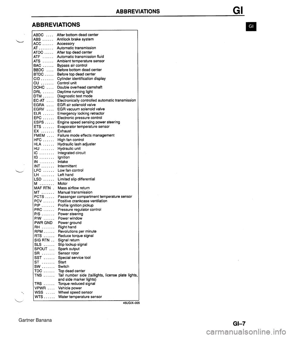
ABBREVIATIONS 4BDC .... 4BS ...... 4CC ...... 4T ........ 4TDC ..... 4TF ...... 4TS ...... 3AC ...... 3BDC .... 3TDC ..... :ID ....... 2U ....... IOHC .... IRL ...... ITM ...... IC-AT .... iGRA .... EGRV .... ELR ...... EPC ...... ESPS ..... ETS ...... EX ....... FMEM .... HFC ...... HLA ...... H U ....... IC ........ IG ........ IN ........ INT ....... LFC ...... LH ....... LSD ...... M ........ MAF RTN . MT ....... PCTS ..... PCV ...... PIP ....... PRC ...... PIS ....... PMI ...... PWR GND RH ....... RPM ...... RTS ...... SIG RTN . . SLS ...... ... SPOUT S R ....... SST ...... ST ....... SW ....... TDC ...... TNS ...... TRS ...... VPWR .... WSS ..... WTS...... After bottom dead center Antilock brake system Accessory Automatic transmission After top dead center Automatic transmission fluid Ambient temperature sensor Bypass air control Before bottom dead center Before top dead center Cylinder identification display Control unit Double overhead camshaft Daytime running light Diagnostic test mode Electronically controlled automatic transmission EGR air solenoid valve EGR vacuum solenoid valve Emergency locking retractor Electronic pressure control Engine speed sensing power steering Evaporator temperature sensor Exhaust Failure mode effects management High fan control Hydraulic lash adjuster Hydraulic unit Integrated circuit Ignition Intake Intermittent Low fan control Left hand Limited slip differential Motor Mass airflow return Manual transmission Passenger compartment temperature sensor Positive crankcase ventilation Profile ignition pickup Pressure regulator control Power steering Power window Power ground Right hand Revolutions per minute Reduce torque signal Signal return Slip lockup signal Spark output Sensor rotor Special service tool Start Switch Top dead center Tail number side (taillights, license plate lights and side marker lights) Torque reduced signal Vehicle power Wheel speed sensor Water temperature sensor Gartner Banana
Page 194 of 1708
![MAZDA MX-5 1994 Workshop Manual TROUBLESHOOTING GUIDE F 18 ENGINE STALLS DURING START-UP DESCRIPTKlN I Engine unexpectedly stops running while starting VROUBLESHOOTING HINTS] @ Misfire occurs when depressing accelerator Q Lack of en MAZDA MX-5 1994 Workshop Manual TROUBLESHOOTING GUIDE F 18 ENGINE STALLS DURING START-UP DESCRIPTKlN I Engine unexpectedly stops running while starting VROUBLESHOOTING HINTS] @ Misfire occurs when depressing accelerator Q Lack of en](/img/28/57072/w960_57072-193.png)
TROUBLESHOOTING GUIDE F 18 ENGINE STALLS DURING START-UP DESCRIPTKlN I Engine unexpectedly stops running while starting VROUBLESHOOTING HINTS] @ Misfire occurs when depressing accelerator Q Lack of engine torque for start-up AirIFuel mixture too rich or too lean AirIFuel mixture too rich or too lean Incorrect ignition timing Weak ignition INSPECTION Check if brakes are dragging Section P Check if "00 is displayed on Self-Diagnosis Check- er with ignition switch ON * page F-79 SELECT SW A Check switches for correct operation with Self- Diagnosis Checker Monitor Lamp and ignition switch ON @ page F-95 Disconnect heated oxygen sensor connector and :heck if condition improves SENSOR CONNECTOR -3 I I - Yes - No Yes Yes No - Yes Low intake air amount Low en~ine com~ression ACTION Repair us Section P Go to next step Go to next step -- Diagnostic Trouble Code No. displayed Check for cause (Refer to specified check sequence) page F-81 "88" flashes Check PCME terminal 1 E voltage us page F-145 Specification : Battery positive voltage (Ignition switch ON) If OK, replace PCME rc+r page F-143 6 If not OK, check wiring between PCME and Self-Diagno- sis Checker e page F-7 Go to next step Lamp not ONIOFF with specified switch Check for cause (Refer to specified check sequence) uw page F-96 Lamp always ON Check wiring between PCME terminal 1 D and Self-Diag- nosis Checker page F-7 Check heated oxygen sensor @s page F-156 Go to next step Gartner Banana
Page 246 of 1708

ON-BOARD DIAGNOSIS SYSTEM Stoplight switch OK Release brake pedal Stoplight switch (MT) Headlight switch PC: Stoplight switch malfunction (Refer to Section T) 0 Open circuit in wire harness from stoplight switch to powertrain control module (engine) Powertrain control module (engine) terminal 10 malfunction (Refer to page F-145) Headlight switch OK Turn OFF headlight switch I I NO ---c L, Blower switch YES Depress brake pedal and verify that monitor lamp illuminates PC: Headlight switch malfunction (Refer to section T) Open circuit in wire harness from headlight switch to powertrain control module (engine) Powertrain control module (engine) terminal 1 U malfunction (Refer to page F-146) Turn ON headlight switch Verify that monitor lamp illuminates Verify that monitor lamp illuminates NO - I YES YES Blower switch OK Turn OFF blower switch Air conditioning sensor PC: Blower switch malfunction (Refer to section T) 0 Open circuit in wire harness from blower switch to powertrain control module (engine) 0 Powertrain control module (engine) terminal IS malfunction (Refer to page F-146) 1 I YES I ' Set fan speed control to low position Turn air conditioning sensor ON, and verify that monitor lamp illuminates PC: Air conditioning sensor malfunction (Refer to Section U) Blower switch malfunction Open circuit in wire harness from air conditioning sensor to blower switch Powertrain control module (engine) terminal 1Q malfunction (Refer to page F-146) NO' 4 Air conditioning sensor OK Turn air conditioning sensor and blower switch OFF Rear window defroster switch Turn rear window defroster switch ON Is monitor lamp illuminated? NO PC: Rear window defroster switch malfunction (Refer to Section T) Open circuit in wire harness (Rear window defroster switch - PCME) PCME terminal 2L voltage incorrect (Refer to page F-146) PCME malfunction YES Turn rear window defroster switch OFF u Rear window defroster switch OK Gartner Banana
Page 294 of 1708

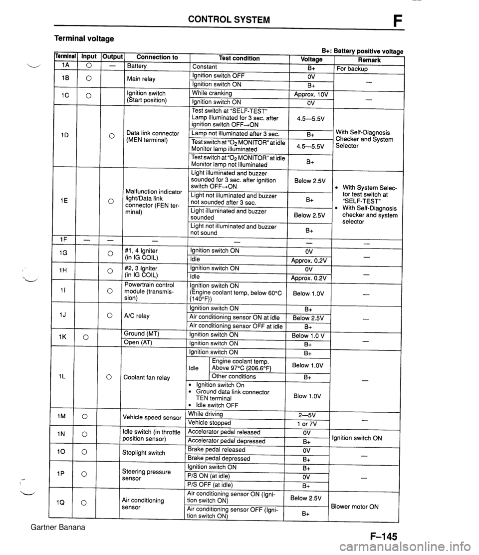
CONTROL SYSTEM F Terminal voltage B+: Battery positive voltage Test condition I Voltage I Remark - - - - - - - - - - - - - - - - - - Connection to Battery Constant Ignition switch OFF Main relay - B+ OV lgnition switch (Start position) For backup - Ignition switch ON While cranking Lamp illuminated for 3 sec. after 1 4.5-5.5V ianition switch OFF+ON 1 B+ Approx. 1 OV Ignition switch ON - - OV Data link connector (MEN terminal) Test switch at "SELF-TEST" .. Lamp not illuminated after 3 sec. Test switch at "02 MONITOR" at idle Monitor lam illuminated & 4.5-5.5v . . I Malfunction indicator IighVData link connector (FEN ter- minal) With Self-Diagnosis Checker and System Selector Test switch at "02 MONITOR" at idle Monitor lamp not illuminated Light illuminated and buzzer sounded for 3 sec. after ignition switch OFF-ON B+ tor tesiswitch at "SELF-TEST" With Self-Diagnosis checker and system selector Below 2.5V 1 Light illuminated and buzzer sounded 1 Below 2.5V I With System Selec- Light not illuminated and buzzer not sounded after 3 sec. I Light not illuminated and buzzer 1 n. 1 B+ not sound I D+ 1 - #I, 4 lgniter (in IG COIL) #2,3 Igniter (in IG COIL) Powertrain control module (transmis- sion) - Ignition switch ON Idle Ignition switch ON Idle lgnition switch ON (Engine coolant temp, below 60°C {I 40°F)) Ignition switch ON AtC relay Air conditioning sensor ON at idle Air conditioning sensor OFF at idle Ground (MT) - OV Approx. 0.2V OV Approx. 0.2V Below 1 .OV B+ Below 2.5V B+ - - - - , * Open (AT) - Ignition switch ON ( Below 1 .O V I Engine coolant temp. I Below .OV I ldle Above 97°C (206.6OF1 Ignition switch ON I I B+ Ignition switch ON Coolant fan relay B+ . - Other conditions lgnition switch On dround data link connector TEN terminal I Blow 1.0" I B+ Vehicle speed sensor ldle switch OFF While driving Vehicle sto~wed ldle switch (in throttle position sensor) 2-5V 1 or 7V . , Accelerator pedal released Accelerator ~edal de~ressed - Stoplight switch OV B+ Brake pedal released Brake ~edal deoressed lgnition switch ON Steering pressure sensor OV B+ I I - Ignition switch ON B+ - PIS ON (at idle) PIS OFF (at idle) Air conditioning sensor Air conditioning sensor ON (Igni- tion switch ON) Air conditioning sensor OFF (Igni- tion switch ON) OV B+ - Below 2.5V B+ Blower motor ON Gartner Banana
Page 402 of 1708

Before beginning any service procedure. refer to section T of this manual for air bag system service warnings and audio antitheft system alarm conditions . AUTOMATIC TRANSMISSION INDEX ................................ K- 2 OUTLINE ............................. K- 3 SPECIFICATIONS ................... K- 3 ........... CROSS-SECTIONAL VIEW K- 4 POWER FLOW DIAGRAM ............ K- 5 OPERATION OF COMPONENTS ...... K- 5 FLUID PASSAGE LOCATIONS ........ K- 6 TROUBLESHOOTING .................. K- 8 GENERAL NOTES ................... K- 8 .......... QUICK DIAGNOSIS CHART K- 9 ON-BOARD DIAGNOSIS SYSTEM ...... K- 11 DESCRIPTION ...................... K- 11 PREPARATION ...................... K- 11 ....... DIAGNOSTIC TROUBLE CODE K- 11 .......... MECHANICAL SYSTEM TEST K- 22 PREPARATION ...................... K- 22 STALL TEST ........................ K- 22 TIME LAG TEST ..................... K- 25 LINE PRESSURE TEST .............. K- 26 ROAD TEST .......................... K- 29 D-RANGE TEST ..................... K- 29 S-RANGE TEST ..................... K- 31 ..................... L-RANGE TEST K- 32 . P-RANGE TEST ..................... K- 33 AUTOMATIC TRANSMISSION FLUID (ATF) ................................ K- 35 ATF ................................ K- 35 REPLACEMENT ..................... K- 37 ELECTRICAL SYSTEM COMPONENTS . . K- 38 PREPARATION ...................... K- 38 HOLD SWITCH ...................... K- 38 PARWNEUTRAL SWITCH ............ K- 39 .............. ATF THERMOSENSOR K- 41 VEHICLE SPEED PULSE GENERATOR ...................... K- 41 1-2 SHIFT. 2-3 SHIFT. 3-4 SHIFT. ... 3-2 CONTROL SOLENOID VALVE K- 42 LOCKUP CONTROL SOLENOID ....... VALVE ............................ K- 42 POWERTRAIN CONTROL MODULE (TRANSMISSION) .................. K- 43 TRANSMISSION ....................... K- 46 TRANSMISSION UNIT (REMOVAL) .... K- 46 TRANSMISSION UNlT (DISASSEMBLY) ................... K- 50 TORQUE CONVERTER .............. K- 61 OILPUMP .......................... K- 62 FOURTH GEAR CONNECTING SHELL AND FOURTH GEAR PLANETARY GEAR UNIT (FOURTH GEAR SUN GEAR. FOURTH GEAR PLANETARY PINION CARRIER. FOURTH GEAR CLUTCH HUB) ...... K- 67 DIRECT CLUTCH .................... K- 70 FOURTH GEAR BAND SERVO ........ K- 76 DRUM SUPPORT. ACCUMULATOR. AND FOURTH GEAR CASE ......... K- 79 2ND BAND SERVO .................. K- 83 FRONT CLUTCH .................... K- 86 REAR CLUTCH ...................... K- 91 CONNECTING SHELL AND FRONT PLANETARY GEAR UNlT (REAR CLUTCH HUB. FRONT PLANETARY PINION CARRIER. REAR SUN GEAR) ................. K- 96 REAR PLANETARY GEAR UNlT (CONNECTING DRUM. REAR PLANETARY PINION CARRIER. ONE-WAY CLUTCH) K- 98 LOW AND REVERSE BRAKE K-102 ................ ......... EXTENSION HOUSING AND PARKING MECHANISM ............. K-107 OIL SEAL ........................... K-ill CONTROL VALVE BODY ............. K-112 UPPER VALVE BODY ................ K-116 LOWER VALVE BODY ............... K-120 CONTROL VALVE BODY ............. K-125 VACUUM DIAPHRAGM ............... K-130 TRANSMISSION UNIT (ASSEMBLY) ... K-132 TRANSMISSION UNIT (INSTALLATION) ................... K-147 OIL COOLER .......................... K-151 REMOVAL I INSPECTION I INSTALLATION ..................... K-151 DRIVE PLATE ......................... K-152 PREPARATION ...................... K-152 REMOVAL 1 INSPECTION I INSTALLATION ..................... K-152 SHIFT MECHANISM (WITH SHIFT-LOCK SYSTEM) ......... K-154 SHIFT-LOCK SYSTEM COMPONENTS K-154 TROUBLESHOOTING ................ K-155 SHIFT-LOCK ........................ K-157 EMERGENCY OVERRIDE BUTTON ... K-157 KEY INTERLOCK .................... K-157 KEY INTERLOCK SOLENOID ......... K-157 KEY INTERLOCK UNIT ............... K-158 P RANGE SWITCH .................. K-159 SHIFT-LOCKACTUATOR ............. K-159 SELECTOR LEVER .................. K-161 HYDRAULIC CIRCUIT .................. K-168 P RANGE ........................... K-168 R RANGE ........................... K-169 N RANGE; BELOW 7 kmlh I4.34 mph) . K-170 N RANGE; ABOVE 9 kmlh (5.58 mph} . K-171 D RANGE; 1 ST GEAR ................ K-172 D RANGE; 2ND GEAR ............... K-173 D RANGE; THIRD GEAR ............. K-174 D RANGE; FOURTH GEAR. LOCKUP ON ....................... K-175 S RANGE; 1 ST GEAR ................ K-176 S RANGE; 2ND GEAR ............... K-177 S RANGE; THIRD GEAR ............. K-178 L RANGE; 1 ST GEAR ................ K-179 L RANGE; 2ND GEAR ................ K-180 Gartner Banana
Page 404 of 1708

INDEX, OUTLINE K 1. Hold switch lnspection . . . . . . . . . . . . . . . . page K- 38 Replacement . . . . . . . . . . . . . page K- 39 b 2. ParkINeutral switch lnspection . . . . . . . . . . . . . . . . page K- 39 Adjustment . . . . . . . . . . . . . . . page K- 40 3. Vehicle speed pulse generator lnspection . . . . . . . . . . . . . . . . page K- 41 Replacement . . . . . . . . . . . . . page K- 42 4. ATF thermosensor lnspection . . . . . . . . . . . . . . . . page K- 41 Replacement . . . . . . . . . . . . . page K- 41 5. 1-2 shift, 2-3 shift, 3-4 shift, 3-2 control solenoid valves lnspection . . . . . . . . . . . . . . . . page K- 42 6. Lockup control solenoid valve lnspection . . . . . . . . . . . . . . . . page K- 42 7. Powertrain control module (Transmission) lnspection . . . . . . . . . . . . . . . . page K- 43 Replacement . . . . . . . . . . . . . page K- 45 OUTLINE SPECIFICATIONS 8. Automatic transmission Removal . . . . . . . . . . . . . . . . . page K- 46 Disassembly . . . . . . . . . . . . . page K- 50 Assembly . . . . . . . . . . . . . . . . page K-132 lnstallation . . . . . . . . . . . . . . . page K-147 9. Oil cooler Removal 1 Inspection / lnstallation . . . . . . . . . . . . . . page K-151 10. Drive plate Removal 1 Inspection 1 lnstallation . . . . . . . . . . . . . . page K-152 11. P range switch lnspection . . . . . . . . . . . . . . . . page K-159 12. Shift-lock actuator lnspection . . . . . . . . . . . . . . . . page K-159 13. Selector lever lnspection . . . . . . . . . . . . . . . . page K-161 Adjustment . . . . . . . . . . . . . . . page K-160 Removal / Inspection / lnstallation . . . . . . . . . . . . . . page K-163 Disassembly 1 Inspection / Assembly . . . . . . . . . . . . . . . page K-166 - Model Item - Gear ratio NC4A-EL Torque converter stall torque ratio 1 st 1.900 : 1 2.458 4GR Reverse 0.720 2.182 Number of driveldriven plates Servo diameter (Piston outer diameterketainer inner diam- eter) mm{in} Direct clutch Front clutch Rear clutch Automatic transmission fluid (Am 212 315 515 Low and reverse brake Fourth gear band servo 2nd band servo 4/4 56/36 {2.205/1.417} 72/50 {2.835/1.969} Dexron@II or M-111 7.3 {7.7,6.4} 4.0 {4.2,3.5} Type Capacity L {US qt, Imp qtI Total oil pan Gartner Banana
Page 414 of 1708

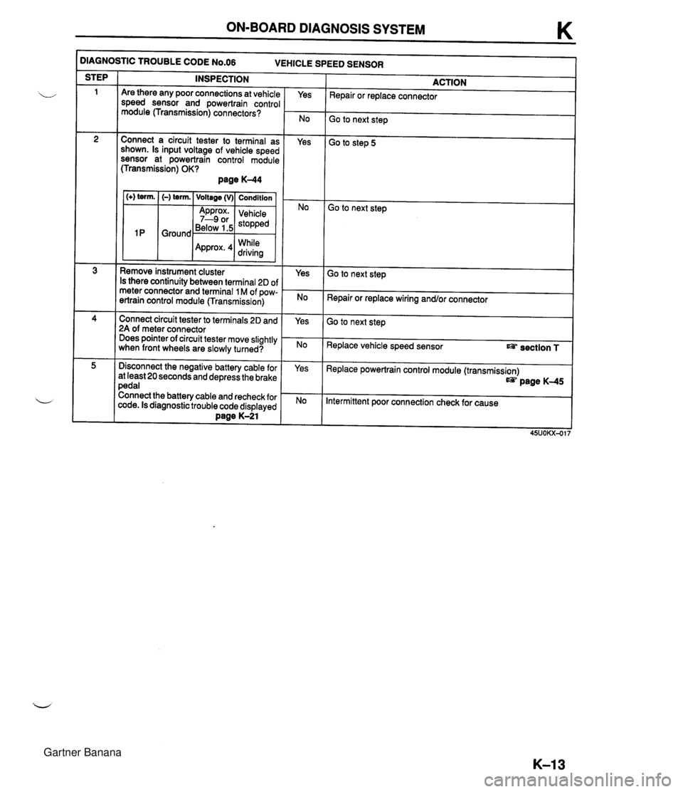
ON-BOARD DIAGNOSIS SYSTEM K )IAGNOSTIC TROUBLE CODE N0.06 VEHICLE SPEED SENSOR INSPECTION STEP ACTION Repair or replace connector Are there any poor connections at vehicle speed sensor and powertrain control module (Transmission) connectors? Yes Go to next step Connect a circuit tester to terminal as shown. Is input voltage of vehicle speed sensor at powertrain control module (Transmission) OK? page K-44 Yes Go to step 5 1 (+) term. I (-) term. ( Voltage (v)( Condition I Go to next step Below 1.5 While Remove instrument cluster Is there continuity between terminal 2D of meter connector and terminal 1 M of pow- ertrain control module (Transmission) Yes Go to next step Repair or replace wiring and/or connector Connect circuit tester to terminals 2D and 2A of meter connector Does pointer of circuit tester move slightly when front wheels are slowly turned? Yes Go to next step Replace vehicle speed sensor section T Disconnect the negative battery cable for at least 20 seconds and depress the brake pedal Connect the battery cable and recheck for code. Is diagnostic trouble code displayed Dane K-21 Yes Replace powertrain control module (transmission) page K-45 Intermittent poor connection check for cause Gartner Banana
Page 415 of 1708

K ON-BOARD DIAGNOSIS SYSTEM - -- )IAGNOSTIC TROUBLE CODE N0.12 THROTTLE POSITION SENSOR ACTION I STEP INSPECTION Are there any poor connections at throttle position sensor and powertrain control module (transmission) connector or termi- nal? Yes Repair or replace connector I Go to next step Go to step 5 Connect a circuit tester to terminal as shown Is input voltage of throttle position sensor (TVO) at powertrain control module (transmission) OK? page K-45 1 (+) term. I (-) term. I Voltage (v)/ Condition 1 Yes No lgnition Go to next step ' 2T Ground valve Approx. closed I 0.8--4.3 position to wide open 1 throttle Go to next step Connect a circuit tester to terminals as shown Is input voltage of throttle position sensor (VREF) at powertrain control module (transmission) OK? page K-44 (+) term. (-) term. Voltage (V) Condition Approx. lgnition 4.55 ;p" 2A Ground Ignition 0 switch OFF Yes Check voltage at terminal 21 of powertrain control module (En- gine) Voltage: 4.5--5.5V (Ignition switch ON) If OK, go to next step If not OK, repair wiring andlor connector Check wiring and connectors form Powertrain control module (transmission) to throttle position sensor If OK, go to next step If not OK, repair wiring andlor connector Is throttle position sensor OK? Section F Yes No Yes Adjust or replace throttle position sensor t@? section F I Replace powertrain control module (transmission) t@? page K-45 is connect the negative battery cable for at least 20 seconds and depress the brake pedal Connect the battery cable and recheck for diagnostic trouble code Is diagnostic trouble code displayed? Daae K-21 Intermittent poor connection Check for cause Gartner Banana
Page 432 of 1708

ROAD TEST K Evaluation I No lockup shift Condition No 1-2 up or downshift No 2-3 up or downshift No 3-4 up or downshift I Stuck lockup control solenoid valve Stuck locku~ control valve Possible Cause Stuck 1-2 shift solenoid valve Stuck 1-2 shift valve Stuck 2-3 shift solenoid valve Stuck 2-3 shift valve Stuck 3-4 shift solenoid valve Stuck 3-4 shift valve Incorrect shift point I No enaine brakina effect I Worn clutches, brakes I Misadjusted throttle position sensor Sticking shift valves Excessive shift shock or slippage Noise and Vibration Drive the vehicle in fourth gear (lockup), fourth gear (no lockup), and third gear (Hold) and listen closely for any out of the ordinary noise or vibration. The torque converter, propeller shaft, and differential can be sources of abnormal noise and vibration if they are not functioning properly. Check these when searching for sources of noise and vibration. Stuck accumulators Stuck or no one-way check orifice Stuck 3-2 control solenoid valve Stuck 3-2 control valve Worn clutches, brakes, or one-way clutch Kickdown Drive the vehicle in fourth gear, third gear, and 2nd gear and check that kickdown occurs for 4-+3,4-+2, 4+1,3+2,3+1, 2+1, and that the shift points are as shown in the shift diagram. ,U (Refer to pages K-29, 30.) S-RANGE TEST Shift Pattern For this test it is not necessary to inspect shift shock and shift points, since they are almost exactly the same as those for the D-range test. However, in the D-range (Normal) shift diagram, the shift points are different. In S range, the shift patterns for Normal mode are the same. 1. Shift the selector lever to S range and select the Normal mode. 2. Accelerate the vehicle and verify that 1-2 and 2-3 up-and downshifts are obtained, and that no fourth gear and no lockup (below approx. 100 kmlh (63 mph}) are obtained. 3. While driving in S range (Normal mode) and third gear, select the Hold mode and verify that third gear is held until ihe 3-2 downshift point as shown in the S range (Hold) shift diagram is achieved. 4. Accelerate the vehicle in S range (Hold mode) and verify that 2nd gear is held. S-range (Power) shift diagram LOCKUP AVAILABLE WHEN ACCELERATING AND CRUSING LOCKUP AVAILABLE WHEN COASTING -. - VEHICLE SPEED kmlh (rnph} Gartner Banana
Page 591 of 1708

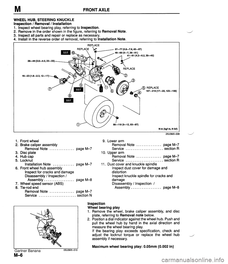
FRONT AXLE WHEEL HUB, STEERING KNUCKLE Inspection / Removal / lnstallation 1. lnspect wheel bearing play, referring to Inspection. 2. Remove in the order shown in the figure, referring to Removal Note. 3. lnspect all parts and repair or replace as necessary. 4. Install in the reverse order of removal, referring to Installation Note. 25UOMX-OC 1. Front wheel 9. Lower arm 2. Brake caliper assembly Removal Note .............. page M-7 3. Disc plate 4. Hub cap 5. Locknut Installation Note ............ page M-7 6. Front wheel hub assembly lnspect for cracks and damage Disassembly / Inspection / Assembly ................. page M-8 7. Wheel speed sensor (ABS) 8. Tie-rod end Removal Note .............. page M-7 Service ..................... section N .............. Removal Note page M-7 ..................... Service section R 10. Upper arm .............. Removal Note page M-7 ..................... Service section R 11. Dust cover and knuckle spindle lnspect dust cover for damage and distortion lnspect knuckle spindle for cracks and damage Disassembly / Inspection 1 ................. Assembly page M-8 lnspection Wheel bearing play 1. Remove the wheel, brake caliper assembly, and disc plate, referring to Removal note below. 2. Position a dial indicator against the wheel hub. Push and pull the wheel hub by hand in the axial direction and measure the wheel bearing play. If the bearing play exceeds specification, check and adjust the locknut torque or replace the wheel hub i assembly if necessary. Maximum wheel bearing play: 0.05mm i0.002 in) Gartner Banana