clutch MAZDA MX-5 1994 Workshop Manual
[x] Cancel search | Manufacturer: MAZDA, Model Year: 1994, Model line: MX-5, Model: MAZDA MX-5 1994Pages: 1708, PDF Size: 82.34 MB
Page 1069 of 1708

TROUBLESHOOTING u 7- Symptom: Magnetic clutch does not operate I Normal operation of magnetic clutch The PCME controls the operation of the condenser fan and magnetic clutch, depending on engine load. (Refer to section F.) The magnetic clutch is supplied with battery positive voltage as follows: 1. The ACS and fan switch are turned on. 2. The PCME receives a signal that the ACS and fan switch are on and creates a ground circuit. 3. The A/C relay is magnetized and the contact is closed. 4. Battery positive voltage is applied to the magnetic clutch and the clutch locks. WIPER 20A AD FAN 20A FUSE BLOCK MAIN FUSE BLOCK Step 1 1. Check the following fuses. I Fuse I Amperage I Location I I I . - I WIPER I 20A 1 In fuse block I I AD FAN I 20A 1 In main fuse block I 2. If the fuses are OK, go to Step 2. 3. If a fuse is burned, check for a short circuit in the harness before replacing it. Step 2 1. Run the engine at idle. 2. Turn on the ACS and fan switch. 3. Measure the voltage at the A terminal wire of the mag- netic clutch connector. B+: Battery positive voltage I Terminal I Voltage I Action 1 Step 3 1. Start the engine. 2. Turn on the fan switch and ACS. 3. Measure the voltage at terminal C and A of the A/C relay connector. B+: Batterv positive voltaae - -- A 1 Terminal I V0lta0e 1 Action I I C I Other I Repair wiring harness (AD FAN 20A fuse - AIC relay) I B+ Other I 1. -. B+ I GO to step 4 Replace magnetic clutch Go to Step 3 I A 1 Other I Repair wiring harness (WIPER 20A fuse - AIC relay) I Gartner Banana
Page 1070 of 1708

u TROUBLESHOOTING Step 4 1. Remove the relay. 2. Apply battery positive voltage and check for continuity between the relay terminals. B+: Battery positive voltage 0---0 : Continuity I I I 45U0UX-013 3. If correct, repair wiring harness (AC relay - magnetic clutch). 4. If not as specified, replace the A/C relay. 1 0 10 I I I 2 1 B+ 1 GND 1 0 I Gartner Banana
Page 1071 of 1708

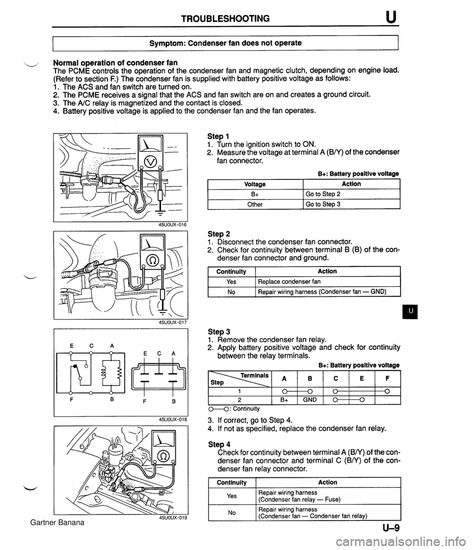
TROUBLESHOOTING u Symptom: Condenser fan does not operate Normal operation of condenser fan The PCME controls the operation of the condenser fan and magnetic clutch, depending on engine load. (Refer to section F.) The condenser fan is supplied with battery positive voltage as follows: 1. The ACS and fan switch are turned on. 2. The PCME receives a signal that the ACS and fan switch are on and creates a ground circuit. 3. The A/C relay is magnetized and the contact is closed. 4. Battery positive voltage is applied to the condenser fan and the fan operates. Step 1 1. Turn the ignition switch to ON. 2. Measure the voltage at terminal A (B/Y) of the condenser fan connector. B+: Battery positive voltage Step 2 1. Disconnect the condenser fan connector. 2. Check for continuity between terminal B (B) of the con- denser fan connector and ground. Voltage B+ Other I GO to step 3 Action Go to Step 2 I continuity I Action I Step 3 1. Remove the condenser fan relay. 2. Apply battery positive voltage and check for continuity between the relay terminals. B+: Battery positive voltage Yes No Replace condenser fan Repair wiring harness (Condenser fan - GND) M: Continuity - - - 3. If correct, go to Step 4. 4. If not as specified, replace the condenser fan relay. 1 0 2 B+ Step 4 Check for continuity between terminal A (BN) of the con- denser fan connector and terminal C (BN) of the con- denser fan relay connector. I Continuity I Action 1 Repair wiring harness (Condenser fan relay - Fuse) B 0 GND I Repair wiring harness (Condenser fan - Condenser fan relay) I C 0 0 E 0 F 0 Gartner Banana
Page 1076 of 1708

u TROUBLESHOOTING Case 6: Expansion valve stuck open Measured pressure Low-pressure side: 0.30-0.39 MPa {3.0-4.0 kgf/cm2, 43-56 psi) High-pressure side: 1.97-2.45 MPa (20.0-25.0 kgf/cm2, 285-355 psi) Condition Insufficient cooling. CAUSE ACTION 7 m EXPANSION REPLACE / VALWEiUCK I *I EXPANSION VALVE Case 7: Faulty AIC compressor Measured pressure 1. Check whether there is frost or heavy dew on the suction pipe (between cooling unit and AIC compressor). 2. If neither is found, refer to "Excessive refrigerant or insuf- ficient condenser cooling"; page U-12. 3. If either is found, replace the expansion valve. (Refer to page U-31.) LOW-pressure side: 0.4-0.5 MPa (4.0-6.0 kgf/cm2, 57-85 psi) High-pressure side: 0.69-0.98 MPa (7.0-10.0 kgflcm2, 100-1 42 psi) Condition No cooling. I 1 Remedy CAUSE ACTION MOISTURE IN 1. Run ihe engine at a first idle. 2. Verify that the magnetic clutch is on when the ACS and fan switch are on. 3. If the magnetic clutch remains off, refer to "Magnetic clutch does not operate"; page U-7. Gartner Banana
Page 1085 of 1708

AIR CONDITIONER U AIR CONDITIONER PREPARATION i, SST I I c STRUCTURAL VIEW 00007-10331 Stopper, magnetic clutch 4992-02-020 Pressure plate remover For removal and installation of magnetic clutch For removal of pressure plate 1. Cooling unit 5. Condenser fan relay Removal I Installation ......... page U-30 Inspection ................... page U-37 Disassembly I Assembly ...... page U-31 6. AX: compressor 2. Condenser Removal I Installation ......... page U-38 Removal I Installation ......... page U-33 Disassembly I Assembly ...... page U-41 w 3. Receiver drier 7. Magnetic clutch Removal / Installation ......... page U-33 Disassembly / Assembly ...... page U-39 4. A/C relay Inspection ................... page U-37 Gartner Banana
Page 1099 of 1708

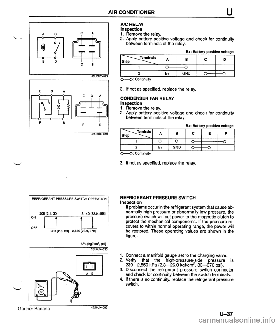
AIR CONDITIONER REFRIGERANT PRESSURE SWITCH OPERATION 206 {2.1,30) 3,140 (32.0, 455) OFF ON n 230 {2.3,33) 2,550 (26.0,370) A/C RELAY Inspection 1. Remove the relay. 2. Apply battery positive voltage and check for continuity between terminals of the relay. B+: Battery positive voltage 3. If not as specified, replace the relay. CONDENSER FAN RELAY lnspection 1. Remove the relay. 2. Apply battery positive voltage and check for continuity between terminals of the relay. B+: Battery positive voltage 1 2 O--(): Continuity 3. If not as specified, replace the relay. 0 B+ 1 2 REFRIGERANT PRESSURE SWITCH lnspection If problems occur in the refrigerant system that cause ab- normally high pressure or abnormally low pressure, the pressure switch will cut power to the magnetic clutch to protect the mechanical components. If the pressure re- covers to within normal operating range, the power will be restored. These operating values are shown in the figure. kPa (kgf/cm2, psi) 35UOUX-020 1. Connect a manifold gauge set to the charging valve. 2. Verify that the high-pressure-side pressure is 230-2,550 kPa (2.3-26.0 kgf/cm2, 33-370 psi). 3. Disconnect the refrigerant pressure switch connector and check for continuity between the switch terminals. 4. If there is no continuity, replace the refrigerant pressure switch. 45UOUX-085 0 GND 0 B+ 0 0 GND 0 0 0 0 3 Gartner Banana
Page 1100 of 1708

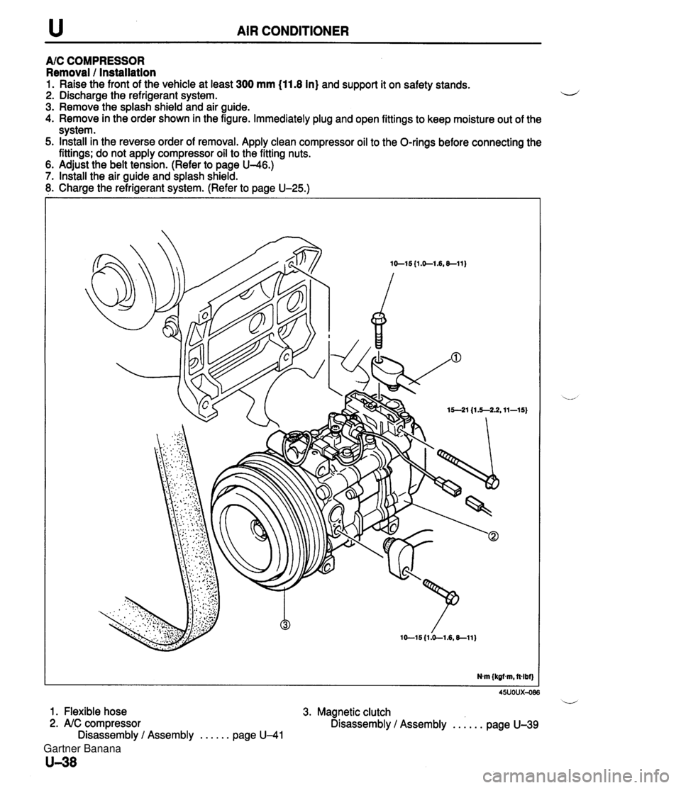
u AIR CONDITIONER A/C COMPRESSOR Removal / Installation 1. Raise the front of the vehicle at least 300 mm (11.8 In) and support it on safety stands. 2. Discharge the refrigerant system. i~ 3. Remove the splash shield and air guide. 4. Remove in the order shown in the figure. Immediately plug and open fittings to keep moisture out of the system. 5. Install in the reverse order of removal. Apply clean compressor oil to the O-rings before connecting the fittings; do not apply compressor oil to the fitting nuts. . 6. Adjust the belt tension. (Refer to page U-46.) 7. Install the air guide and splash shield. 8. Charge the refrigerant system. (Refer to page U-25.) 45uoux-086 i/ 1. Flexible hose 3. Magnetic clutch 2. AIC compressor Disassembly / Assembly . . . . . . page U-39 Disassembly / Assembly . . . . . . page U-41 Gartner Banana
Page 1101 of 1708

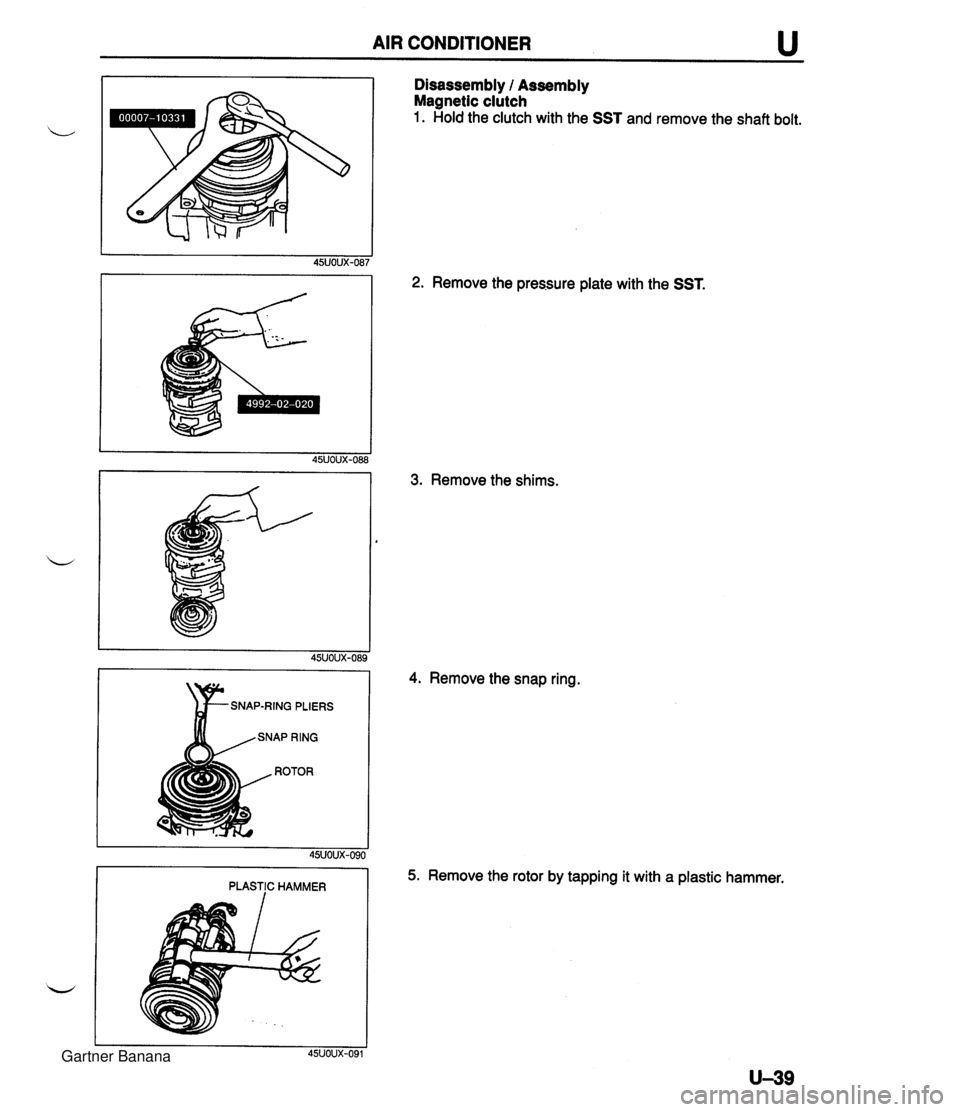
AIR CONDITIONER u Disassembly l Assembly Magnetic clutch 1. Hold the clutch with the SST and remove the shaft bolt. 2. Remove the pressure plate with the SST. 3. Remove the shims. SNAP-RING PLIERS PLASTIC HAMMER 4. Remove the snap ring. 5. Remove the rotor by tapping it with a plastic hammer. Gartner Banana
Page 1109 of 1708

TECHNICAL DATA MEASUREMENTS ......................... TD- 2 ................................... ENGINE TD- 2 .................... LUBRICATION SYSTEM TD- 5 ........................ COOLING SYSTEM TD- 5 FUEL AND EMISSION CONTROL SYSTEMS . TD- 6 ENGINE ELECTRICAL SYSTEM ............. TD- 7 .................................. CLUTCH TD- 7 .................. MANUAL TRANSMISSION TD- 8 AUTOMATIC TRANSMISSION ............... TD- 9 ....................... PROPELLER SHAFT TD-11 FRONT AND REAR AXLES ................. TD-12 STEERING SYSTEM ....................... TD-12 BRAKING SYSTEM ........................ TD-13 WHEELS AND TIRES ...................... TD-13 ............................. SUSPENSION TD-14 BODY ELECTRICAL SYSTEM ............... TD-15 HEATER AND AIR CONDITIONING SYSTEM . TD-15 STANDARD BOLT AND NUT TIGHTENING ................................. TORQUE TD-15 45UTDX-001 Gartner Banana
Page 1115 of 1708

TECHNICAL DATA TI) G. ENGINE ELECTRICAL SYSTEM )ark current*' - Engine tem Voltage V 3attery Type and capacity (5-hour rate) Starter -. . BP DOHC MT mA 1 20.0 AT Tvm Ignition system 12, Negative ground S46A24L(S) (32 Ah) Maintenance-free A.C. ST- Output V-A Regulator type Regulated voltage V 12-65 Brush length mm {in) Drive belt deflection mm {in) 17.5 (0.69) 12.0 (0.471 - -- r-- I I hPe Spark plug 1 2-70 Standard Minimum New Used Brush length mm {in) BKR6E-11 (Standard ... MT) NIPPONDENSO : K16PR-U11 K20PR-U11 (Standard ... MT, AT) TYW OU~DU~ V-kW Standard 1 17.0 I0.67) Minimum 1 11.5 10.451 1 Type Spark advance control Ignition timing*2 BTDC ("CA)/rpm Transistorized (built-in voltage regulator) 14.3-1 4.9 21.5 (0.85) 8 I0.31) 5.5-7.0 {0.22--0.27) 6.0-7.5 {0.24--0.29) . . I . . Electronic spark advance (ESA) Powertrain control module (engine) controls spark advance Ignition coil H. CLUTCH Direct lot850 TY ~e Primary coil winding a Secondary coil winding ks2 . .- - Engine Item BP DOHC 1 Coaxial reduction 10/800 Molded (with igniter) - 8.7-1 2.9 NGK : BKR5E-11 *I Dark current is the.constant flow of current while the ignition switch is OFF. (i.e. powertrain control module (engine), audio, etc.) '2 With System Selector (49 B019 9AO) test switch at SELF TEST. , Plug gap mm (in) Firing order 124.95 1 .O-1.1 {0.040--0.043) 1-342 Clutch control Runout limit mm {in) 1 0.2 (0.008) I 12-1.4 Hydraulic Clutch pedal TYP Suspended A .- 6.13 120 (4.72) 175--185 {6.89--7.28) 0.G3.1 (0.02-0.12) 68 I2.68) Pedal ratio Full stroke mm {in) Height (with carpet) mm (in} Free play mm {in} Distance to carpet when clutch fully disengaged rnm [in Minimum Gartner Banana