ad blue MAZDA MX-5 1994 User Guide
[x] Cancel search | Manufacturer: MAZDA, Model Year: 1994, Model line: MX-5, Model: MAZDA MX-5 1994Pages: 1708, PDF Size: 82.34 MB
Page 324 of 1708

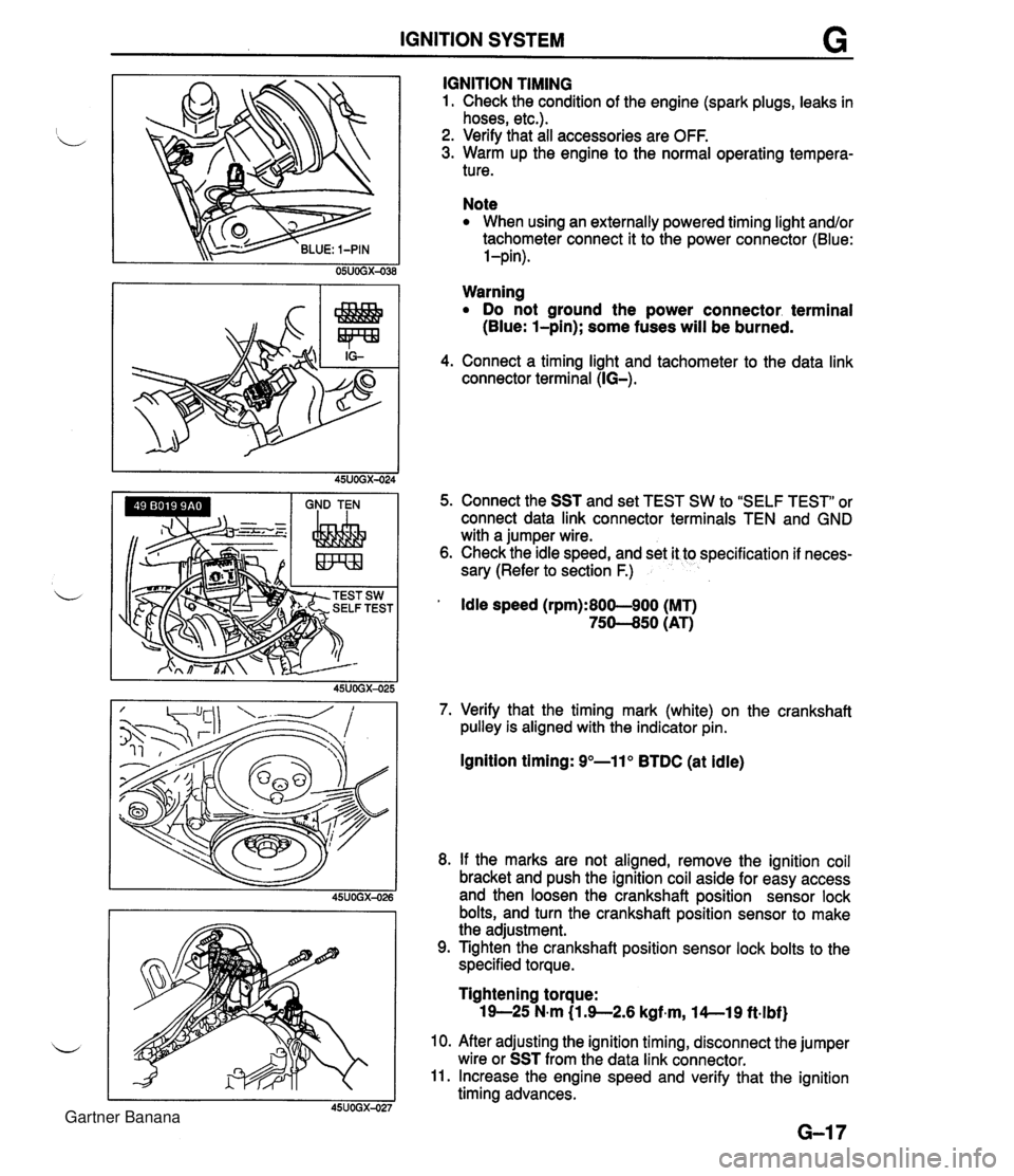
IGNITION SYSTEM G GND TEN I I I IGNITION TIMING 1. Check the condition of the engine (spark plugs, leaks in hoses, etc.). 2. Verify that all accessories are OFF. 3. Warm up the engine to the normal operating tempera- ture. Note When using an externally powered timing light and/or tachometer connect it to the power connector (Blue: l-pin). Warning Do not ground the power connector. terminal (Blue: l-pin); some fuses will be burned. 4. Connect a timing light and tachometer to the data link connector terminal (IG-). 5. Connect the SST and set TEST SW to "SELF TEST" or connect data link connector terminals TEN and GND with a jumper wire. 6. Check the idle speed, and set it to specification if neces- sary (Refer to section F.) ' Idle speed (rpm):800-900 (MT) 75-50 (AT) 7. Verify that the timing mark (white) on the crankshaft pulley is aligned with the indicator pin. Ignition timing: 9"-11" BTDC (at idle) 8. If the marks are not aligned, remove the ignition coil bracket and push the ignition coil aside for easy access and then loosen the crankshaft position sensor lock bolts, and turn the crankshaft position sensor to make the adjustment. 9. Tighten the crankshaft position sensor lock bolts to the specified torque. Tightening torque: 19-25 N-m (1 3-2.6 kgf~m, l4--19 ft.lbf) 10. After adjusting the ignition timing, disconnect the jumper wire or SST from the data link connector. 11. Increase the engine speed and verify that the ignition timing advances. Gartner Banana
Page 325 of 1708

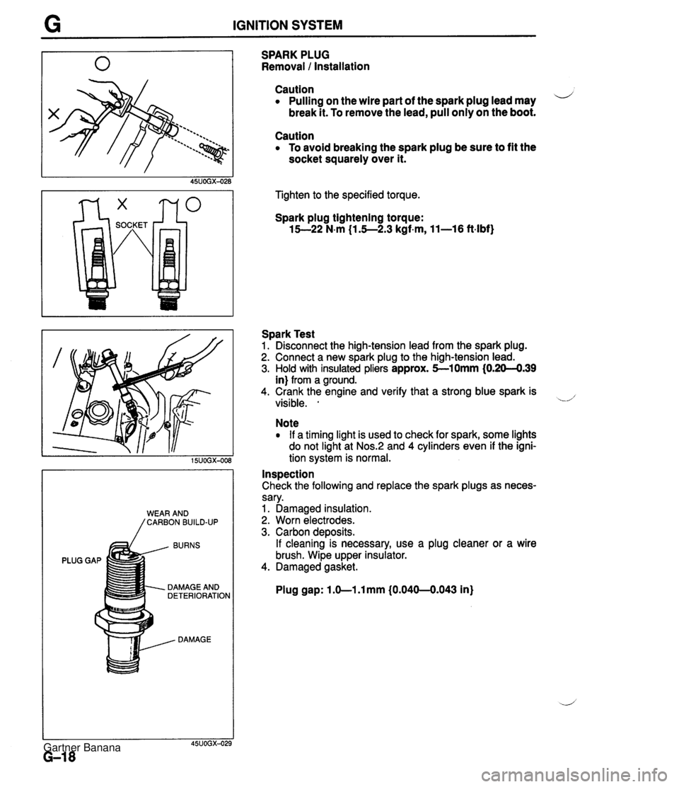
G IGNITION SYSTEM BURNS PLUG GAP DAMAGE AND DETERIORATION DAMAGE SPARK PLUG Removal 1 Installation Caution Pulling on the wire part of the spark plug lead may i/ break it. To remove the lead, pull only on the boot. Caution To avoid breaking the spark plug be sure to fit the socket squarely over it. Tighten to the specified torque. Spark plug tightening torque: 15--22 N-m (1.5--2.3 kgf-m, 11-16 ft-lbf) Spark Test 1. Disconnect the high-tension lead from the spark plug. 2. Connect a new spark plug to the high-tension lead. 3. Hold with insulated pliers approx. 5-10mm (0.20-4.39 in) from a ground. 4. Crank the engine and verify that a strong blue spark is visible. . -.d' Note If a timing light is used to check for spark, some lights do not light at Nos.:! and 4 cylinders even if the igni- tion system is normal. Inspection Check the following and replace the spark plugs as neces- sary. 1. Damaged insulation. 2. Worn electrodes. 3. Carbon deposits. If cleaning is necessary, use a plug cleaner or a wire brush. Wipe upper insulator. 4. Damaged gasket. Plug gap: 1 .O-1 .l mm (0.040-0.043 in) Gartner Banana
Page 736 of 1708

OUTLINE OUTLINE SPECIFICATIONS Front Suspension - Transmission item (Stabilizer Specifications MT I AT - I Susoension tvoe I . , . , I . , Shock absorber Cylindrical double acting, low-pressure-gas charged I Double-wishbone TY pe Torsion bar Coil spring I - Diameter mm linl I 20.0 10.79) Identification mark color 19.0 (0.75) White Wire diameter mm (in) Coil inner diameter mm {in) I Blue Free length mm {in) Coil number 11 .O (0.43) 83 i3.27) 11 .O (0.43) 83 (3.27) 292.5 (1 1 32) 6.32 3 +. 3 (0.12 + 0.12) 0°18' + 18' Total toe-in I - I 35UORX-001 Rear Suspension 302.0 (1 1.89) 6.32 mm {in) degree Total toe-in (per side) 1 degree Front wheel alignment (Unladedt1) 0°09' +. 09' Caster anglee3 4"26' +. 45' Kingpin angle 11 "20' Maximum steering angle Transmission Specifications MT I AT Item Differential - Suspension type Inner Outer "TORSEN" LSD 1 Standard Double-wishbone Coil springs 370 23' a 2" 32" 32' -t 2" Camber anglee2 Torsion bar 12.0 (0.47) 1 11.0 (0.43) 1 11 .O (0.43) Cylindrical double acting, low-pressure-gas charged - Stabilizer Identification mark color Wire diameter mm {in) 0°24' + 45' Type Diameter mm {in) I Coil number I 7.68 I 7.96 I Shock absorber Yellow 10.1 {0.40} Coil inner diameter mm {in) Free length mm {in) Green 10.2 {0.40) 35UORX-002 *I Fuel tank full; radiator coolant and engine oil at specified levels; spare tire, jack, and tools in designated positions. '2 Difference between left and right must not exceed I O. '3 Difference between left and right must not exceed 1'30'. "TORSEN" is a registered trademark of ZEXEL-GLEASON USA.INC 83 I3.27) 348.5 j13.72) Rear wheel alignment (Unladed*') 83 (3.27) 356.5 (1 4.04) Total toe-in Total toe-in (per side) mm (in) degree degree 3 -c 3 (0.12 + 0.121 0°18' + 18' 0°09' + 09' Camber angle*2 -0°43' 2 30' Gartner Banana
Page 856 of 1708

FUSE SPECIFICATIONS Main Fuse Block u I Fuse Amperes Protected circuit HEAD INJ MAIN BTN 30A 30A COOLING FAN (AD FAN) 1 ABS I 60A I Antilock brake svstem I Headlight relay, Headlight switch Alternator, Diagnostic module (for air bag system) 80A 40A ST SIG RETRACTOR Fuse Box No.1 Except circuits protected in main fuse block: INJ 30A, HEAD 30A, RETRACTOR 30A TNS relay, Headlight switch 30A 20A EGI main relay, Coolant fan relay A/C relay 10A 30A Park l Neutral switch, Circuit-opening relay Retractable headlight actuator Fuse ENGINE METER (POWER WIND) Amperes 15A WIPER TAIL ROOM I 10A I PCME, Key reminder switch, Audio unit I Protected circuit EGI main relay, Coolant fan relay 15A 30A STOP HAZARD CIGAR 15A I Cigarette lighter, Audio unit 1 Instrument cluster, Turn signal switch, Timer and buzzer unit, Cruise control main switch Power window switch 20A 15A Fuse Box No.2 Blower switch, Wiper switch Taillights, Side marker lights, License plate lights, Parking lights 15A 15A Fuse Amperes Protected circuit I Stoplight switch, Horn switch, Cruise control unit Flasher unit Fuse Color Code (DEFOG) (ANTENNA) I Fuse amperes I Color code Fuse type 25UOTX-013 20A 20A I I 10A Red 1 I Rear window defroster Power antenna Plate type 15A 20A Light blue Yellow 30A 30A 80A Light green Pink Black Cartridge type Gartner Banana
Page 1005 of 1708

T SRS AIR BAG SYSTEM GENERALPROCEDURES Before Servicing 1. Deactivate the audio antitheft system, if installed. (Refer to page T-120.) 2. Disconnect the negative battery cable. 3. Remove the lower panel. 4. Disconnect the orange and blue clock spring connec- tors. 5. Remove the glove compartment. 6. Disconnect the orange and blue passenger-side air bag module connectors. I , 46UOTXd21 TROUBLESHOOTING Troubleshootinn Procedure The air bag diagnostic module has a self-diagnosis function that flashes or illuminates the AIR BAG sys- tem warning light to indicate trouble in the air bag system. The trouble can be determined by the warning light illumination or flashing pattern. If the light does not illuminate but the system still has trouble, a warn- ing buzzer will sound 5 cycles of 5 times each. . . Flowchart I START Troubleshoot warning light circuit Does AIR BAG system warning light illuminate for 4-8 secs and I I Yes t Refer to service code table and troubleshoot system Press horn switch while turning steering wheel. Does horn sound? I I I Yes Reconnect connectors Are air bag module and horn switch connectors properly con- nected to clock spring connec- tor? Yes I I I I Troubleshooting horn circuit - Gartner Banana
Page 1012 of 1708

SRS AIR BAG SYSTEM L Possible cause Defective air bag module(s) Defective clock spring Defective S-sensor Defective D-sensor Defective diagnostic Defective wiring harness Step 1 Carry out "Before Servicing" procedure under GENER- AL PROCEDURES, page T-160. Service Code 13 Flowchart No.3 Step 2 1. Connect the negative battery cable. 2. Turn the ignition switch ON and check the service code. Symptom Step 3 Service code 13 Other Warning Handling the air bag module improperly can acci- dently deploy the air bag, which may seriously in- jure you. Read SERVICE WARNINGS, page T-159, before handling the air bag module. Action Go to Step 5 Go to Step 3 1. Turn the ignition switch to LOCK. 2. Disconnect the negative battery cable. 3. Remove the driver-side air bag module. (Refer to page T-206.) 4. Connect the blue and orange clock spring connectors. 5. Connect the negative battery cable. 6. Turn the ignition switch to ON and check the service code. I Service code I Action 1 13 Other Replace combination switch (Refer to page T-19) Go to step 4 Gartner Banana
Page 1013 of 1708

T SRS AIR BAG SYSTEM Step 4 1. Turn the ignition switch to LOCK. 2. Disconnect the negative battery cable. 3. Connect the blue and orange passenger-side air bag d module connectors. 4. Connect the negative battery cable. 5. Turn the ignition switch to ON and check the service code. I Service code I Action I I 13 Replace passenger-side air bag module (Refer to page T-207) I I mer I Replace driver-side air bag module (Refer to ~aae T-2061 I No I Go to Step 6 Step 5 1. Turn the ignition switch to LOCK. 2. Disconnect the diagnostic module connectors. 3. Check for continuity between terminal 2F (GY) of the diagnostic module connector and ground. Step 6 Check for continuity between terminal 2G (GN) of the diagnostic module connector and ground. I Continuity Action d Continuity Yes Step 7 Check for continuity between terminal 20 (GNV) of the diagnostic module connector and ground. Action Replace wiring harness Yes No Replace wiring harness Go to Step 7 I NO I GO to Step 9 ~d Continuity Yes Action Go to Step 8 Gartner Banana
Page 1014 of 1708

SRS AIR BAG SYSTEM Step 8 1. Disconnect the orange and blue S-sensor connectors. 2. Check for continuity between terminal C of the S-sensor and ground. Continuity Action 1 Yes No Step 10 1. Disconnect the suspect sensor connector. 2. Measure the resistance between terminal A of the sen- sor and ground. Replace S-sensor (Refer to page T-213) Replace wiring harness Step 9 Measure the resistance between terminal 1 C (BRIG), 1 A (BRIR), and 2L (BRIB) of the diagnostic module connec- tor and ground. Resistance k&2 Other Other I Replace sensor I Action Replace diagnostic module (Refer to page T-208) Suspect sensor: Terminal 1 C -+ right D-sensor Terminal 1 A -+ Center D-sensor Terminal 2L -+ left D-sensor Go to Step 10 Measure 1.18 kn Action Replace wiring harness Gartner Banana
Page 1015 of 1708

T SRS AIR BAG SYSTEM Possible cause i/ Defective S-sensor Defective wiring harness Defective diagnostic module Step 1 Carry out "Before Servicing" procedure under GENER- AL PROCEDURES, page T-160. Service Code 21 Flowchart No.4 Step 2 1. Disconnect the diagnostic module connector. 2. Check for continuity between terminal 1 E (RIB) of the Symptom connector and ground. Step 3 1. -Disconnect the orange and blue S-sensor connector. 2. Check for continuity between terminal A of the S-sensor and ground. I Continuity I Action Continuity Yes No Action Replace diagnostic module (Refer to page T-208) Go to Step 3 Yes No Replace wiring harness Replace S-sensor (Refer to page T-213) Gartner Banana
Page 1016 of 1708

SRS AIR BAG SYSTEM T Flowchart N0.5 I Symptom I Service Code 22 Possible cause Defective wiring harness Defective S-sensor Defective diagnostic module Step 1 Carry out "Before Servicing" procedure under GENER- AL PROCEDURES, page T-160. Step 2 1. Disconnect the diagnostic module connector. 2. Check for continuity between terminal 1 H (GIB) and 2D (GMI) of the diagnostic module connector. Continuity Yes Step 3 1. Disconnect the orange and blue S-sensor connectors. 2. Check for continuity between terminal B and D of the S- sensor. Continuity I Action I Action Go to Step 3 I No Replace diagnostic module (Refer to page T-208) Yes No Replace S-sensor (Refer to page T-213) Replace wiring harness Gartner Banana