maintenance MAZDA MX-5 1994 User Guide
[x] Cancel search | Manufacturer: MAZDA, Model Year: 1994, Model line: MX-5, Model: MAZDA MX-5 1994Pages: 1708, PDF Size: 82.34 MB
Page 36 of 1708

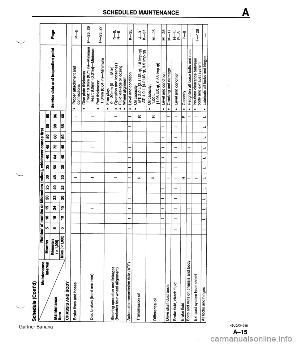
SCHEDULED MAINTENANCE A - CO - c E z2 : $i 2 5 2 m mr 5 z L-O g 2 - 3:: =n - - Gartner Banana
Page 37 of 1708

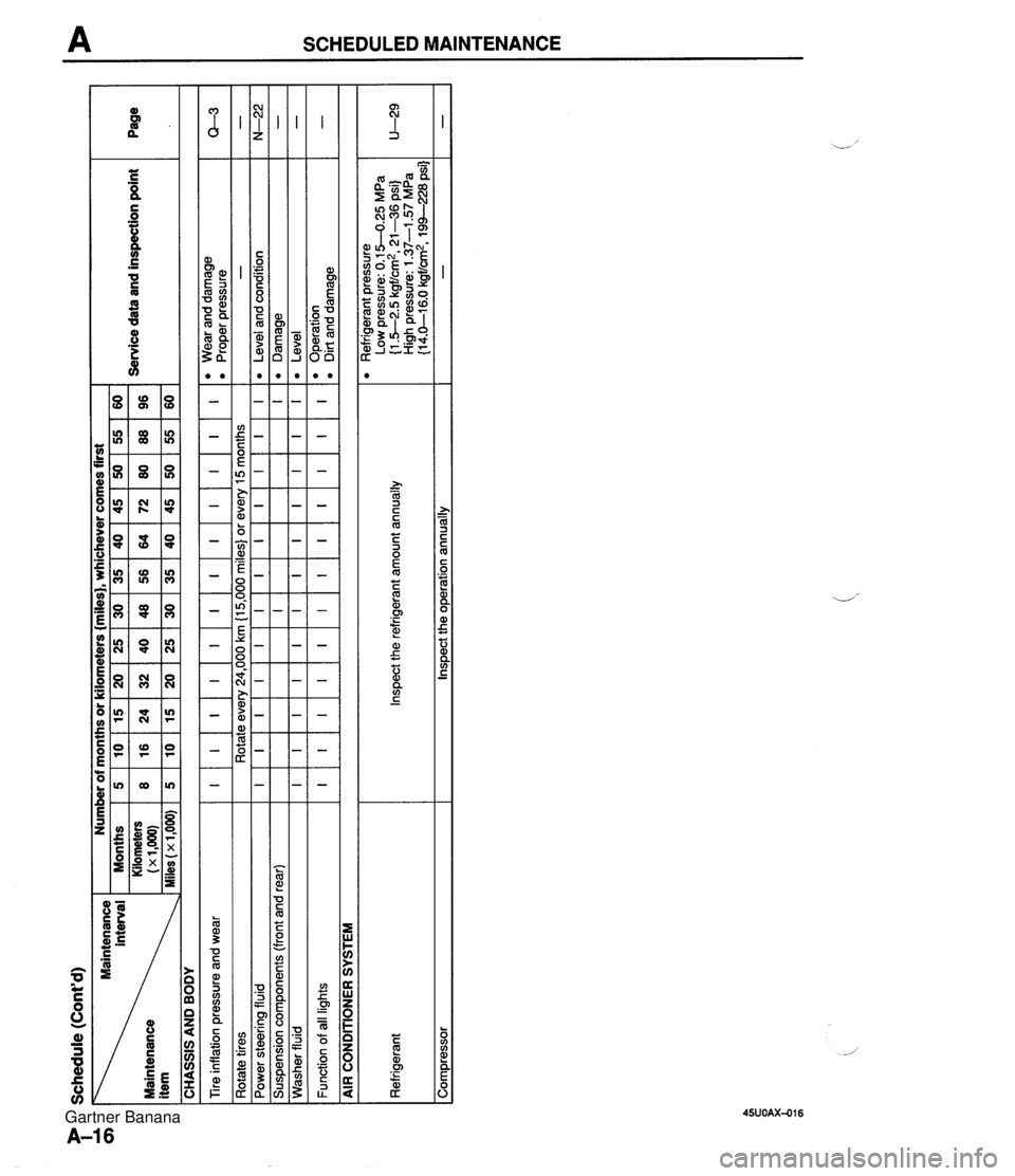
A SCHEDULED MAINTENANCE Gartner Banana
Page 38 of 1708

Before beginning any service procedure. refer to section T of this manual for air bag system service warnings and audio antitheft system alarm conditions . ENGINE INDEX ............................. B- 2 OUTLINE .......................... B- 3 SPECIFICATIONS ................ B- 3 TROUBLESHOOTING GUIDE ........ B- 3 ENGINE TUNE-UP .................. 8- 5 PREPARATION ................... B- 5 ENGINE OIL ..................... B- 5 ENGINE COOLANT ............... B- 5 DRIVE BELT ..................... 8- 6 HLA TROUBLESHOOTING GUIDE . 8- 8 IGNITION TIMING. IDLE SPEED .... B- 8 COMPRESSION .................... 8-10 INSPECTION ..................... B-10 ON-VEHICLE MAINTENANCE ....... B-11 PREPARATION ................... B-11 TIMING BELT ..................... 8-12 CYLINDER HEAD GASKET ........ B-16 H LA ............................. 8-20 FRONT OIL SEAL ................. 8-24 REAR OIL SEAL .................. 8-26 REMOVAL ......................... 8-28 PROCEDURE .................... B-28 ENGINE STAND MOUNTING ......... 8-32 PREPARATION ................... 8-32 PROCEDURE .................... B-33 DISASSEMBLY ..................... B-35 PREPARATION ................... 8-35 AUXILIARY PARTS ............... 8-36 TIMING BELT ..................... 8-37 CYLINDER HEAD ................. 8-39 CYLINDER BLOCK (EXTERNAL PARTS) ............. 8-42 CYLINDER BLOCK .............. (INTERNAL PARTS) 8-44 .............. INSPECTION I REPAIR 8-47 ................... PREPARATION 8-47 ................. CYLINDER HEAD 8-47 .............. VALVE MECHANISM 8-48 ...................... CAMSHAFT B-51 HLA ............................. 8-53 ............... CYLINDER BLOCK B-53 .......................... OIL JET B-54 PISTON. PISTON RING. AND ..................... PISTON PIN 8-55 CONNECTING ROD .............. B-56 ................... CRANKSHAFT 8-57 BEARING ........................ 8-57 TIMING BELT ..................... 8-58 TENSIONER. IDLER .............. 8-58 TENSIONER SPRING ............. 8-58 PULLEY ......................... 8-58 ........................ ASSEMBLY 8-59 ................... PREPARATION 8-59 CYLINDER BLOCK (INTERNAL PARTS) .............. B-60 CYLINDER BLOCK (EXTERNAL PARTS) ............. B-65 CYLINDER HEAD ................. B-69 TIMING BELT ..................... 8-73 ............... AUXILIARY PARTS 8-77 ..... ENGINE STAND DISMOUNTING 8-81 .................... PROCEDURE 8-81 INSTALLATION ..................... 8-83 .................... PROCEDURE 843 45UOBX-001 Gartner Banana
Page 40 of 1708

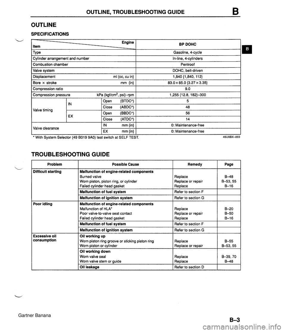
OUTLINE, TROUBLESHOOTING GUIDE OUTLINE SPECIFICATIONS Engine Item Tv~e BP DOHC Gasoline, 4-cvcle . . I -, Dis~lacement ml kc. cu inl I 1.840 (1.840. 11 2) I Cylinder arrangement and number Combustion chamber Valve system Bore x stroke mm {in) I 83.0 x 85.0 (3.27 x 3.35) I In-line, 4-cylinders Pentroof DOHC, belt-driven Com~ression ratio I 9.0 I Compression pressure kPa (kgf/cm2, psi)-rpm .- . 1 open (BTDCO) 1,255 {I 2.8, 182)-300 5 Valve timing TROUBLESHOOTING GUIDE tX Valve clearance Problem .. . -. . Difficult starting ' With System Selector (49 B019 9AO) test switch at SELF TEST. 45uo~x-003 Close (ATDCO) IN mm {in) EX mm {in) Poor idling Close (ABDCO) Open (BBDCO) 14 0: Maintenance-free 0: Maintenance-free Excessive oil consumption 48 56 Possible Cause Malfunction of engine-related components Burned valve Worn piston, piston ring, or cylinder Failed cylinder head gasket Malfunction of fuel system Malfunction of ignition system Malfunction of engine-related components Malfunction of HLA' Poor valve-to-valve seat contact Failed cvlinder head aasket Oil leakage I Refer to section D I I Remedy Malfunction of fuel system Malfunction of ignition system Oil working up Worn piston ring groove or sticking piston ring Worn piston or cylinder Oil working down Worn valve seal Worn valve stem or guide Page Replace Replace or repair Replace Refer to section F Refer to section G Replace Replace or repair Re~lace 8-48 B-53,55 B-1 6 B-20 B-50 B-1 6 Refer to section F Refer to section G Replace Replace or repair Replace Replace B-55 B-53,55 B-39,70 8-48 Gartner Banana
Page 48 of 1708

ON-VEHICLE MAINTENANCE B ON-VEHICLE MAINTENANCE PREPARATION L SST 49 DO11 102 Lock tool, crankshaft Shaft (Part of 49 E011 1AO) Collar (Part of 49 E011 1 AO) Warninq For removal / installat ion of timing belt pulley For prevention of engine rotation For prevention of engine rotation 49 EOl 1 105 Stopper (Part of 49 EOll 1AO) 49 EOll 1 A0 Ring gear brake set For prevention of engine rotation For prevention of engine rotation ~onhuous exposure with USED engine oil has caused skin cancer in laboratory mice. Protect your skin by washing with soap and water immediately after this work. 49 SEO1 310 A Centering tool, clutch disc For installation of clutch disc Gartner Banana
Page 49 of 1708

B ON-VEHICLE MAINTENANCE TIMING BELT Removal / lnstallation 1. Disconnect the negative battery cable. 2. Drain the engine coolant. 3. Remove the under cover. 4. Remove in the order shown in the figure, referring to Removal Note. 5. Install in the reverse order of removal, referring to lnstallation Note. (80-110 kgfmn, 7.9-10.7 Nm 13-17 Nm (125-175 kgfcm, 109-151 In4bf) Nm (kgfm, ft4bf) 45UOBX425 1. Air intake pipe 12. Spark plug 2. Upper radiator hose Removal / Installation ......... section G 3. Water hoses (Connected to thermostat 13. PCV valve housing) 14. Cylinder head cover 4. PIS andlor A/C drive belt 15. Upper timing belt cover Removal 1 Installation ....... page B- 6 16. Middle timing belt cover 5. Alternator drive belt 17. Lower timing belt cover Removal / Installation ....... page 5 6 18. Timing belt 6. Water pump pulley Removal Note ............. page B-13 7. Plate Installation Note ........... page B-14 8. Crankshaft pulley Inspection ................. page 8-58 9. Pulley lock bolt 19. Tensioner, tensioner spring Removal Note ............. page B-13 Installation Note ........... page B-14 /' Installation Note ........... page 51 5 Inspection ................. page 558 10. Pulley boss 20. Idler 11. Ignition coil and high-tension lead Inspection ................. page 8-58 Gartner Banana
Page 50 of 1708

ON-VEHICLE MAINTENANCE B IDLER L ROTATION ARROW - Removal Note Pulley lock bolt 1. Hold the pulley boss with the SST. 2. Using the SST, loosen the pulley lock bolt. 3. Remove the bolt and the pulley boss. Timing belt 1. Install the pulley boss. 2. Install the pulley lock bolt. 3. Turn the crankshaft to align the timing marks. 4. Do not turn the crankshaft after aligning the timing marks. 5. Remove the pulley lock bolt and pulley boss. 6. Mark the timing belt rotation for proper reinstallation. 7. Loosen the tensioner lock bolt and pry the tensioner out- ward with a bar. 8. Tighten the lock bolt with the tensioner spring fully ex- tended. 9. Remove the timing belt. Gartner Banana
Page 51 of 1708

ON-VEHICLE MAINTENANCE Installation Note Tensioner and tensioner spring 1. Install the tensioner and the tensioner spring. 2. Protect the tensioner with a rag. Pry the tensioner out- -,, ward with a bar. 3. Temporarily tighten the tensioner lock bolt with the ten- sioner spring fully extended. Timing belt 1. Verify that the timing belt pulley mark is aligned with the timing mark. 2. Verify that the camshaft pulley marks are aligned with the seal plate marks. E for intake side, and I for exhaust side. 3. Install the timing belt so that there is no looseness at the idler side or between the camshaft pulleys. 4. Install the pulley boss and pulley lock bolt. 5. Turn the crankshaft two turns clockwise and face the pin on the pulley boss upright. Do not turn the crankshaft counterclockwise. 6. Verify that the camshaft pulley marks are again aligned with the seal plate marks. If not aligned, remove the timing belt and repeat from tensioner installation. 7. Turn the crankshaft 1 and 516 turns clockwise and align the timing belt pulley mark with the tension set mark for proper timing belt tension adjustment. 8. Using the SST, loosen the pulley lock bolt and remove the bolt and pulley boss. Do not turn the crankshaft. 9. Verify that the timing belt pulley mark is aligned with the tension set mark. Gartner Banana
Page 52 of 1708

ON-VEHICLE MAINTENANCE B Stem After Installation 10. Loosen the tensioner lock bolt to apply spring tension to the timing belt. 11. Tighten the tensioner lock bolt. Tightening torque: 38-51 N-m (3.8-5.3 kgf.m, 28--38 ftlbf) 12. Install the pulley boss and pulley lock bolt. 13. Turn the crankshaft 2 and 116 turns clockwise and verify that the timing marks are correctly aligned. 14. Measure the timing belt deflection by applying moderate pressure 98 N (10 kgf, 22 Ibf) midway between the cam- shaft pulleys. If the deflection is not correct, repeat from Step 10 above. Deflection: 9.0-11.5mm (0.36-4.45 in) at 98 N (10 kgf, 22 Ibf) Pulley lock bolt Hold the crankshaft with the SST and tighten the pulley lock bolt. Tightening torque: 157-166 N.m (16-17 kgf.m, 116-122 ftlbf) 1. till the radiator with specified amount and type of engine coolant. (Refer to section E.) 2. Connect the negative battery cable. 3. Start the engine and check, and if necessary, adjust the ignition timing. Gartner Banana
Page 53 of 1708

ON-VEHICLE MAINTENANCE CYLINDER HEAD GASKET Replacement Warning e Fuel line spills and leaks are dangerous. Fuel can ignite and cause serious injuries or death and damage. Fuel can also irritate skin and eyes. To prevent this, always complete the "Fuel Line Safety Procedures" on section F. Fuel vapor is hazardous. It can very easily ignite, causing serious injury and damage. Always keep sparks and flames away from fuel. 1. Disconnect the negative battery cable. 2. Drain the engine coolant. (Refer to section E.) 3. Remove in the order shown in the figure, referring to Removal Note. 4. Install in the reverse order of removal, referring to Installation Note. Gartner Banana