boot MAZDA MX-5 1994 Workshop Manual
[x] Cancel search | Manufacturer: MAZDA, Model Year: 1994, Model line: MX-5, Model: MAZDA MX-5 1994Pages: 1708, PDF Size: 82.34 MB
Page 26 of 1708
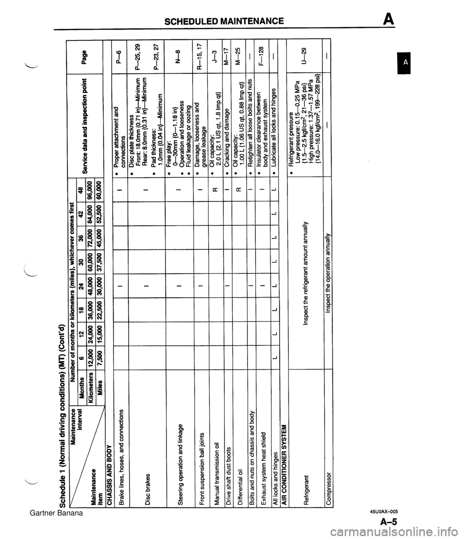
Schedule 1 (Normal driving conditions) (MT) (Cont'd) Maintenance 1 Number of months or kilometers {miles), whichever comes first I I 1 Months 1 6 18 124 130 136 142148 Service data and inspection point 36,000 1 48,000 1 60,000 1 72,000 1 84,000 1 96,000 Maintenance item I CHASSIS AND BODY Brake lines, hoses, and connections Disc plate thickness Front: 18.0mm (0.71 in)--Minimum I I 1 near: 8.0mm {o31 inFMnimum P-6 I Disc brakes I Pad thickness: I I I I I ~10mrn~0.04inMlinimum I Proper attachment and connections Steering operation and linkage I I I I I I I 0-3'0mm (0-1.1 8 in) Operation and looseness Fluid leakaae or oozina I I Front suspension ball joints I I Free play: I I I I I I I - - Manual transmission oil I I I I I , I Damage, looseness and I grease leakage Oil capacity: 2.0 L (2.1 US at. 1.8 Imp qtJ Ill I I I I I Cracking and damage I , I Oil capacity: I I I Differential oil I Drive shaft dust boots I Bolts and nuts on chassis and body I I I n I 1 .OO L {I .06 US qt, 0.88 Imp qt} Ill Exhaust system heat shield I I I I 1 Retiahten all loose bolts and nuts L All locks and hinges lLlLl - AIR CONDITIONER SYSTEM I L Refrigerant pressure Low pressure: 0.1 5-0.25 MPa {I -52.5 kgf/cm2, 21-36 psi) High pressure: 1.37-1 -57 MPa {I 4.0-1 6.0 kgf/cm2, 1 XI-228 psi] - L Corn~ressor I lnswct the o~eration annuallv Refrigerant L Inspect the refrigerant amount annually L I L " Insulator clearance between body and exhaust system Lubricate all locks and hinges F-128 - Gartner Banana
Page 28 of 1708
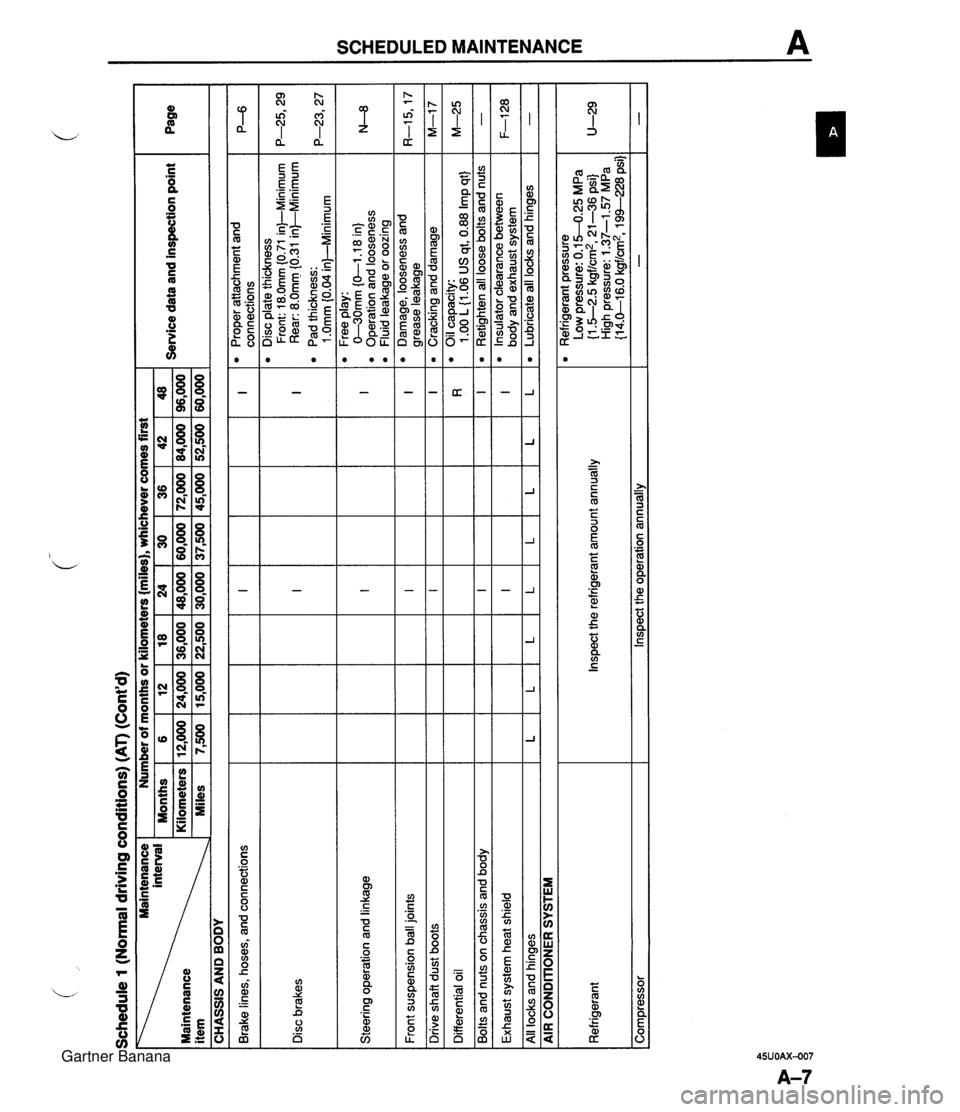
Schedule 1 (Normal driving conditions) (AT) (Cont'd) - .. .. Brake lines, hoses, and connections -- Front suspension ball joints Page I Disc brakes Steering operation and linkage I I 1 I I I I Drive shaft dust boots Ill CHASSIS AND BODY Service data and inspection point Maintenance Number of months or kilometers {miles), whichever comes first I I Differential oil I interval Months Maintenance Kilometers item Miles Exhaust system heat shield I 36 72,000 45,000 I I I I I I I I I 1 I I I I All locks and hinaes lLlLlLlLlLlLlL 6 12,000 7,500 Bolts and nuts on chassis and body - AIR CONDIIONER SYSTEM 42 84,000 52,500 I Ill 12 24,000 15,000 96,000 60,000 Proper attachment and connections Disc plate thickness Front: 18.0mm (0.71 in)-Minimum Rear: 8.0mm f0.31 in)--Minimum Pad thickness: 1 .Omm 10.04 inl-Minimum .-- Free play: C-30mm (0-1 .I 8 in) Operation and looseness Fluid leakage or oozing 18 36,000 22,500 Refrigerant Compressor Damage, looseness and arease leakaae Inspect the refrigerant amount annually Inspect the operation annually 24 48,000 30,000 30 60,000 37,500 Cracking and damage Oil capacity: 1 .OO L 11.06 US at. 0.88 Irn~ at} M-17 M-25 Retighten all loose bolts and nuts Insulator clearance between bodv and exhaust system Refrigerant pressure Low pressure: 0.1 5-0.25 MPa (1 .5-2.5 kgf/:, 21-36 psi) 1 LJ: High pressure: 1.37-1.57 MPa {I 4.0-1 6.0 kgf/cm2, 194--228 psi) - F-128 Lubricate all locks and hinges - Gartner Banana
Page 31 of 1708

2 (Unique driving conditions) (MT) (Cont'd) Number of months or kilometers miles), whichever comes first 24 28 32 36 40 44 48 48 56 64 72 80 88 96 Service data and inspection point Page Maintenance interval Maintenance item .# CHASSIS AND BODY Proper attachment and connections Brake lines, hoses, and connections IIII Disc brakes I Steering operation and linkage Disc plate thickness Front: 18.0mm (0.71 inkMinimum Rear: 8.0mm I0.31 in)--Minimum Pad thickness: 1 .Omm 10.04 inbMinimum Free play: O-30mm {0-1.18 in) Operation and looseness Fluid leakage or oozing Front suspension ball joints 1111 Damage, looseness and arease leakaae I I I I Drive shaft dust boots Cracking and damage Manual transmission oil Oil capacity: 2.0 L (2.1 US at, 1.8 I~D at1 Differential oil Oil capacity: 1 .OO L(1.06 US qt, 0.88 Imp qt} Retighten all loose bolts and nuts I I I Bolts and nuts on chassis and body Exhaust system heat shield Insulator clearance between bodv and exhaust svstem I I I I All locks and hinges ILlLlLlL Lubricate all locks and hinges - I AIR CONDITIONER SYSTEM ~p - ~-~p- Refrigerant Inspect the refrigerant amount annually Refrigerant pressure Low pressure: 0.1 5-0.25 MPa {I S-2.5 kgf/cm2, 21 -36 psi} High pressure: 1.37-1 57 MPa (1 4.0-1 6.0 kgf/cm2, 194-228 psi) Comoressor I lnsoect the ooeration annuallv I I - Gartner Banana
Page 33 of 1708

I Brake lines. hoses, and connections Ill Schedule 2 (Unique driving conditions) (AT) (Cont'd) Disc brakes Steering operation and linkage I Front suspension ball joints 111 Page I Drive shaft dust boots I I I CHASSIS AND BODY Service data and inspection point Maintenance Number of months or kilometers {miles}, whichever comes first I Differential oil 111 I Bolts and nuts on chassis and body 111 48 96 60 I Exhaust system heat shield Ill interval Months Kilometers Maintenance (x1,OOO) Miles(x1,OOO) All locks and hinges AIR CONDIVONER SYSTEM 12 24 15 4 8 5 Disc plate thickness Front: 18.0mm (0.71 in)-Minimum Rear: 8.0mm i0.31 in)-Minimum Pad thickness: 1 .Omm (0.04 in)--Minimum Free play: 0-30mm {O-1 .I 8 in} Operation and looseness Fluid leakage or oozing 16 32 20 8 16 10 P--6 I l Oil capacity: I I I I 1 I 1.00 L 11-06 US at. 0.88 lm~ at I M-25 l Proper attachment and connections I I I I I I I I 7, .' , Ill I 1 I I Retighten all loose bolts and nuts I - 20 40 25 l Damage, looseness and grease leakage Cracking and damage Insulator clearance between I I I I I1Iob odv and exhaust svstem 28 56 35 24 48 30 L 1 L I L I L 1 L 1 L 1 Lubricatealllocksandhinges I - Refrigerant 32 64 40 Inspect the refrigerant amount annually 36 72 45 l Refrigerant pressure Low pressure: 0.1 5-0.25 MPa (1.5-2.5 kgf/cm2, 21-36 psi} High pressure: 1.37-1 57 MPa {I 4.0-1 6.0 kgfld, 19%-228 psi] - I 40 80 50 Compressor 44 88 55 Inspect the operation annually Gartner Banana
Page 325 of 1708
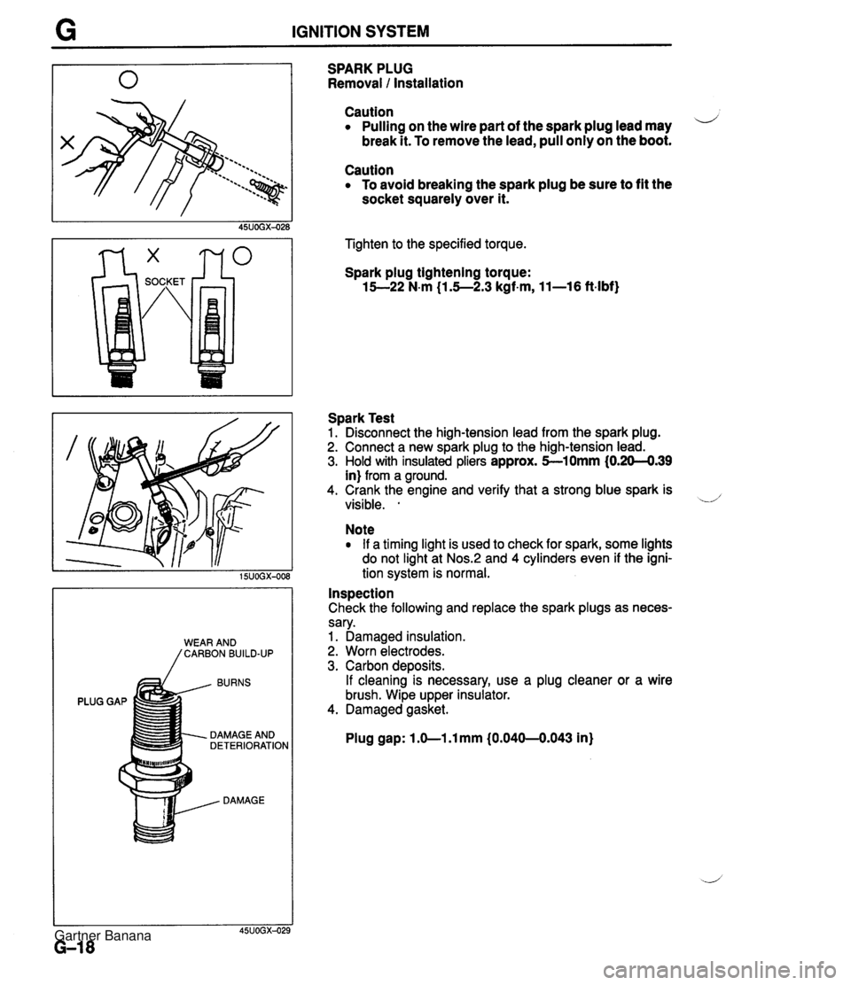
G IGNITION SYSTEM BURNS PLUG GAP DAMAGE AND DETERIORATION DAMAGE SPARK PLUG Removal 1 Installation Caution Pulling on the wire part of the spark plug lead may i/ break it. To remove the lead, pull only on the boot. Caution To avoid breaking the spark plug be sure to fit the socket squarely over it. Tighten to the specified torque. Spark plug tightening torque: 15--22 N-m (1.5--2.3 kgf-m, 11-16 ft-lbf) Spark Test 1. Disconnect the high-tension lead from the spark plug. 2. Connect a new spark plug to the high-tension lead. 3. Hold with insulated pliers approx. 5-10mm (0.20-4.39 in) from a ground. 4. Crank the engine and verify that a strong blue spark is visible. . -.d' Note If a timing light is used to check for spark, some lights do not light at Nos.:! and 4 cylinders even if the igni- tion system is normal. Inspection Check the following and replace the spark plugs as neces- sary. 1. Damaged insulation. 2. Worn electrodes. 3. Carbon deposits. If cleaning is necessary, use a plug cleaner or a wire brush. Wipe upper insulator. 4. Damaged gasket. Plug gap: 1 .O-1 .l mm (0.040-0.043 in) Gartner Banana
Page 347 of 1708

H CLUTCH RELEASE CYLINDER CLUTCH RELEASE CYLINDER PREPARATION SST I I I 05UOHX-015 REMOVAL / INSTALLATION - 49 0259 7708 Wrench, flare nut Caution Clutch fluid will damage painted surfaces. If clutch fluid does get on a painted surface, wipe For disconnecting and connecting clutch pipe -. - it off immediately. 1. Remove in the order shown in the figure, referring to Removal Note. 2. Install in the reverse order of removal, referring to Installation Note. 1. Clutch pipe 3. Clutch release cylinder Removal Note .................. below Remove boot and check for fluid leakage .................. Installation Note ........... page H-13 Overhaul page H-13 ............... 2. Bolt Air Bleeding page H-13 Removal Note Clutch pipe 1. Disconnect the clutch pipe from the clutch release cylin- der by using the SST. 2. Plug the clutch pipe after removing, to avoid fluid leak- age. Gartner Banana
Page 348 of 1708

CLUTCH RELEASE CYLINDER H Installation Note Clutch pipe 1. Modify the clutch pipe tightening torque to allow for use of a torque wrench-SST combination. (Refer to section GI "Torque Formulas".) 2. Tighten the clutch pipe by using the SST. Tightening torque: 12.8-21.5 N-m (1 30-220 kgfam, 11%-190 in-lbf) Air Bleeding After installation, bleed the clutch system. (Refer to page H-9.) OVERHAUL 1. Disassemble in the order shown in the figure, referring to Disassembly Note. 2. lnspect all parts and repair or replace as necessary. Warning Using compressed air can cause dirt and other particles to fly out, causing injury to the eyes. Wear protective eye wear whenever using compressed air. 3. Wipe all parts, and clean all ports, passages, and inner parts with compressed air. 4. Assemble in the reverse order of disassembly. 1. Boot 5. Bleeder cap 2. Push rod 6. Bleeder screw 3. Piston and cup assembly 7. Steel ball Disassembly Note . . . . . . . . . . . . . . . below 8. Release cylinder body Inspect for wear, scoring, and cracks Inspect cylinder bore for scoring and corro- 4. Spring sion Disassembly Note Piston and cup assembly Warning Applying compressed air to the cylinder assem- bly can make the contents suddenly pop out, possibly causing injury. Hold a rag over the cylin- der opening when using compressed air. Remove the piston-and-cup assembly by applying com- pressed air through the clutch pipe installation hole. Gartner Banana
Page 350 of 1708
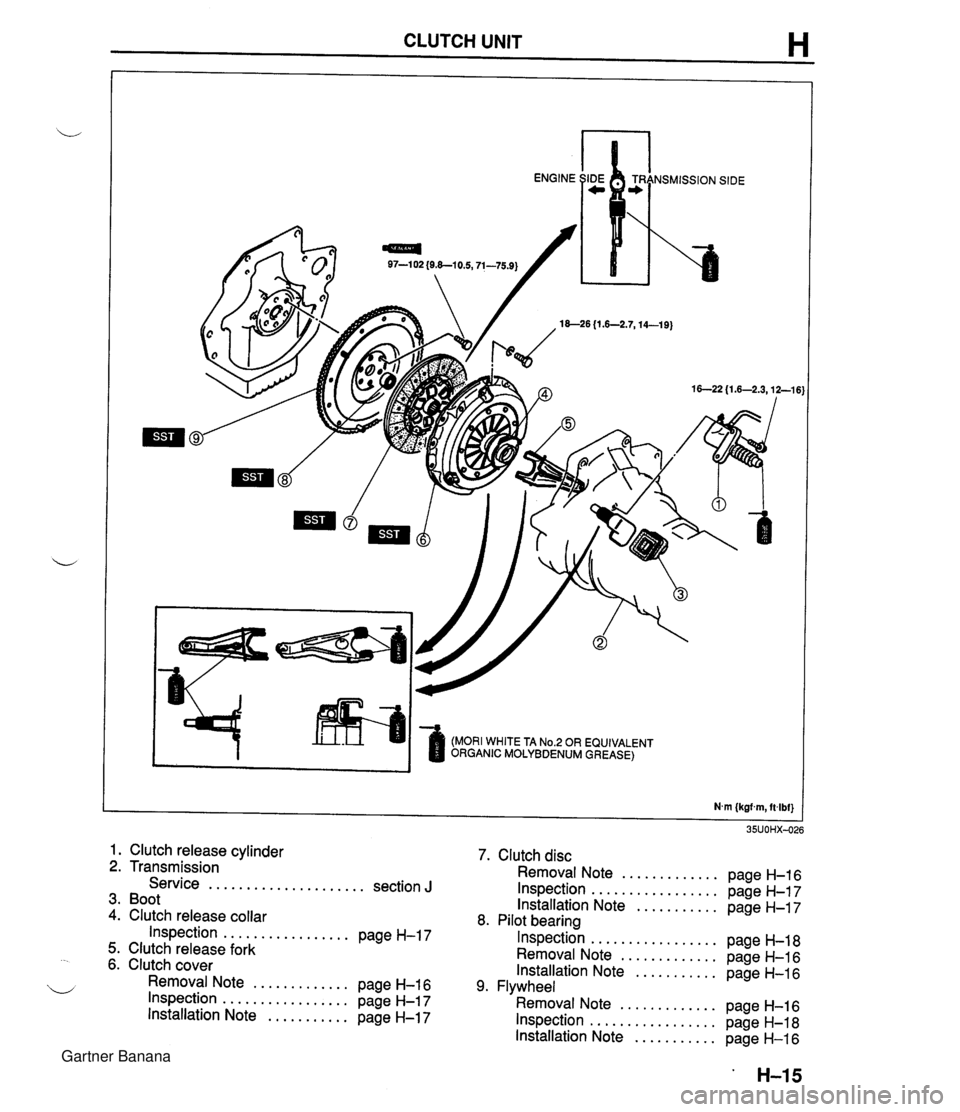
CLUTCH UNIT H 97-1 02 {O&-10.5,71-75.9) 18--26 {I .6-2.7,14-19) (MORI WHITE TA No.2 OR EQUIVALENT ORGANIC MOLYBDENUM GREASE) 1. Clutch release cylinder 2. Transmission Service ..................... section J 3. Boot 4. Clutch release collar Inspection ................. page H-17 5. Clutch release fork 6. Clutch cover Removal Note ............. page H-16 Inspection ................. page H-17 Installation Note ........... page H-17 7. Clutch disc Removal Note ............. page H-16 Inspection ................. page H-17 Installation Note ........... page H-17 8. Pilot bearing Inspection ................. page H-18 Removal Note ............. page H-16 Installation Note ........... page H-16 9. Flywheel Removal Note ............. page H-16 Inspection ................. page H-18 Installation Note ........... page H-16 Gartner Banana
Page 367 of 1708
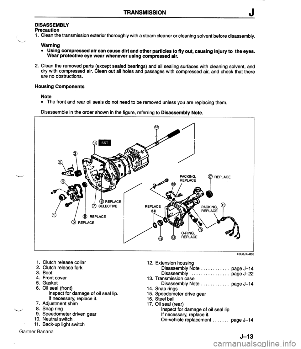
TRANSMISSION J DISASSEMBLY Precaution : 1. Clean the transmission exterior thoroughly with a steam cleaner or cleaning solvent before disassembly. b Warning Using compressed air can cause dirt and other particles to fly out, causing injury to the eyes. Wear protective eye wear whenever using compressed air. 2. Clean the removed parts (except sealed bearings) and all sealing surfaces with cleaning solvent, and dry with compressed air. Clean out all holes and passages with compressed air, and check that there are no obstructions. Housing Components Note The front and rear oil seals do not need to be removed unless you are replacing them. Disassemble in the order shown in the figure, referring to Disassembly Note. 1. Clutch release collar 2. Clutch release fork 3. Boot 4. Front cover 12. Extension housing Disassembly Note ............ page J-14 Disassembly ................ page J-22 13. Transmission case 5. Gasket Disassembly Note ............ pane J-14 6. Oil seal (front) lnspect for damage of oil seal lip. If necessary, replace it. 7. Adjustment shim 8. Snap ring 9. Speedometer driven gear 10. Neutral switch 11. Back-up light switch . - 14. Snap rings 15. Speedometer drive gear 16. Steel ball 17. Oil seal (rear) lnspect for damage of oil seal lip If necessary, replace it. On-vehicle replacement ....... page J-14 Gartner Banana
Page 397 of 1708
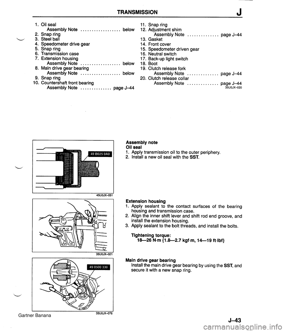
TRANSMISSION J 1. Oil seal Assembly Note .................. below 2. Snap ring u 3. Steel ball 4. Speedometer drive gear 5. Snap ring 6. Transmission case 7. Extension housing Assembly Note .................. below 8. Main drive gear bearing Assembly Note .................. below 9. Snap ring 10. Countershaft front bearing Assembly Note .............. page J-44 11. Snap ring 12. Adjustment shim Assembly Note .............. page J-44 13. Gasket 14. Front cover 15. Speedometer driven gear 16. Neutral switch 17. Back-up light switch 18. Boot 19. Clutch release fork Assembly Note .............. page J-44 20. Clutch release collar Assembly Note .............. page J-44 35UOJX-020 Assembly note Oil seal 1. Apply transmission oil to the outer periphery. 2. lnstall a new oil seal with the SST. Extension housing 1. Apply sealant to the contact surfaces of the bearing housing and transmission case. 2. Align the inner shift lever and shift rod end groove, and install the extension housing. 3. Apply sealant to the bolt threads, and install the bolts. Tightening torque: 18-26 N.m (1.8-2.7 kgf.m, l4--19 ft4bf) Main drive gear bearing Install the main drive gear bearing by using the SST, and secure it with a new snap ring. Gartner Banana