torque MAZDA MX-5 1994 User Guide
[x] Cancel search | Manufacturer: MAZDA, Model Year: 1994, Model line: MX-5, Model: MAZDA MX-5 1994Pages: 1708, PDF Size: 82.34 MB
Page 46 of 1708

ENGINE TUNE-UP B lgnition Timing 1. Connect the SST and set the TEST SW to "SELF TEST or connect data link connector terminals TEN and GND with a ium~er wire. ~ 4 2. Check the'idle speed, and set it to specification if neces- sary. (Refer to section F.) ldle speed (Neutral): 800-900 (850 + 50) rpm [MT] (P range): 750-450 (800 + 50) rpm [AT] 3. Verify that the timing mark (White) on the crankshaft pulley and the timing belt cover are aligned. lgnition timing: BTDC 9"-11" (1 0" + 1 ") 4. If the marks are not aligned, loosen the crankshaft posi- tion sensor lock bolt, and turn the crankshaft position sensor to make the adjustment 5. Tighten the crankshaft position sensor lock bolt to the specified torque. Tightening torque: 19-25 N.m {I .9--2.6 kgf.m, 1 &-I8 ft-lbf) 6. Disconnect the SST. 7. Verify that the ignition timing is within the specification. Ignition timing: BTDC 6-18" ldle Speed 1. Connect the SST and set the TEST SW to "SELF-TEST or connect data link connector terminals TEN and GND with a jumper wire. 2. Verify that the idle speed is within specification. ldle speed (Neutral): 800-900 (850 + 50) rpm [MT] (P range): 75-50 (800 -e 50) rpm [AT] 3. If the idle speed is not within specification, remove the blind cap from the air adjusting screw and adjust it. 4. After adjusting the idle speed, install the blind cap and disconnect the SST or jumper wire from the data link connector. Gartner Banana
Page 47 of 1708

COMPRESSION COMPRESSION If the engine exhibits low power, poor fuel economy, or poor idle, check the following: 1. Ignition system (Refer to section G.) 2. Compression (Refer to page B-10.) 3. Fuel system (Refer to section F.) INSPECTION 1. Check that the battery is fully charged. Recharge it if necessary. (Refer to section G.) 2. Warm up the engine to the normal operating tempera- ture. 3. Turn the engine OFF. 4. Remove all spark plugs. 5. Disconnect the ignition coil connector. 6. Connect a compression gauge to the No.1 spark plug hole. 7. Fully depress the accelerator pedal and crank the en- gine. 8. Record the maximum gauge reading. 9. Check each cylinder, as above. Compression: 1,255 kPa (1 2.8 kgf/cm2, 182 psi)-300 rpm Minimum: 883 kPa (9.0 kgf/cm2, 128 psiF300 rpm Differential limit between cylinders: 196 kPa (2.0 kgf/cm2, 28 psi} 10. If the compression in one or more cylinders is low, pour a small amount of engine oil into the cylinder and re- check the compression. (1) If the compression increases, the piston, piston rings, or cylinder wall may be worn. (2) If the compression stays low, the valve may be stuck or seated improperly. (3) If the compression in adjacent cylinders stays low, the cylinder head gasket may be defective or the cyl- inder head distorted. 11 . Connect the ignition coil connector. 12. Install the spark plugs. Tightening torque: 15--22 N.m (1.5-2.3 kgf.m, 11-16 ftlbf) Gartner Banana
Page 52 of 1708

ON-VEHICLE MAINTENANCE B Stem After Installation 10. Loosen the tensioner lock bolt to apply spring tension to the timing belt. 11. Tighten the tensioner lock bolt. Tightening torque: 38-51 N-m (3.8-5.3 kgf.m, 28--38 ftlbf) 12. Install the pulley boss and pulley lock bolt. 13. Turn the crankshaft 2 and 116 turns clockwise and verify that the timing marks are correctly aligned. 14. Measure the timing belt deflection by applying moderate pressure 98 N (10 kgf, 22 Ibf) midway between the cam- shaft pulleys. If the deflection is not correct, repeat from Step 10 above. Deflection: 9.0-11.5mm (0.36-4.45 in) at 98 N (10 kgf, 22 Ibf) Pulley lock bolt Hold the crankshaft with the SST and tighten the pulley lock bolt. Tightening torque: 157-166 N.m (16-17 kgf.m, 116-122 ftlbf) 1. till the radiator with specified amount and type of engine coolant. (Refer to section E.) 2. Connect the negative battery cable. 3. Start the engine and check, and if necessary, adjust the ignition timing. Gartner Banana
Page 56 of 1708

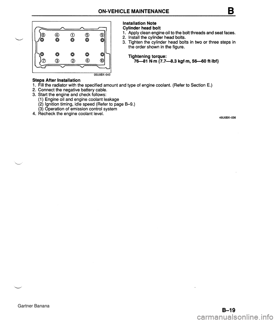
ON-VEHICLE MAINTENANCE B Installation Note Cylinder head bolt I I 05UOBX-043 Stem After Installation Apply clean engine oil to the bolt threads and seat faces. Install the cylinder head bolts. Tighten the cylinder head bolts in two or three steps in the order shown in the figure. Tightening torque: 76-81 N.m (7.7-8.3 kgf-m, 56-60 ft4bf) 1. pill the radiator with the specified amount and type of engine coolant. (Refer to Section E.) 2. Connect the negative battery cable. 3. Start the engine and check follows: (1) Engine oil and engine coolant leakage (2) Ignition timing, idle speed (Refer to page B-9.) (3) Operation of emission control system 4. Recheck the engine coolant level. Gartner Banana
Page 59 of 1708

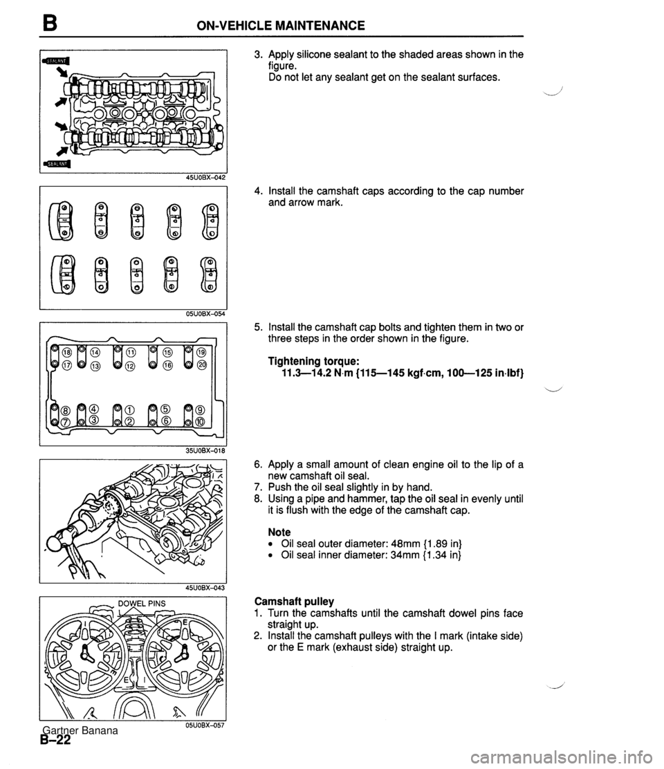
B ON-VEHICLE MAINTENANCE I - DOWEL PINS I 3. Apply silicone sealant to the shaded areas shown in the figure. Do not let any sealant get on the sealant surfaces. 4. Install the camshaft caps according to the cap number and arrow mark. 5. Install the camshaft cap bolts and tighten them in two or three steps in the order shown in the figure. Tightening torque: 11.3-1 4.2 N.m (115--145 kgf.cm, 100-125 in-lbf} ii 6. Apply a small amount of clean engine oil to the lip of a new camshaft oil seal. 7. Push the oil seal slightly in by hand. 8. Using a pipe and hammer, tap the oil seal in evenly until it is flush with the edge of the camshaft cap. Note Oil seal outer diameter: 48mm {I .89 in) Oil seal inner diameter: 34mm {I .34 in} Camshaft pulley 1. Turn the camshafts until the camshaft dowel pins face straight up. 2. Install the camshaft pulleys with the I mark (intake side) or the E mark (exhaust side) straight up. Gartner Banana
Page 60 of 1708

ON-VEHICLE MAINTENANCE B I I 35UOBX-020 Stem After Installation 3. Install the camshaft pulley lock bolts. 4. Hold the camshaft with a wrench at the cast hexagon. 5. Tighten the camshaft pulley lock bolt. Tightening torque: 50-60 Nm C5.0-6.2 kgfm, 3744 ft4bf) 1. pill the radiator with the specified amount and type of engine coolant. (Refer 2. Connect the negative battery cable. 3. Start the engine and check follows: (1) Engine coolant leakage (2) Ignition timing (Refer to page 59.) 4. Recheck the engine coolant levels. to section E.) Gartner Banana
Page 89 of 1708

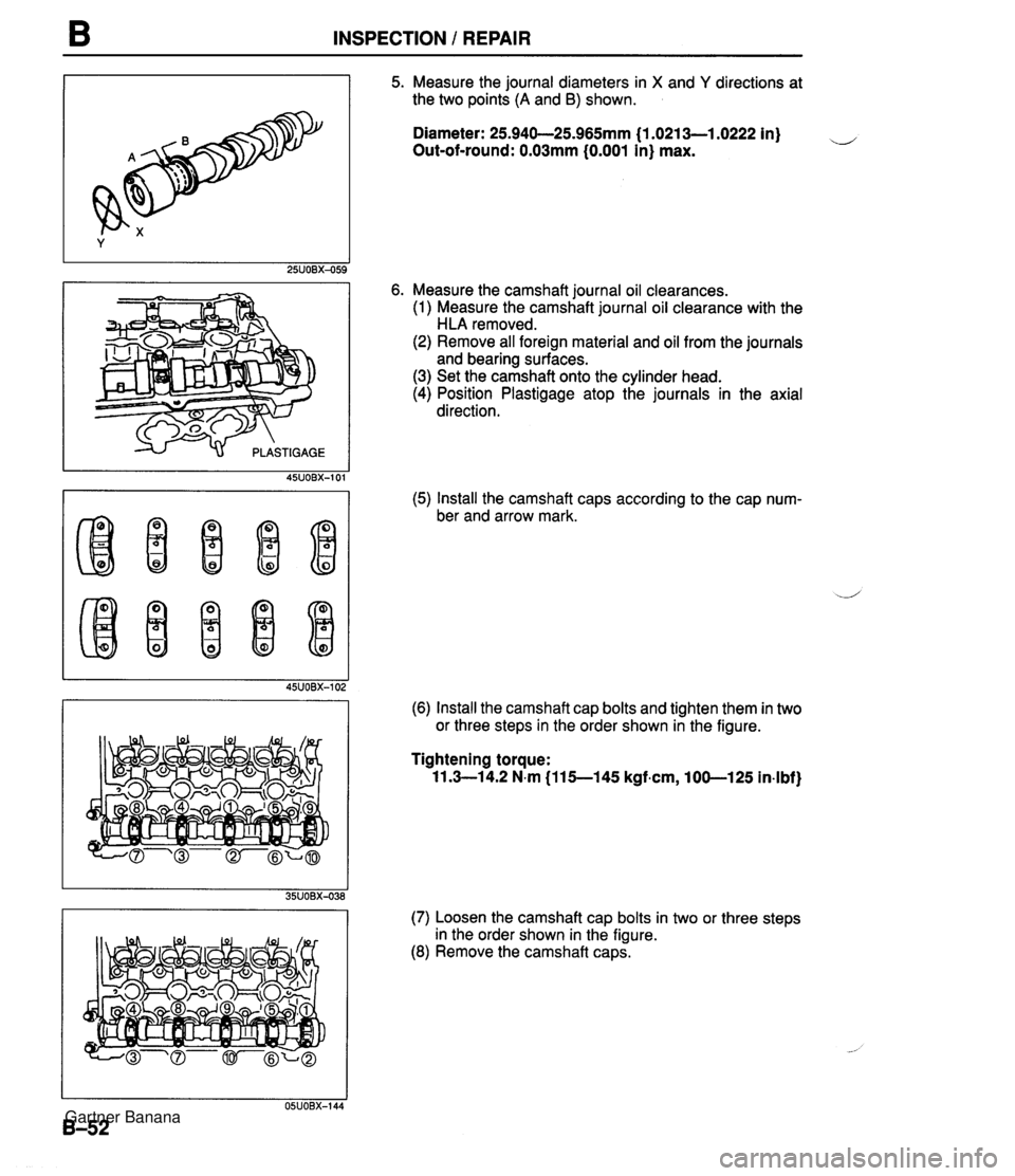
B INSPECTION / REPAIR 5. Measure the journal diameters in X and Y directions at the two points (A and B) shown. Diameter: 25.940-25.965mm {I .0213-1.0222 in) u Out-of-round: 0.03mm (0.001 in) max. 6. Measure the camshaft journal oil clearances. (1) Measure the camshaft journal oil clearance with the HLA removed. (2) Remove all foreign material and oil from the journals and bearing surfaces. (3) Set the camshaft onto the cylinder head. (4) Position Plastigage atop the journals in the axial direction. (5) Install the camshaft caps according to the cap num- ber and arrow mark. (6) Install the camshaft cap bolts and tighten them in two or three steps in the order shown in the figure. Tightening torque: 11.3-14.2 N.m (115-145 kgfmn, 100-125 in-lbf) (7) Loosen the camshaft cap bolts in two or three steps in the order shown in the figure. (8) Remove the camshaft caps. Gartner Banana
Page 97 of 1708

ASSEMBLY 1. Do not reuse gaskets or oil seals. 2. Clean all parts before reinstallation. 3. Apply new engine oil to all sliding and rotating parts. 4. Replace plain bearings if they are peeled, burned, or otherwise damaged. 5. Tighten all bolts and nuts to the specified torques. CYLINDER BLOCK (INTERNAL PARTS) Torque Specifications CYLINDER WALLS I#- WASHER, NEW JOURNALS AND BEARINGS NEW Connecting Rod and Piston Assembly 1. Install one piston pin clip into the clip groove in the pis- ton. 2. Assemble the piston and the connecting rod. 3. Apply clean engine oil to the piston pin. 4. Install the piston pin from the side opposite the clip. 5. Tap the piston pin in with the SST until the pin contacts the clip. . , If the pin cannot be installed easily, replace the connect- ing rod. 6. Install the second clip into the clip groove in the piston. Gartner Banana
Page 98 of 1708

ASSEMBLY B SPACER TANG UPPER RAIL ...-.. OIL RlNG SPACER ENDS LOWER RAlL PISTON OIL RlNG UPPER RAIL TOP RING OIL RING + PISTOI PIN OIL RING. SECOND LOWER RAIL RING 7. Check the oscillation torque of the connecting rod. If the large end does not drop by its own weight, replace the piston and/or piston pin. Piston Ring 1. Install the three-piece oil rings on the pistons. (1) Apply clean engine oil to the oil ring spacer and rails. (2) lnstall the oil ring spacer with the ends upward. Note The upper and lower rails are the same. They can be installed with either face upward (3) Install the upper and lower rails. 2. Verify that the spacer tang separates the rails, and that the rails turn smoothly in both directions. 3. lnstall the rings with the R marks upward. 4. Using a piston ring expander, install the second ring with the scraper face downward. 5. Using a piston ring expander, install the top ring. 6. Apply clean engine oil to the top and second piston rings. 7. Position the end gaps of the rings as shown in the figure. Gartner Banana
Page 99 of 1708

B ASSEMBLY I PLASTIGAGE I Oil Jet lnstall the oil jets. Tightening torque: 12-1 7 N.m (1.2-1.8 kgf.m, 9-1 3 ft4bf) Crankshaft 1. Before installing the crankshaft, inspect the main bear- ing oil clearances as follows. Oil clearance inspection (1) Remove all foreign material and oil from the journals and bearings. (2) lnstall the grooved upper main bearings in the cylin- der block. (3) lnstall the thrust bearings with the oil groove facing the crankshaft. (4) Set the crankshaft in the cylinder block. (5) Position plastigage atop the journals in the axial direction. (6) Do not rotate the crankshaft when measuring the oil clearances. Install the lower main bearings and the main bearing caps according to the cap number and + mark. Tighten the main bearing cap bolts in two or three steps in the order shown in the figure. Tightening torque: 54--58 N-m I5.5--6.0 kgf.m, 40-43 ft4bf) (9) Remove the main bearing caps, and measure the plastigage at each journal at the widest point for the smallest clearance, and at the narrowest point for the largest clearance. (10) If the oil clearance exceeds specification, grind the crankshaft and use undersize main bearings. (Refer to page B-57.) , d' Oil clearance: 0.018-0.036mm (0.0008--0.0014 in) Maximum: 0.lOmm (0.004 in) Gartner Banana