Compression MAZDA MX-5 1994 Owner's Manual
[x] Cancel search | Manufacturer: MAZDA, Model Year: 1994, Model line: MX-5, Model: MAZDA MX-5 1994Pages: 1708, PDF Size: 82.34 MB
Page 211 of 1708
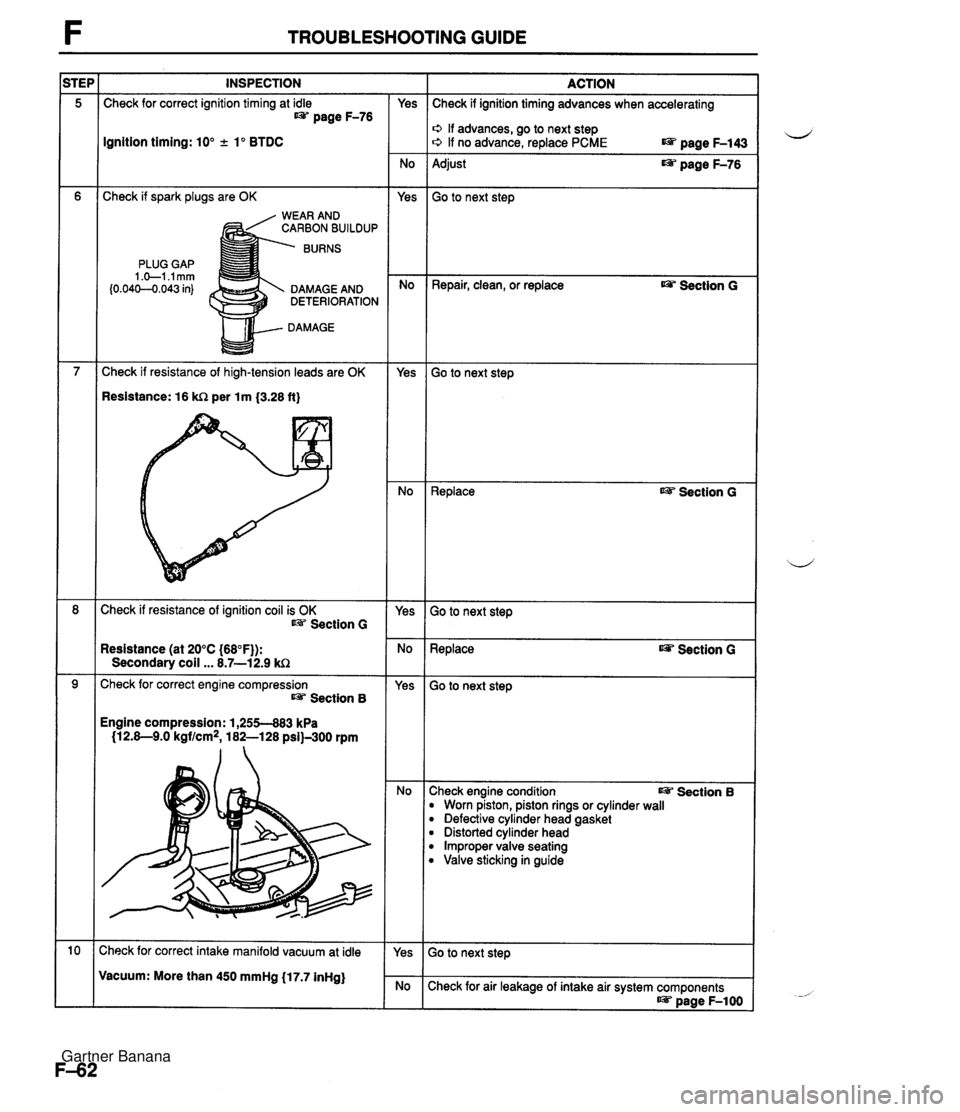
TROUBLESHOOTING GUIDE INSPECTION Check for correct ignition timing at idle t@= page F-76 Ignition timing: 10" +. lo BTDC Check if spark plugs are OK WEAR AND CARBON BUILDUP BURNS PLUG GAP 1 .+I .I mm (0.04C-O.043 in) DAMAGE AND DETERIORATION DAMAGE Check if resistance of high-tension leads are OK Resistance: 16 kR per lm {3.28 ft} Check if resistance of ignition coil is OK Section G Resistance (at 20°C {68"F)): Secondary coil ... 8.7-12.9 kC2 Check for correct engine compression Section 8 Engine compression: 1,255-883 kPa (12.8-9.0 kgf/cm2, 182-128 psi)-300 rpm :heck for correct intake manifold vacuum at idle Vacuum: More than 450 mmHg (17.7 inHg) - Yes - No Yes - No - Yes - No - Yes - No - Yes - No - Yes ACTION Check if ignition timing advances when accelerating o If advances, go to next step o If no advance, replace PCME page F-143 Adjust page F-76 Go to next step Repair, clean, or replace Ojp Section G Go to next step ~eplace as? Section G Go to next step Replace Section G - -- Go to next step :heck engine condition I@= Section B B Worn piston, piston rings or cylinder wall B Defective cylinder head gasket B Distorted cylinder head B Improper valve seating B Valve sticking in guide Check for air leakage of intake air system components as? page F-1 00 Gartner Banana
Page 217 of 1708

TROUBLESHOOTING GUIDE INSPECTION Check for correct fuel line pressure at idle Section B ACTION Go to next step - Yes High compression Check engine condition Carbon deposits Engine compression: 1,255-883 kPa 112.8-9.0 kgf/cm2, 182-128 psi)-300 rpm Section B Check for correct fuel line pressure at idle page F-110 Yes - No Check if fuel line pressure decreases when accelerating quickly Fuel line pressure: 265-314 kPa (2.7-43.2 kgf/cm2, 38-46 psi) (Vacuum hose to pressure regulator discon- nected) 0 If decreases, check for clogging between fuel pump and pressure regulator 0 If no decrease, go to next step Low pressure Check fuel line pressure while pinching fuel return hose 0 If fuel line pressure quickly increases, check pressure regulator page F-118 0 If fuel line pressure gradually increases, check for clog- ging between fuel pump and pressure regulator If not clogged, check fuel pump maximum pressure w page F-115 INSTALL CLAPS Check for correct ignition timing at idle IJ&T page F-76 Yes Check if ignition timing advances when accelerating o If advances, go to next step o If no advance, replace PCME LW page F-143 Ignition timing: 10" + lo BTDC No - Yes Adjust page F-76 Check for EGR system malfunction page F-124 Repair or replace Go to next step Go to next step Check if cooling system is OK Section E Yes No - Yes Repair or replace Thermostat Electric cooling fan Radiator ~3 Section E Section B Section E Try known good PCME and check if condition im- proves IJ&T page F-144 Replace PCME page F-143 Change fuel to another brand or use higher octane fuel Gartner Banana
Page 539 of 1708
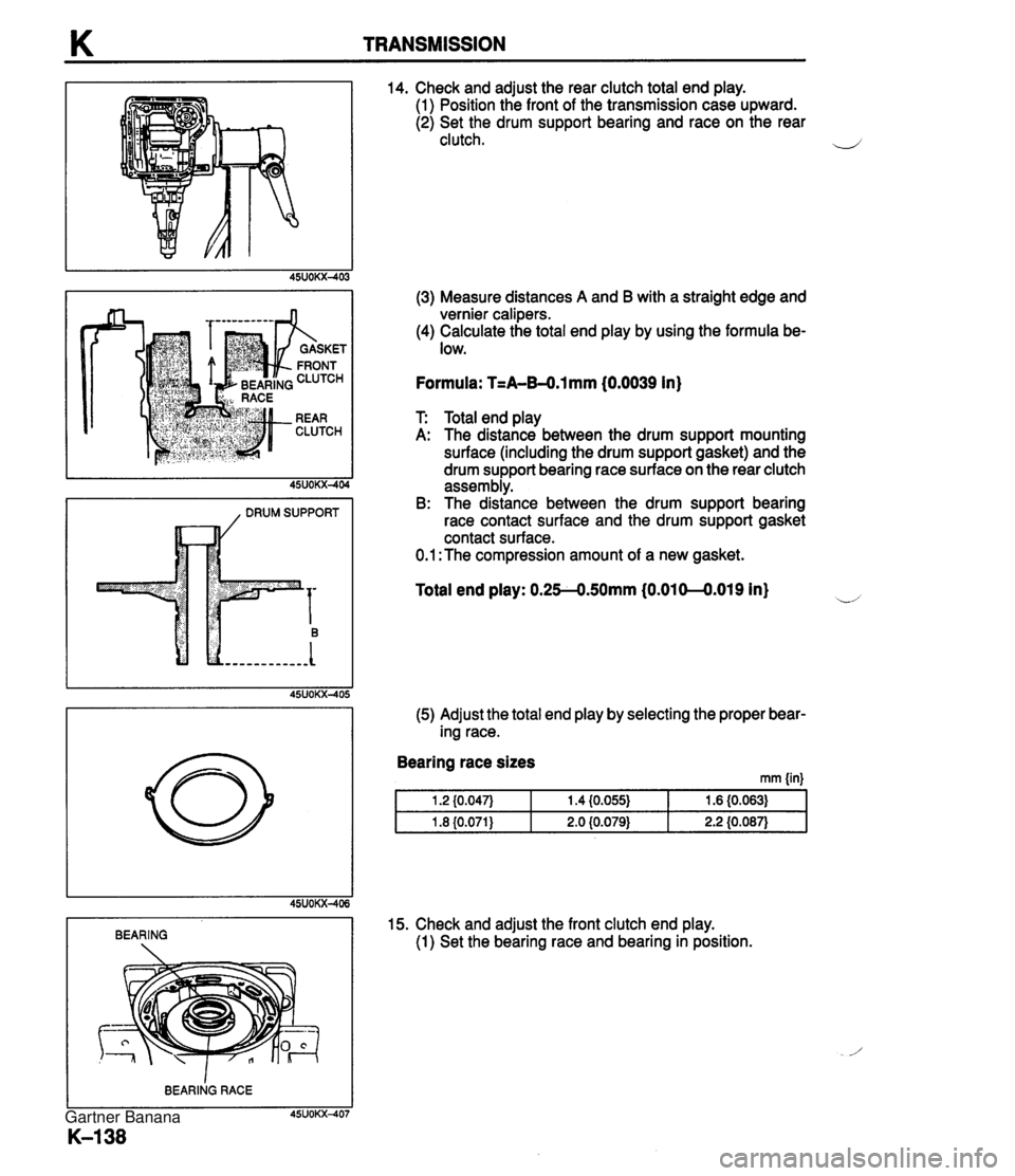
K TRANSMISSION I , DRUM SUPPORT I 14. Check and adjust the rear clutch total end play. (1) Position the front of the transmission case upward. (2) Set the drum support bearing and race on the rear clutch. (3) Measure distances A and B with a straight edge and vernier calipers. (4) Calculate the total end play by using the formula be- low. Formula: T=A-B4.l mm (0.0039 in) T Total end play A: The distance between the drum support mounting surface (including the drum support gasket) and the drum support bearing race surface on the rear clutch assembly. B: The distance between the drum support bearing race contact surface and the drum support gasket contact surface. 0.1 :The compression amount of a new gasket. Total end play: 0.254.50mm (0.010-0.019 in) (5) Adjust the total end play by selecting the proper bear- ing race. I BEARING Bearing race sizes mm {in) 15. Check and adjust the front clutch end play. (1) Set the bearing race and bearing in position. Gartner Banana
Page 540 of 1708
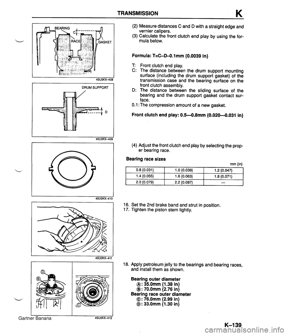
TRANSMISSION K DRUM SUPPORT (2) Measure distances C and D with a straight edge and vernier calipers. (3) Calculate the front clutch end play by using the for- mula below. Formula: T=C-04.1 mm {0.0039 In) T Front clutch end play. C: The distance between the drum support mounting surface (including the drum support gasket) of the transmission case and the bearing surface on the front clutch assembly. D: The distance between the sliding surface of the bearing and the drum support gasket contact sur- face. 0.1 :The compression amount of a new gasket. (4) Adjust the front clutch end play by selecting the prop- er bearing race. Front clutch end play: 0.5--0.8mm (0.020--0.031 in) Bearing race sizes rnm (in) 16. Set the 2nd brake band and strut in position. 17. Tighten the piston stem lightly. 18. Apply petroleum jelly to the bearings and bearing races, and install them as shown. Bearing outer diameter 0: 35.0mm (1.38 in) @: 70.0mm (2.76 in) Bearing race outer diameter 0: 76.0mm (2.99 in) 0: 33.0mm (1.30 in) Gartner Banana
Page 541 of 1708
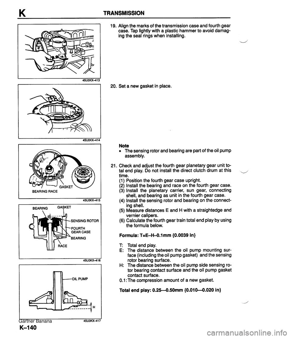
K TRANSMISSION I BEARING I SENSING ROTOR FOURTH GEAR CASE BEARING 19. Align the marks of the transmission case and fourth gear case. Tap lightly with a plastic hammer to avoid damag- ing the seal rings when installing. 20. Set a new gasket in place. Note The sensing rotor and bearing are part of the oil pump assembly. 21. Check and adjust the fourth gear planetary gear unit to- tal end play. Do not install the direct clutch drum at this .-, time. (1) Position the fourth gear case upright. (2) Install the bearing and race on the fourth gear case. (3) Install the planetary carrier, sun gear, connecting shell, and bearing as unit in the fourth gear case. (4) Install the sensing rotor and bearing on the connect- ing shell. (5) Measure distances E and H with a straightedge and vernier calipers. (6) Calculate the fourth gear train total end play by using the formula below. Formula: T=E-H-O.1 mm (0.0039 in) T Total end play. E: The distance between the oil pump mounting sur- face (including the oil pump gasket) and the sensing rotor bearing surface. H: The distance between the oil pump side sensing ro- tor bearing contact surface and the oil pump gasket contact surface. 0.1 :The compression amount of a new gasket. Total end play: 0.25-0.50mm (0.01 0-0.020 in} Gartner Banana
Page 542 of 1708
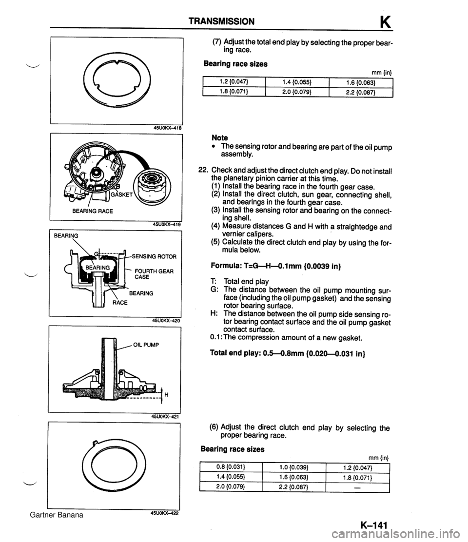
TRANSMISSION K BEARING RACE 45UOKX-419 ROTOR I GEAR (7) Adjust the total end play by selecting the proper bear- ing race. Bearing race sizes mm linl Note The sensing rotor and bearing are part of the oil pump assembly. Check and adjust the direct clutch end play. Do not install the planetary pinion carrier at this time. (1) Install the bearing race in the fourth gear case. (2) Install the direct clutch, sun gear, connecting shell, and bearings in the fourth gear case. (3) Install the sensing rotor and bearing on the connect- ing shell. (4) Measure distances G and H with a straightedge and vernier calipers. (5) Calculate the direct clutch end play by using the for- mula below. Formula: T=G-H4.l mm (0.0039 in) T: Total end play G: The distance between the oil pump mounting sur- face (including the oil pump gasket) and the sensing rotor bearing surface. H: The distance between the oil pump side sensing ro- tor bearing contact surface and the oil pump gasket contact surface. 0.1 :The compression amount of a new gasket. Total end play: 0.M.8mm (0.020--0.031 in) (6) Adjust the direct clutch end play by selecting the proper bearing race. Bearing race sizes rnm {in} Gartner Banana
Page 1110 of 1708

TD TECHNICAL DATA A. MEASUREMENTS I Item I Measurements I B. ENGINE Overall length mm {in) Overall width mm (in) Overall height mm {in) Wheelbase mm {in) 3,948 (1 55.4) 1,676 i65.9) 1,224 I48.2) 2,266 I89.2) 1,410 (55.5) 1,428 (56.2) Tread - ltem Tvoe u Front mm (in) Rear mm {in) BP DOHC Gasoline. 4-cvcle . In-line, 4-cylinders Pentroof DOHC, belt-driven 16 valves 83.0 x 85.0 {3.27 x 3.35) 1,840 (1,840, 11 2) 9.0 1,255 {I 2.8, 1823-300 883 (9.0, 1281-300 196 {2.0, 28) s. Cylinder arrangement and number Combustion chamber Valve system Bore x Stroke mm {in] Total piston displacement ml {cc, cu in) Compression ratio Valve timing Compression pressure kPa (kgflcm2. psil-r~m I Valve and valve auide I Standard Minimum Maximum difference between each cvlinder - - IN openz (BTDCO) Close (ABDCO) Open (BBDCO) EX close (ATDC") Valve clearance mm {in) Cylinder head 5 48 56 14 IN 133.8-1 34.0 i5.268-5.275) 0.1 0 {0.004) max. 0.10 {0.004) max. 0.02G0.066 {0.0010-0,0025) 0.18 {0.0071) Height mm (in) Distortion mm {in) Grinding mm {in) - 0: Maintenance-free Cylinder head-to-HLA clearance mm (in} Valve head diameter mm Iin) Valve head margin thickness mm {in} Valve face angle I Valve seat 1 u Standard Maximum Valve length mm {in) EX IN EX IN EX IN EX Standard Minimum Standard Minimum IN EX IN EX 5.99--6.03 iO.2359--0.2374) 0.005--0.060 (0.0002-0.0023) 0.01 b0.065 (0.0004-0,0025) 0.20 {0.008} 18.3-1 8.9 {0.7214.744) 18.3-1 8.9 (0.721-0.744) Guide inner diameter mm (in) 0: Maintenance-free 32.9-33.1 {I .296--1.303) 27.85-28.15 {I .097-1 .I 08) 0.9 {0.035) 1 .O (0.039) 45" 45" 101.89 {4.0114} 100.39 {3.9524) 101.99 (4.0153) 100.49 (3,9563) 5.970-5.985 {0.2351-0.2356) 5.96G5.980 l0.2349-0.2354) Valve stem diameter mm {in) Valve stem-to-guide clearance mm (in) Guide projection (Height "A) mm {in) Seat angle IN EX Maximum IN EX IN 45" EX 45" Gartner Banana