egr MAZDA MX-5 1994 Owner's Guide
[x] Cancel search | Manufacturer: MAZDA, Model Year: 1994, Model line: MX-5, Model: MAZDA MX-5 1994Pages: 1708, PDF Size: 82.34 MB
Page 741 of 1708

WHEEL ALIGNMENT REAR WHEEL ALIGNMENT Specifications (Unladed*) I Item I Specifications I L *' Fuel tank full; radiator coolant and engine oil at specified levels; spare tire, jack, and tools in designated positions. 05Uo~x-01~ *2 Difference between the leff and right must be exeed lo. 3 + 3 i0.12 * 0.12) 0'18' k18' 0'09' 2 09' -1 "08' +. 30' Total toe-in Total toe-in (per side) Camber angle'' LEFT WHEEL - mm {in) degree degree INCREASE I 1 346-355 (1 3.6-1 4.0) Height from center of wheel to fender brim'2 mm Iin) RIGHT WHEEL C INCREASE 356-3135 {14.0-14.4) 366-375 {I 4.4--14.8) 376-385 {I 4.8-1 5.2) 386--395 {I 5.2-1 5.6) LEFT WHEEL -C -0°54' r 30' -0'43' 2 30' -0°35' r 30' -0'30' +. 30' Toe-in Toe-in is adjusted by turning the front and/or rear adjust- ing cam bolts at the lower arm. Caution Adjust the toe-in before adjusting the camber. 1. Loosen the front and/or rear cam nuts. 2. Turn the front and/or rear adjusting cam bolts to provide the correct toe-in. I Counter- Counter- Decrease Clockwise Clockwise clockwise clockwise Toe-in Note Turning the front cam one graduation changes the toe-in about 2.8mm (0.11 in} and the camber about 15'. Turning the rear cam one graduation changes the toe-in about 2.8mm I0.11 in} and the camber about 6'. 3. 'Adjust the camber. Left wheel Camber Camber is adjusted by turning the front and rear cams at the lower arm. Right wheel Caution Adjust the camber after adjusting the toe-in. Front cam I Rear cam I Front cam I Rear cam 1. Loosen the front and rear cam nuts. 2. Turn the front and rear adjusting cam bolts the same amount in the opposite direction to provide the correct camber angle. Gartner Banana
Page 803 of 1708
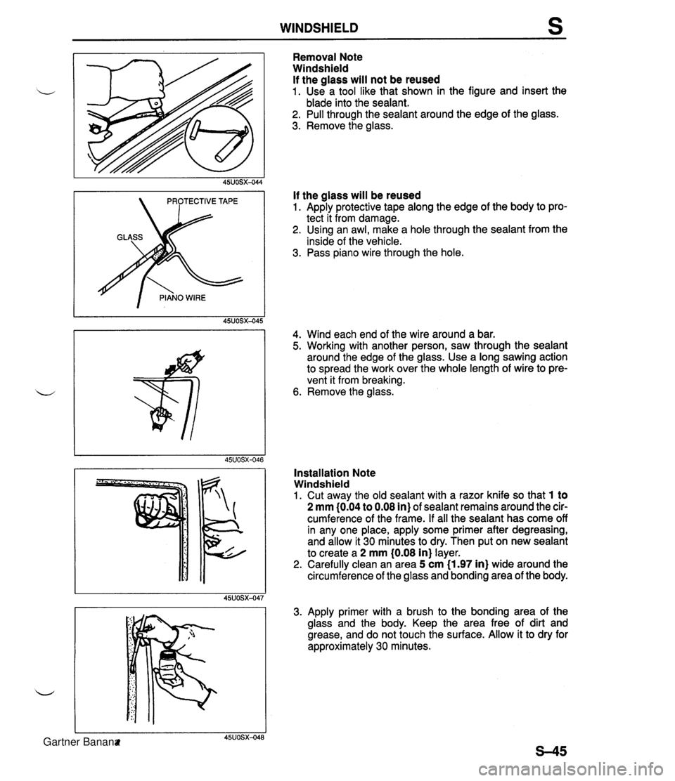
WINDSHIELD Removal Note Windshield If the glass will not be reused 1. Use a tool like that shown in the figure and insert the blade into the sealant. 2. Pull through the sealant around the edge of the glass. 3. Remove the glass. If the glass will be reused 1. Apply protective tape along the edge of the body to pro- tect it from damage. 2. Using an awl, make a hole through the sealant from the inside of the vehicle. 3. Pass piano wire through the hole. 4. Wind each end of the wire around a bar. 5. Working with another person, saw through the sealant around the edge of the glass. Use a long sawing action to spread the work over the whole length of wire to pre- vent it from breaking. 6. Remove the glass. Installation Note Windshield 1. Cut away the old sealant with a razor knife so that 1 to 2 mm (0.04 to 0.08 in) of sealant remains around the cir- cumference of the frame. If all the sealant has come off in any one place, apply some primer after degreasing, and allow it 30 minutes to dry. Then put on new sealant to create a 2 mm (0.08 in} layer. 2. Carefully clean an area 5 cm (1.97 in) wide around the circumference of the glass and bonding area of the body. 3. Apply primer with a brush to the bonding area of the glass and the body. Keep the area free of dirt and grease, and do not touch the surface. Allow it to dry for approximately 30 minutes. Gartner Banana
Page 822 of 1708

s SEAT BELT SEAT BELT lnspection ELF? 1. Verify that the belt can be pulled out smoothly, and that d it moves smoothly when worn. 2. Verify that the retractor locks when the belt is quickly pulled. 3. Remove the retractor. 4. Hold the retractor as it would be installed. 5. Slowly incline the retractor while pulling out the belt. 6. Verify that the retractor locks at approximately 30 degrees inclination. Webbing Inspect the webbing for scars, tears, and wear and for deformation of the fittings. BUCKLE SWITCH lnspection 1. Disconnect the seat belt buckle switch connector. 2. Check for continuity between the switch terminals. I Unbuckled I Yes I Seat belt Buckled 3. If continuity is not as specified, replace the switch. Continuity No d Gartner Banana
Page 945 of 1708

T CRUISE CONTROL SYSTEM SELF-DIAGNOSTIC INSPECTION Self-diagnostic Function The Self-diagnostic function integrated within the cruise control unit diagnoses the condition of the cruise control system. 4 Conditionfoperation codes are indicated by flashing of the test light connected to the control unit. (Refer to condition code numbers on pages T-101, 102.) This operation continues until canceled. 45UOTX-201 Principle of Code Cycle Condition and operation codes are determined by flashing of the test light connected to the control unit as shown below. 03UOTX-140 1. Code cycle break The time between conditionloperation code cycles is 4.0 seconds (the time the light is off). CONDITION/OPERATION * ODE CYCLE BREAK - - 4.0 sec 2. Second digit of conditionloperation code (ones position) The digit in the ones position of the conditionloperation code represents the number of times the light is on 014 second during one cycle. - CONDITION/OPERATION 1 CYCLE CODE CODE: 03 ON OFF .. ... 4.0 4.0 4.0 SeC sec sec 3. First digit of conditionloperation code (tens position) The digit in the tens position of the conditionloperation code represents the number of times the light is on 1.2 seconds during one cycle. The light remains off for 1.6 seconds between the long and short flashes. MALFUNCTION 1 CYCLE MALFUNCTION CODE CODE: 22 FIRST DlGlT SECOND DIGIT 45UOTX-204 - - 1.2- 0.4. 1.6 - -- - C CYCLE BREAK * C 4.0 sec sec Gartner Banana
Page 1002 of 1708

SRS AIR BAG SYSTEM T COMPONENT DESCRIPTION Component Air bag module Function Air bag system warning light Deploys air bag when current flows to integrated igniter Light illuminates or flashes if malfunction occurs in air bag system I EE with S-sensor, completes Circuit Clock spring I Ensures uninterrupted electrical connec- tion to air bag module while allowing turning of steering wheel Activated(closed) when crash impact de- Crash sensor Diagnostic module to infktor Activated(closed) when crash impact de- S-sensor 1 Monitors com~onents and harnesses in tected Acting with D-sensor, completes circuit to inflator Remark Located in instrument cluster Location: Driver side . . . . . . . . in steering wheel hub Passenger side . . . above the glove compartment Part of combination switch Located in front part of vehicle(left, right, and center) Located behind heater unit in passenger compartment Contains back-up battery air bag system Indicates system malfunction by flashing or illuminating air bag system warning light If warning light is bunt, sounds warning buzzer Detects short circuit between air bag module and ground or crash sensor rnal- function and melts system fuse to pre- vent unintended air bag deployment Gartner Banana
Page 1122 of 1708

TECHNICAL DATA R. SUSPENSION Front sus~ension I i/ Differential - . - ~- Coil springs MT I AT Shock absorbers "TORSEN" LSD TY ~a Cylindrical double-acting, low-pressure gas charged Standard Stabilizer Double-wishbone Torsion bar Wire diameter mm {in) Coil inner diameter mm {in} Rear suspension Tv~e I Double-wishbone TY pe Diameter mm {in) 20.0 (0.79) I Identification color 11 .O {0.43} 83.0 f3.27) . . Free length mm {in) Coil number 19.0 {0.75} . . 292.5 (1 1.52) 1 302.0 {I 1.89) 6.32 I - . I1 . ,I . , I Shock absorbers Cylindrical double-acting, low-pressure gas charged White I I Identification color I Yellow I Green I Blue Torsion bar 12.0 (0.471 1 11 .O 10.43) .a Stabilizer TYPe Diameter mm {in) Coil springs Wheel alignment I Front wheel alignment (Unladen'') I I - Caster angle*3 King pin angle I tun'aoen 'I 1 Camber angle'2 -0°43' 2 30' I I - Wire diameter mm {in) Coil inner diameter mm {in) Free length mm {in} Coil number Maximum steering angle 4O26' -c 45' 11 "20' Rear wheel alignment ,, l-l_A_-*i, *1 Fuel tank full; radiator coolant and engine oil at specified level, and spare tire, jack, and tools in designated position. *2 Difference between left and right must not exceed lo. *3 Difference between left and right must not exceed 1'30'. 10.1 (0.40) Inner Outer 10.2 I0.40) mm (in) Camber ana~e*~ J 3 + 3 10.12 r 0.12) 0°18' 2 18' -. - 3 r 3 {0.12 2 0.12) 0'24' 2 45' 37O23' 2 2" 32O32' 2 2" Total toe-in 83.0 i3.27) U' mm {in} degree 348.5 113.72) Total toe-in 356.5 {I 4.04) dearee 7.68 0'18' & 18' 7.96 Gartner Banana
Page 1125 of 1708
SPECIAL TOOLS GENERAL INFORMATION The letters A and B in the priority column indicate the degree of importance of each tool. A . . . . . Indispensable u The tools ranked A in this list are indispensable for performing operations satisfactorily, easily, safely, and efficiently. It is, therefore, advisable that all service shops have these tools. B . . . . . Selective The tools ranked B are not as necessary as tools ranked A, but all service shops should have them to perform repairs more easily and efficiently. 25USTX-001 Gartner Banana
Page 1260 of 1708

GENERAL SERVICE INFORMATION VEHICLE DIMENSIONS d Measurement I I Overall height mm (in) I Overall length mm (in) Overall width mm (in) 3,948 (155.4) 1,676 (65.9) WHEEL ALIGNMENT Front wheel alignment (Unloaded*) 2,266 (89.2) 1,410 (55.5) 1,428 (56.2) Wheelbase mm (in) Rear wheel alignment (Unloaded*) Tread Total toe-in Front mrn (in) Rear mm (in) mm (in) degree Camber angle I 0'24' f 30' 3 + 3 (0.12 f 0.12) 0°18' + 18' Maximum steering angle Inner Outer I 37'23' f 2O 32O32' f 2O Caster angle * Fuel tank full; radiator coolant and engine oil at specified levels; and spare tire, jack, and tools in designated positions. 4O4Y f 45' 1 1°20' 3 * 3 (0.12 f 0.12) 0'18' + 18' King pin angle Camber angle Total toe-in -0'43' f 30' mm (in) degree Gartner Banana
Page 1331 of 1708
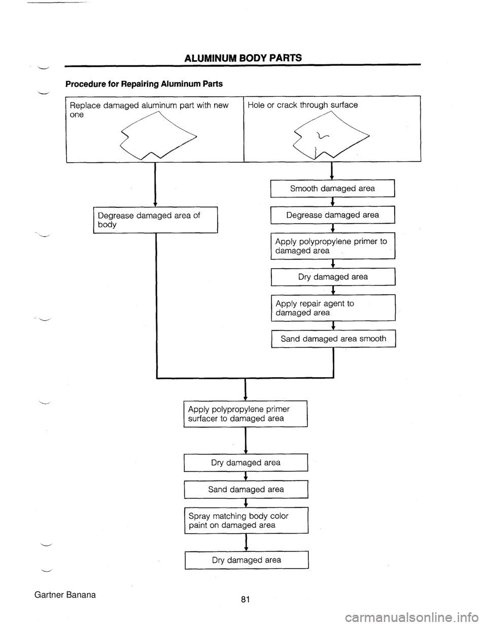
ALUMINUM BODY PARTS V Procedure for Repairing Aluminum Parts Apply polypropylene primer surfacer to damaged area Replace damaged aluminum part with new one Dry damaged area I Hole or crack through surface + Sand damaged area Spray matching body color paint on damaged area I 0 .;. + Dry damaged area v Degrease damaged area of body Smooth damaged area C Degrease damaged area C Apply polypropylene primer to damaged area C Dry damaged area C Apply repair agent to damaged area C I Sand damaged area smooth r Gartner Banana
Page 1337 of 1708
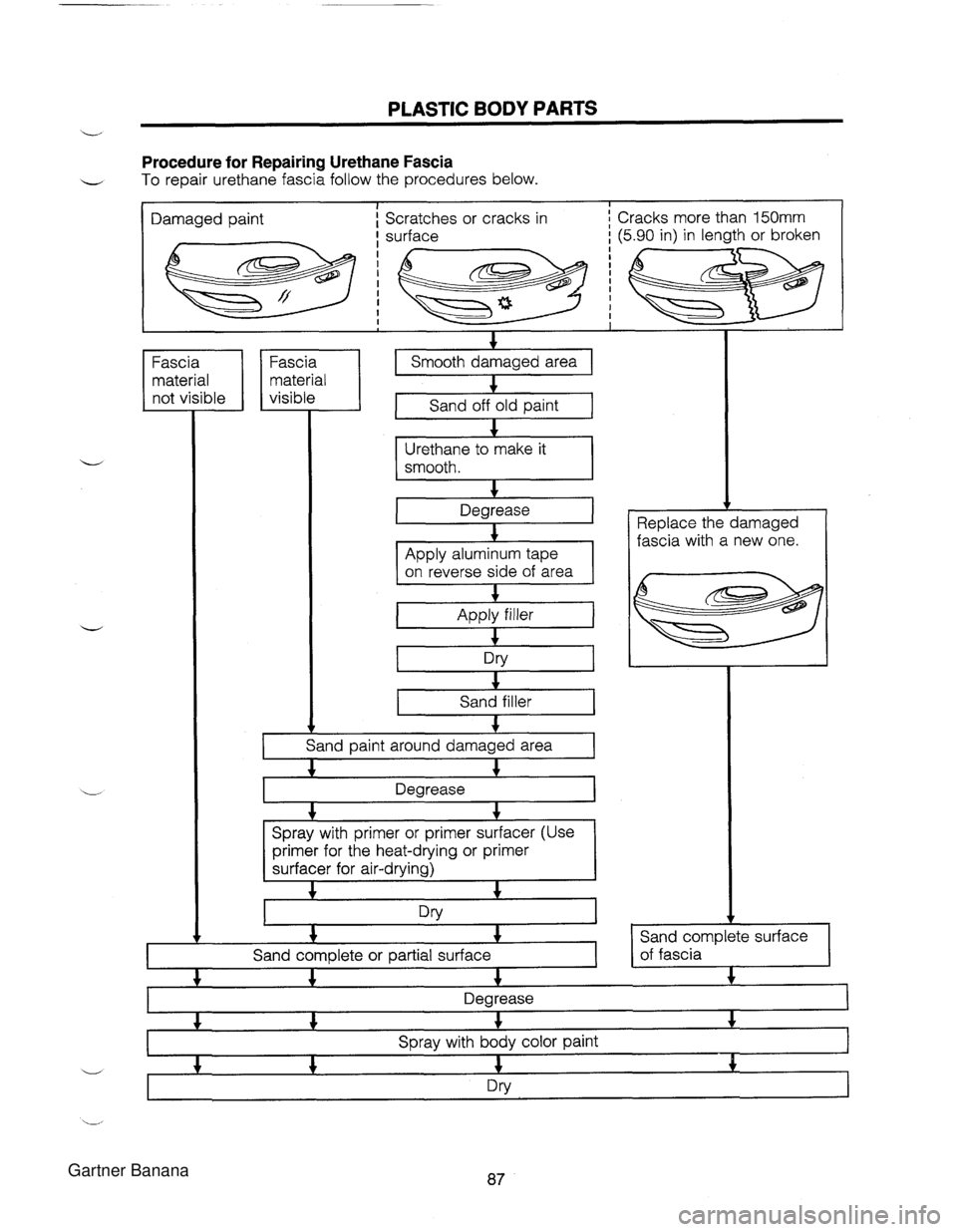
PLASTIC BODY PARTS Procedure for Repairing Urethane Fascia - To repair urethane fascia follow the procedures below. I Damaged paint Scratches or cracks in Fascia material not visible + Smooth damaged area material visible 1 Fa"ia I 1 4 Sand off old paint Urethane to make it Sand filler I hand paint around damaged area I Spray with primer or primer surfacer (Use primer for the heat-drying or primer surfacer for air-drying) Sand complete or partial surface I Replace the damaged fascia with a new one. I I v Sand complete surface of fascia + + + + Degrease 4 4 4 4 Spray with body color paint 4 4 4 4 Dry Gartner Banana