egr MAZDA MX-5 1994 Owner's Manual
[x] Cancel search | Manufacturer: MAZDA, Model Year: 1994, Model line: MX-5, Model: MAZDA MX-5 1994Pages: 1708, PDF Size: 82.34 MB
Page 269 of 1708

FUEL SYSTEM 1. Disconnect the negative battery terminal. 2. Remove the PCV hose. 3. Disconnect the vacuum hose. 4. Disconnect the fuel injector connectors. 5. Remove the fuel distributor and the pressure regulator. 6. Remove the grommets, fuel injectors, and insulators. Inspection Fuel leakage test 1. Firmly affix the fuel injectors to the fuel distributor with wire. 2. Disconnect the fuel injector connectors. 3. Remove the fuel distributor and fuel injectors together with the fuel hoses connected. 4. Connect data link connector terminals FIP and GND with a jumper wire. 5. Turn the ignition switch ON. 6. Tilt the fuel injectors approx. 60 degrees and verify that no fuel leaks from the fuel injector nozzles. 7. If fuel leaks from an fuel injector, replace it. Leakage Specification If there is more than one drop per 2 minutes, replace the fuel injector. d 8. Turn the ignition switch OFF and remove the jumper wire. Gartner Banana
Page 273 of 1708

F EXHAUST GAS RECIRCULATION (EGR) EXHAUST GAS RECIRCULATION (EGR) PREPARATION SST I 49 9200 162 Engine Signal Monitor 49 GO1 8 904 Sheet DESCRIPTION For inspection of EGR For inspection of EGR 49 GO1 8 903 For inspection of Adapter EGR harness / TO AIR CLEANER HOUSING I THROTTLE POSITION ENGINE COOLANT SENSOR SENSOR TEMPERATURE CRANKSHAFT SENSOR POSITION SENSOR EGR SOLENOID VALVE (VACUUM) EGR SOLENOID VALVE (VENT) / PCME I This ~~st~rn~recirculates a small amount of exhaust gas into the intake manifold to reduce the combus- tion temperature, and reduce the NOx emissions. This system consists of the EGR control valve, EGR function sensor, two solenoid valves, powertrain control module (engine) (PCME) and input devices. Gartner Banana
Page 274 of 1708
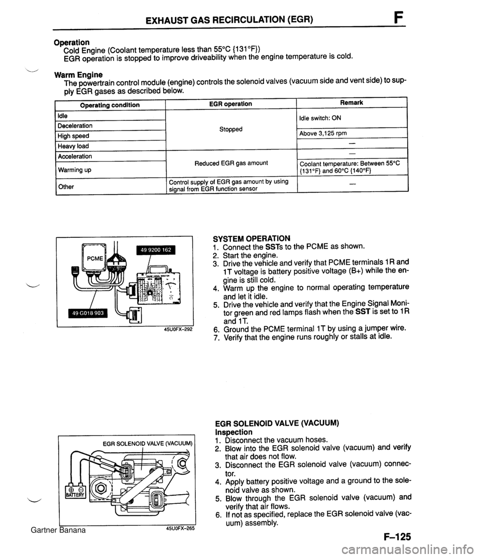
EXHAUST GAS RECIRCULATION (EGR) Operation Cold Engine (Coolant temperature less than 55°C (1 31 OF)) EGR operation is stopped to improve driveability when the engine temperature is cold. u Warm Engine The powertrain control module (engine) controls the solenoid valves (vacuum side and vent side) to sup- ply EGR gases as described below. Remark Operating condition Idle Deceleration High speed Heavy load EGR SOLENOID VALVE (VACUUM) I I EGR operation Acceleration Warming up Other SYSTEM OPERATION 1. Connect the SSTs to the PCME as shown. 2. Start the engine. 3. Drive the vehicle and verify that PCME terminals 1 R and 1 T voltage is battery positive voltage (B+) while the en- gine is still cold. 4. Warm up the engine to normal operating temperature and let it idle. 5. Drive the vehicle and verify that the Engine Signal Moni- tor green and red lamps flash when the SST is set to 1 R and 1 T. 6. Ground the PCME terminal IT by using a jumper wire. 7. Verify that the engine runs roughly or stalls at idle. Stopped EGR SOLENOID VALVE (VACUUM) Inspection 1. Disconnect the vacuum hoses. 2. Blow into the EGR solenoid valve (vacuum) and verify that air does not flow. 3. Disconnect the EGR solenoid valve (vacuum) connec- tor. 4. Apply battery positive voltage and a ground to the sole- noid valve as shown. 5. Blow through the EGR solenoid valve (vacuum) and verify that air flows. 6. If not as specified, replace the EGR solenoid valve (vac- uum) assembly. Idle switch: ON Above 3,125 rpm - Reduced EGR gas amount Control supply of EGR gas amount by using signal from EGR function sensor - Coolant temperature: Between 55OC (1 31 OF) and 60°C {140°F) - Gartner Banana
Page 275 of 1708
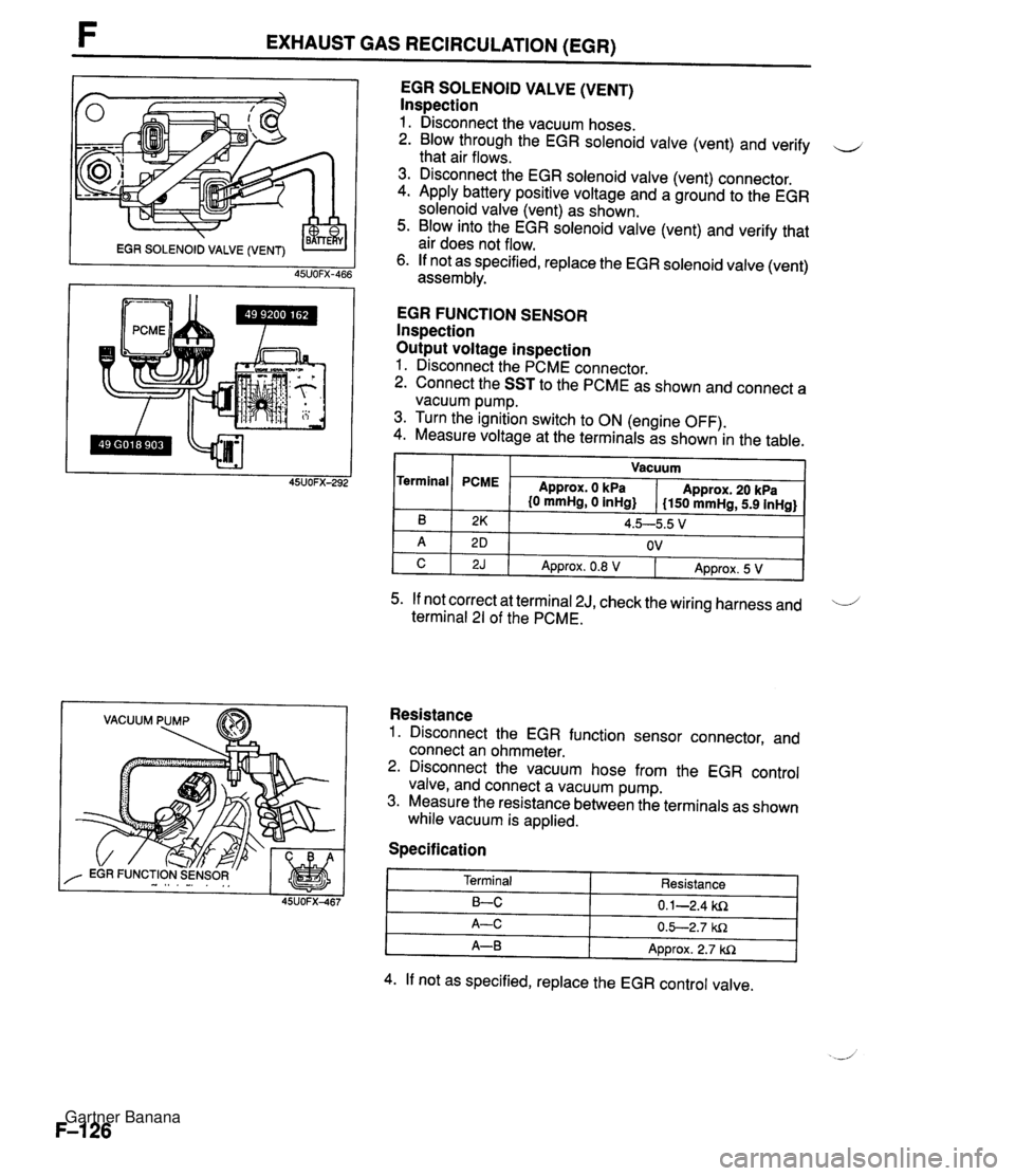
F EXHAUST GAS RECIRCULATION (EGR) VACUUM PUMP EGR SOLENOID VALVE (VENT) lnspection 1. Disconnect the vacuum hoses. 2. Blow through the EGR solenoid valve (vent) and verify u that air flows. 3. Disconnect the EGR solenoid valve (vent) connector. 4. Apply battery positive voltage and a ground to the EGR solenoid valve (vent) as shown. 5. Blow into the EGR solenoid valve (vent) and verify that air does not flow. 6. If not as specified, replace the EGR solenoid valve (vent) assembly. EGR FUNCTION SENSOR lnspection Output voltage inspection 1. Disconnect the PCME connector. 2. Connect the SST to the PCME as shown and connect a vacuum pump. 3. Turn the ignition switch to ON (engine OFF). 4. Measure voltage at the terminals as shown in the table. I I Vacuum I Terminal 5. If not correct at terminal 2J, check the wiring harness and 'i terminal 21 of the PCME. B A C Resistance 1. Disconnect the EGR function sensor connector, and connect an ohmmeter. 2. Disconnect the vacuum hose from the EGR control valve, and connect a vacuum pump. 3. Measure the resistance between the terminals as shown while vacuum is applied. PCME Specification 2K 2 D 2J Approx. 0 kPa {O mmHg, 0 inHg} 4. If not as specified, replace the EGR control valve. Approx. 20 kPa I150 mmHg, 5.9 inHg} 4.5--5.5 V OV Terminal LC A-C A-B Approx. 0.8 V Resistance 0.1-2.4 ki2 0.5-2.7 W1 Approx. 2.7 W1 Approx. 5 V Gartner Banana
Page 276 of 1708

EXHAUST GAS RECIRCULATION (EGR) EGR CONTROL VALVE I EGR CONTROL VALVE Inspection 1. Start the engine and let it idle. 2. Connect a vacuum pump as shown and apply vacuum. 3. Verify that the engine runs roughly or stalls at more than the specified vacuum. Specification: 5.4--12.0 kPa (40-90 mmHg, 1.6-3.5 inHg) 4. If not as specified, replace the EGR control valve. Replacement Plug the water hoses after disconnecting them. 1. Remove the EGR control valve in the sequence shown below. (1 ) EGR hoses (2) Vacuum hose (3) EGR function sensor connector (4) EGR control valve and gasket 2. Install a new gasket, and then install the EGR control valve in the reverse order of removal. Gartner Banana
Page 295 of 1708
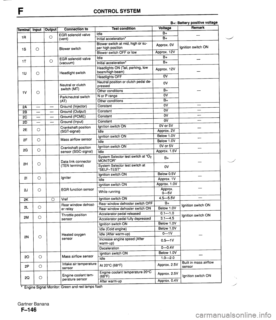
F CONTROL SYSTEM B+: Battery positive voltage Connection to 1 Test condition 1 Voltage I Remark I -- EGR solenoid valvi Idle B+ Blower switch -- EGR solenoid valve (vacuum) :vent) Initial acceleration* Blower switch at mid, high or su- per high position Blower switch OFF or low Headlight switch Neutral or clutch switch (MT) B+ Idle ParWneutral switch (AT) Ground (Injector) Ground (Output) Ground (PCME) Approx. OV - Approx. 12V B+ Headlights ON (Tail, parking, low beamfhigh beam) Headlights OFF Neutral position or clutch pedal de- pressed Other conditions Ground (Input) Crankshaft position (SGT-signal) Ignition switch ON N or fJ range Other conditions Constant Constant Constant -. Mass airflow sensor .. . . EGR function sensor I while running Approx. 0-5v Initial acceleration* Approx, 2V OV ov B+ Constant Ignition switch ON Idle Crankshaft position sensor (SGC-signal) Data link connector (TEN terminal) Igniter I I I Vre f I lanition switch ON 1 4.5-5.9.' 1 - B+ - OV B+ OV OV OV Ignition switch ON Idle - - - OV OV or 5V ADD~OX. 2V - - Ignition switch ON Idle System Selector test switch at "02 MONITOR" System Selector test switch at "SELF-TEST" Ignition switch ON Idle lanition switch ON I . . I I 1 Ignition switch ON I Below 1 .OV I I - - . . Below 1 .OV Below 1 .OV ear window defrost- er relay Throttle position sensor Heated oxygen sensor - OV or 5V Approx. 1.5V B+ ov Below 0.5V Approx. 1 V Approx. 1 .OV - - - " Rear window defroster switch OFF Rear window defroster switch ON Accelerator pedal released Accelerator ~edal fullv de~ressed Mass airflow sensor B+ Below 1 .OV 0.1-1 .o 3.14.5 Intake air temperature sensor Engine coolant tem- perature sensor lgnition switch ON lgnition switch ON Ignition switch ON Idle ireen and red lamps flash At 200C {680Fj Engine coolant temperature 20°C {680F) After warm-up Below 1 .OV 1 .O-2.0 - Approx. 2.5V Approx. 2.5V Approx. 0.4V Built in mass airflow lgnition switch ON Gartner Banana
Page 298 of 1708

CONTROL SYSTEM B+: Battery positive voltage Terminal 1 M 7 1 N 10 1 P 1 Q 1 R 1 S 1 T 1 U Connection to Abnormal voltage Always approx. 1 V Always approx. 7V Possible cause r Vehicle speed sensor malfunction r Short circuit in wiring from vehicle speed sensor to PCME terminal 1 M Vehicle speed sensor - r Vehicle speed senso~malfunction r Open circuit in wiring from vehicle speed sensor to PCME terminal 1 M r Throttle position sensor misadjustment (Refer to page F-154) r Short circuit in wiring from PCME terminal 1 N to throttle position sensor 6 PCME malfunction Always OV Throttle position sensor (idle terminal) Always B+ r Throttle position sensor misadjustment (Refer to page F-154) r Open circuit in wiring from PCME terminal 1 N to throttle position sensor r Open circuit in wiring from throttle position sensor to ground Stoplight switch Always OV (Stoplights OK) r Open circuit in wiring from stoplight switch to PCME terminal 10 r Steering pressure sensor malfunction (Refer to page F-158) Short circuit in wiring from PCME terminal 1 P to steering pressure sensor r PCME malfunction r Steering pressure sensor malfunction (Refer to F-158) r Open circuit in wiring from PCME terminal 1 P to steering pressure sensor Open circuit in wiring from steering pressure sensor to ground r Air conditioning sensor malfunction (Refer to section U) r Short circuit in wiring from PCME terminal 1 Q to air conditioning sensor r Poor connection at PCME connector r PCME malfunction Always OV Steering pressure sensor Always B+ -- Air conditioning sensor Always OV (with blower switch ON) Air conditioning sensor malfunction (Refer to section U) Open circuit in wiring from PCME terminal 1Q to air conditioning sensor Open circuit in wiring from air conditioning sensor to blower switch Always B+ (with blower switch ON) (Blower fan OK) EGR solenoid valve (vent) Always OV r Refer to Code No.29 Troubleshooting (Refer to page F-92) Short circuit in wiring from blower switch to PCME terminal 1 S r Poor connection at PCME connector PCME malfunction Always OV (Blower fan OK) Blower switch Always B+ (Blower fan OK) Open circuit in wiring from blower switch to PCME terminal IS EGR solenoid (vacu- um) Always OV r Refer to Code No.28 Troubleshooting (Refer to paae F-92) Headlight switch Always OV (Headlights OK) r Open or short circuit in wiring from headlight relay to PCME terminal 1 U Gartner Banana
Page 299 of 1708

F CONTROL SYSTEM B+: Battery positive voltage Abnormal voltage Possible cause Terminal 1 v Connection to Neutral switch malfunction (Refer to page F-157) Clutch switch malfunction (Refer to page F-156) Short circuit in wiring from PCME terminal 1 V to neutral or clutch switch Neutral switch malfunction (Refer to page F-157) 0 Clutch switch malfunction (Refer to page F-156) 0 Open circuit in wiring from PCME terminal 1 V to neutral or clutch switch Poor connection at PCME connector 0 ParWneutral switch malfunction (Refer to section K) 0 Short circuit in wiring from parWneutral switch to PCME terminal 1V 0 ParWneutral switch malfunction (Refer to section K) 0 Open circuit in wiring from parWneutral switch to PCME terminal 1 V Always OV Neutral switchlClutch switch (MT) Always B+ Always OV ParWneutral switch (AT) Always B+ Poor contact at ground terminal 0 Open circuit in wiring from PCME to ground Sround More than OV Crankshaft position sensor (SGT-signal) Always OV or approx. 5V Always below 2V or 4V Refer to Code No.03 troubleshooting (Refer to page F-84) Refer to code No.08 Troubleshooting (Refer to page F-86) 0 Short circuit in wiring from PCME terminal 2H to data link connector terminal TEN Mass airflow sensor Always OV Data link connector (Terminal TEN) 0 Open circuit in wiring from PCME terminal 2H data link connector terminal TEN 0 Open circuit in wiring from data link connector terminal GND to around Always B+ Igniter EGR function sensor Always OV Always approx. OV or approx. 5v Refer to Code No.01 troubleshooting (Refer to paae F-83) 0 Refer to Code No.16 Troubleshooting (Refer to page F-89) 0 Short circuit in wiring from PCME terminal 2K tothrottle position sensor, PCME, or mass airflow sensor Poor connection at PCME connector PCME malfunction Vre f Always OV lllumination light ON when rear window defroster switch ON Open or short circuit in wiring from rear window de- froster switch to PCME terminal 2L Always below 1 .ov Rear window defroster switch Open circuit in wiring from ignition switch to rear win- dow defroster switch Rear window defroster switch malfunction (Refer to section T) lllumination light never ON Open circuit in wiring from PCME terminal 2M to throttle position sensor 0 Open circuit in wiring from PCME terminal 2K to throttle position sensor 0 Open circuit in wiring from PCME terminal 20 to throttle position sensor Always constant Throttle position sensor Alwavs above 1V 0 Throttle position sensor misadjustment Refer to Code No.15 troubleshooting (Refer to page F-88) OV after warm-up Heated oxygen sensor Always approx, 1V after warm-up 0 Refer to Code No.17 troubleshooting (Refer to page F-90) Refer to Code No.08 troubleshooting (Refer to page F-86) Mass airflow sensor Always OV or approx. 5V Gartner Banana
Page 412 of 1708
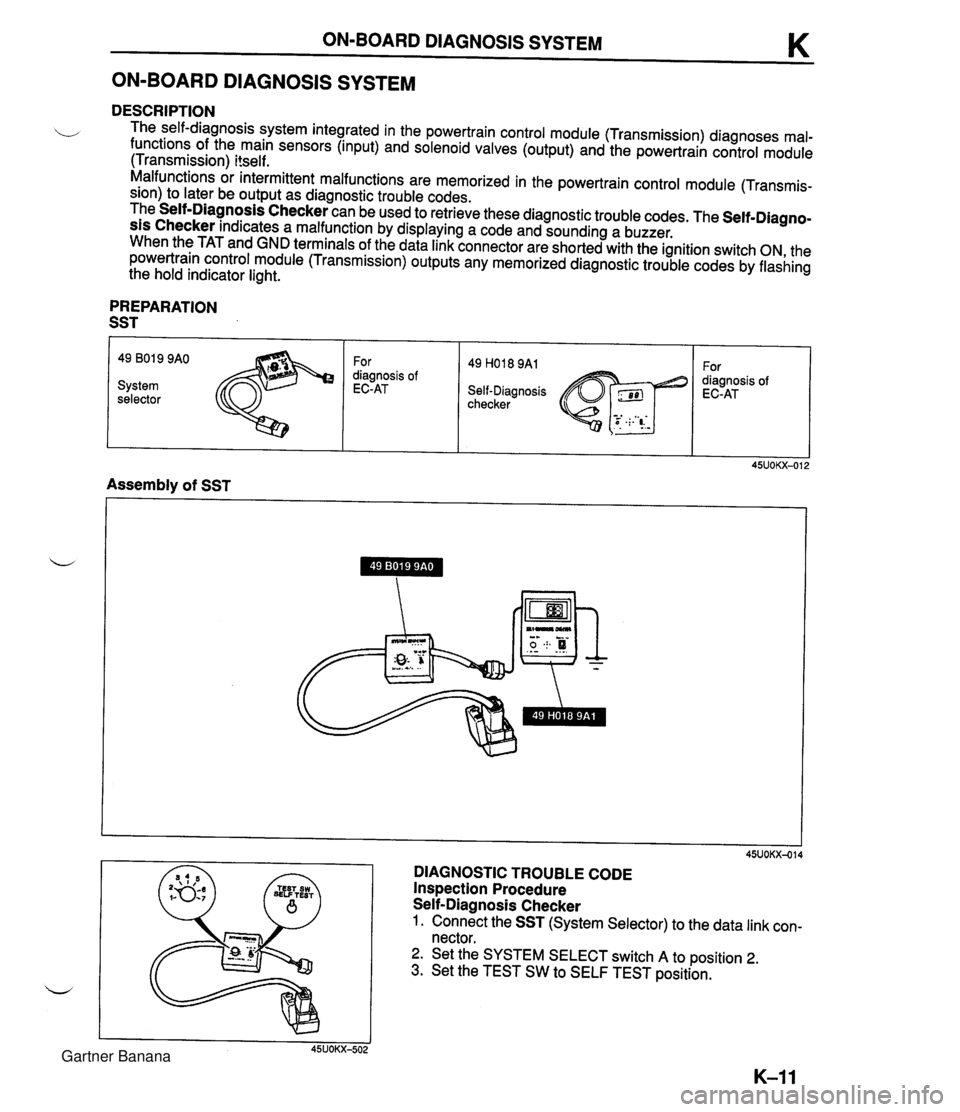
ON-BOARD DIAGNOSIS SYSTEM K ON-BOARD DIAGNOSIS SYSTEM DESCRIPTION The self-diagnosis system integrated in the powertrain control module (Transmission) diagnoses mal- functions of the main sensors (input) and solenoid valves (output) and the powertrain control module (Transmission) itself. Malfunctions or intermittent malfunctions are memorized in the powertrain control module (Transmis- sion) to later be output as diagnostic trouble codes. The Self-Diagnosis Checker can be used to retrieve these diagnostic trouble codes. The Self-Diagno- sis Checker indicates a malfunction by displaying a code and sounding a buzzer. When the TAT and GND terminals of the data link connector are shorted with the ignition switch ON, the powertrain control module (Transmission) outputs any memorized diagnostic trouble codes by flashing the hold indicator light. PREPARATION SST 49 801 9 9AO For 49 H018 9A1 For diagnosis of diagnosis of System EC-AT Self-Diagnosis EC-AT selector checker Assembly of SST DIAGNOSTIC TROUBLE CODE Inspection Procedure Self-Diagnosis Checker 1. Connect the SST (System Selector) to the data link con- nector. 2. Set the SYSTEM SELECT switch A to position 2. 3. Set the TEST SW to SELF TEST position. Gartner Banana
Page 736 of 1708

OUTLINE OUTLINE SPECIFICATIONS Front Suspension - Transmission item (Stabilizer Specifications MT I AT - I Susoension tvoe I . , . , I . , Shock absorber Cylindrical double acting, low-pressure-gas charged I Double-wishbone TY pe Torsion bar Coil spring I - Diameter mm linl I 20.0 10.79) Identification mark color 19.0 (0.75) White Wire diameter mm (in) Coil inner diameter mm {in) I Blue Free length mm {in) Coil number 11 .O (0.43) 83 i3.27) 11 .O (0.43) 83 (3.27) 292.5 (1 1 32) 6.32 3 +. 3 (0.12 + 0.12) 0°18' + 18' Total toe-in I - I 35UORX-001 Rear Suspension 302.0 (1 1.89) 6.32 mm {in) degree Total toe-in (per side) 1 degree Front wheel alignment (Unladedt1) 0°09' +. 09' Caster anglee3 4"26' +. 45' Kingpin angle 11 "20' Maximum steering angle Transmission Specifications MT I AT Item Differential - Suspension type Inner Outer "TORSEN" LSD 1 Standard Double-wishbone Coil springs 370 23' a 2" 32" 32' -t 2" Camber anglee2 Torsion bar 12.0 (0.47) 1 11.0 (0.43) 1 11 .O (0.43) Cylindrical double acting, low-pressure-gas charged - Stabilizer Identification mark color Wire diameter mm {in) 0°24' + 45' Type Diameter mm {in) I Coil number I 7.68 I 7.96 I Shock absorber Yellow 10.1 {0.40} Coil inner diameter mm {in) Free length mm {in) Green 10.2 {0.40) 35UORX-002 *I Fuel tank full; radiator coolant and engine oil at specified levels; spare tire, jack, and tools in designated positions. '2 Difference between left and right must not exceed I O. '3 Difference between left and right must not exceed 1'30'. "TORSEN" is a registered trademark of ZEXEL-GLEASON USA.INC 83 I3.27) 348.5 j13.72) Rear wheel alignment (Unladed*') 83 (3.27) 356.5 (1 4.04) Total toe-in Total toe-in (per side) mm (in) degree degree 3 -c 3 (0.12 + 0.121 0°18' + 18' 0°09' + 09' Camber angle*2 -0°43' 2 30' Gartner Banana