service MAZDA MX-5 1994 Owner's Guide
[x] Cancel search | Manufacturer: MAZDA, Model Year: 1994, Model line: MX-5, Model: MAZDA MX-5 1994Pages: 1708, PDF Size: 82.34 MB
Page 399 of 1708

TRANSMISSION J INSTALLATION 1. On level ground, jack up the vehicle and support it evenly on safety stands. 2. Install in the order shown in the figure, referring to lnstallation Note. L 3. Add the specified amount of the specified transmission oil. (Refer to page J-8.) 4. Warm up the engine and transmission, and inspect for oil leakage and transmission problems. 1. Transmission 7. Exhaust pipe Installation Note ............. page J-46 8. Performance rod 2. Power plant frame (PPF) 9. Differential mounting pipe Installation Note ............. page J-46 10. Undercover 3. S~eedometer cable 11. Shift lever w 4. ~iarter Installation Note ............. page J-47 5. Clutch release cylinder 12. Rear console 6. Propeller shaft 13. Shift lever knob Service ...................... section L Gartner Banana
Page 401 of 1708

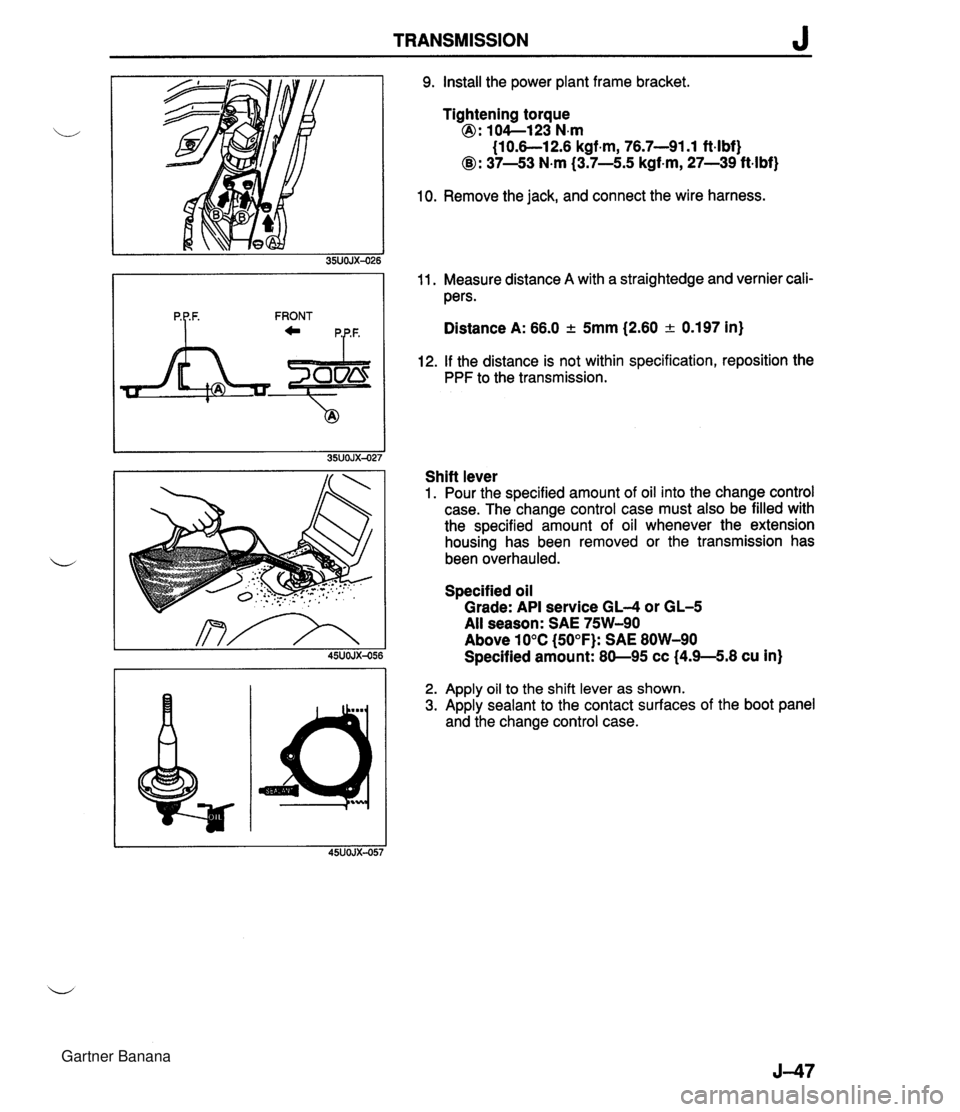
TRANSMISSION J 9. Install the power plant frame bracket. Tightening torque @ : lO4--123 N.m (1 0.6-1 2.6 kgf.m, 76.7-91.1 ft-lbf) @: 37-43 N.m (3.7-5.5 kgf-m, 27-39 ftlbf) 10. Remove the jack, and connect the wire harness. 11. Measure distance A with a straightedge and vernier cali- pers. Distance A: 66.0 2 5mm (2.60 a 0.197 in) 12. If the distance is not within specification, reposition the PPF to the transmission. FRONT Shift lever 1. Pour the specified amount of oil into the change control case. The change control case must also be filled with the specified amount of oil whenever the extension housing has been removed or the transmission has been overhauled. Specified oil Grade: API service GL-4 or GL-5 All season: SAE 75W-90 Above 10°C (50°F): SAE 80W-90 Specified amount: 80-95 cc (4.9-5.8 cu in) 2. Apply oil to the shift lever as shown. 3. Apply sealant to the contact surfaces of the boot panel and the change control case. Gartner Banana
Page 402 of 1708

Before beginning any service procedure. refer to section T of this manual for air bag system service warnings and audio antitheft system alarm conditions . AUTOMATIC TRANSMISSION INDEX ................................ K- 2 OUTLINE ............................. K- 3 SPECIFICATIONS ................... K- 3 ........... CROSS-SECTIONAL VIEW K- 4 POWER FLOW DIAGRAM ............ K- 5 OPERATION OF COMPONENTS ...... K- 5 FLUID PASSAGE LOCATIONS ........ K- 6 TROUBLESHOOTING .................. K- 8 GENERAL NOTES ................... K- 8 .......... QUICK DIAGNOSIS CHART K- 9 ON-BOARD DIAGNOSIS SYSTEM ...... K- 11 DESCRIPTION ...................... K- 11 PREPARATION ...................... K- 11 ....... DIAGNOSTIC TROUBLE CODE K- 11 .......... MECHANICAL SYSTEM TEST K- 22 PREPARATION ...................... K- 22 STALL TEST ........................ K- 22 TIME LAG TEST ..................... K- 25 LINE PRESSURE TEST .............. K- 26 ROAD TEST .......................... K- 29 D-RANGE TEST ..................... K- 29 S-RANGE TEST ..................... K- 31 ..................... L-RANGE TEST K- 32 . P-RANGE TEST ..................... K- 33 AUTOMATIC TRANSMISSION FLUID (ATF) ................................ K- 35 ATF ................................ K- 35 REPLACEMENT ..................... K- 37 ELECTRICAL SYSTEM COMPONENTS . . K- 38 PREPARATION ...................... K- 38 HOLD SWITCH ...................... K- 38 PARWNEUTRAL SWITCH ............ K- 39 .............. ATF THERMOSENSOR K- 41 VEHICLE SPEED PULSE GENERATOR ...................... K- 41 1-2 SHIFT. 2-3 SHIFT. 3-4 SHIFT. ... 3-2 CONTROL SOLENOID VALVE K- 42 LOCKUP CONTROL SOLENOID ....... VALVE ............................ K- 42 POWERTRAIN CONTROL MODULE (TRANSMISSION) .................. K- 43 TRANSMISSION ....................... K- 46 TRANSMISSION UNIT (REMOVAL) .... K- 46 TRANSMISSION UNlT (DISASSEMBLY) ................... K- 50 TORQUE CONVERTER .............. K- 61 OILPUMP .......................... K- 62 FOURTH GEAR CONNECTING SHELL AND FOURTH GEAR PLANETARY GEAR UNIT (FOURTH GEAR SUN GEAR. FOURTH GEAR PLANETARY PINION CARRIER. FOURTH GEAR CLUTCH HUB) ...... K- 67 DIRECT CLUTCH .................... K- 70 FOURTH GEAR BAND SERVO ........ K- 76 DRUM SUPPORT. ACCUMULATOR. AND FOURTH GEAR CASE ......... K- 79 2ND BAND SERVO .................. K- 83 FRONT CLUTCH .................... K- 86 REAR CLUTCH ...................... K- 91 CONNECTING SHELL AND FRONT PLANETARY GEAR UNlT (REAR CLUTCH HUB. FRONT PLANETARY PINION CARRIER. REAR SUN GEAR) ................. K- 96 REAR PLANETARY GEAR UNlT (CONNECTING DRUM. REAR PLANETARY PINION CARRIER. ONE-WAY CLUTCH) K- 98 LOW AND REVERSE BRAKE K-102 ................ ......... EXTENSION HOUSING AND PARKING MECHANISM ............. K-107 OIL SEAL ........................... K-ill CONTROL VALVE BODY ............. K-112 UPPER VALVE BODY ................ K-116 LOWER VALVE BODY ............... K-120 CONTROL VALVE BODY ............. K-125 VACUUM DIAPHRAGM ............... K-130 TRANSMISSION UNIT (ASSEMBLY) ... K-132 TRANSMISSION UNIT (INSTALLATION) ................... K-147 OIL COOLER .......................... K-151 REMOVAL I INSPECTION I INSTALLATION ..................... K-151 DRIVE PLATE ......................... K-152 PREPARATION ...................... K-152 REMOVAL 1 INSPECTION I INSTALLATION ..................... K-152 SHIFT MECHANISM (WITH SHIFT-LOCK SYSTEM) ......... K-154 SHIFT-LOCK SYSTEM COMPONENTS K-154 TROUBLESHOOTING ................ K-155 SHIFT-LOCK ........................ K-157 EMERGENCY OVERRIDE BUTTON ... K-157 KEY INTERLOCK .................... K-157 KEY INTERLOCK SOLENOID ......... K-157 KEY INTERLOCK UNIT ............... K-158 P RANGE SWITCH .................. K-159 SHIFT-LOCKACTUATOR ............. K-159 SELECTOR LEVER .................. K-161 HYDRAULIC CIRCUIT .................. K-168 P RANGE ........................... K-168 R RANGE ........................... K-169 N RANGE; BELOW 7 kmlh I4.34 mph) . K-170 N RANGE; ABOVE 9 kmlh (5.58 mph} . K-171 D RANGE; 1 ST GEAR ................ K-172 D RANGE; 2ND GEAR ............... K-173 D RANGE; THIRD GEAR ............. K-174 D RANGE; FOURTH GEAR. LOCKUP ON ....................... K-175 S RANGE; 1 ST GEAR ................ K-176 S RANGE; 2ND GEAR ............... K-177 S RANGE; THIRD GEAR ............. K-178 L RANGE; 1 ST GEAR ................ K-179 L RANGE; 2ND GEAR ................ K-180 Gartner Banana
Page 586 of 1708

Before beginning any service procedure. refer to section T of this manual for air bag system service warnings and audio antitheft system alarm conditions . FRONT AND REAR AXLES ....................................... INDEX M- 2 ..................................... OUTLINE M- 3 SPECIFICATIONS ........................... M- 3 TROUBLESHOOTING GUIDE .................. M- 4 ............................... FRONT AXLE M- 4 ................................ REAR AXLE M- 4 ............................. DIFFERENTIAL M- 4 ................................. FRONT AXLE M- 5 PREPARATION ............................. M- 5 WHEEL HUB. STEERING KNUCKLE .......... M- 6 .................................. REAR AXLE M-10 PREPARATION ............................. M-10 ......................... DISC BRAKE TYPE M-11 ................................ DRIVE SHAFT M-17 .................... DOUBLE OFFSET JOINT M-17 ............................... DIFFERENTIAL M-23 PREPARATION ............................. M-23 DIFFERENTIAL OIL ......................... M-25 ................. OIL SEAL (OUTPUT SHAFT) M-25 DIFFERENTIAL. STANDARD; DIFFERENTIAL. TORQUE SENSING LIMITED SLIP ("TORSEN" LSD) ........................... M-27 45UOMX-001 "TORSEN" is a registered trademark of ZEXEL-GLEASON USA . INC Gartner Banana
Page 587 of 1708

INDEX INDEX OIL SPECIFICATION ABOVE -1 8°C (O°F1: GL-5. SAE 90 / I 1 ,BELOW -1 8°C Ioo~: GL-5, SAE 80 ..-.. - - - - .. - ...... SERVICE, SECTION L REAR'BRAKE PROPELLER SHACT SERVICE, SECTION P FRONT-BRAKE SERVICE SECTION P 1. Front axle Inspection / Removal / Installation ............... page M- 6 Disassembly 1 Inspection / Assembly. ............... page M- 8 2. Rear axle Inspection / Removal / Installation ............... page M-1 1 Disassembly 1 Inspection / Assembly ................ page M-13 M-2 3. Drive shaft Ins~ection / Removal 1 ............... Installation page M-17 Overhaul .................. page M-19 4. Differential (Standard, Torque sensing limited slip differential) Differential oil .............. page M-25 . Oil seal (Output shaft) ...... page M-25 Removal 1 Installation ....... page M-27 Overhaul .................. page M-32 Gartner Banana
Page 588 of 1708

OUTLINE OUTLINE Front axle Rear axle Differentlal Drive shaft Item I Specifications TY pe Bearing Double-wishbone Angular ball bearing Maximum wheel bearing play mm {in} TY pe Bearing 0.05 {0.002} Double-wishbone Angular ball bearing Maximum wheel bearing play mm {in} Type Reduction gear Reduction ratio Oil I Viscosity 0.05 {0.002} -- ---- Differential gear Ring gear size mm {in} Grade Above -1 8°C {O°F}: SAE 90 Below -1 8°C {O°F}: SAE 80 Standard Hypoid gear Straight-bevel gear 182.88 {7.20) API service GL-5 I Capacity L {US qt. imp qt} I 1 .OO {I .06,0.88) "TORSEN" LSD Worm gear 4.100 TY ~e Length mm {in} Constant velocity (double offset) joint 640.6 I25.220) 45UOMX-00 Gartner Banana
Page 591 of 1708

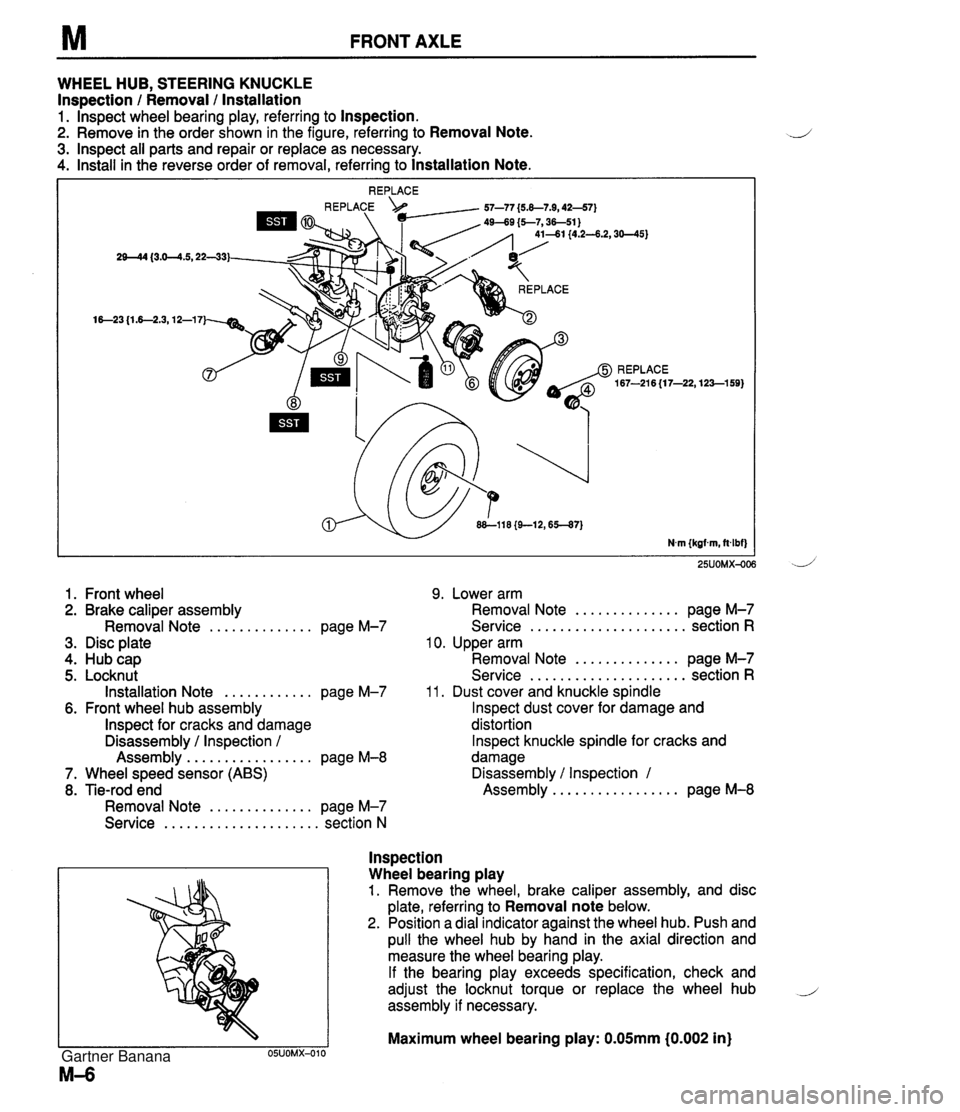
FRONT AXLE WHEEL HUB, STEERING KNUCKLE Inspection / Removal / lnstallation 1. lnspect wheel bearing play, referring to Inspection. 2. Remove in the order shown in the figure, referring to Removal Note. 3. lnspect all parts and repair or replace as necessary. 4. Install in the reverse order of removal, referring to Installation Note. 25UOMX-OC 1. Front wheel 9. Lower arm 2. Brake caliper assembly Removal Note .............. page M-7 3. Disc plate 4. Hub cap 5. Locknut Installation Note ............ page M-7 6. Front wheel hub assembly lnspect for cracks and damage Disassembly / Inspection / Assembly ................. page M-8 7. Wheel speed sensor (ABS) 8. Tie-rod end Removal Note .............. page M-7 Service ..................... section N .............. Removal Note page M-7 ..................... Service section R 10. Upper arm .............. Removal Note page M-7 ..................... Service section R 11. Dust cover and knuckle spindle lnspect dust cover for damage and distortion lnspect knuckle spindle for cracks and damage Disassembly / Inspection 1 ................. Assembly page M-8 lnspection Wheel bearing play 1. Remove the wheel, brake caliper assembly, and disc plate, referring to Removal note below. 2. Position a dial indicator against the wheel hub. Push and pull the wheel hub by hand in the axial direction and measure the wheel bearing play. If the bearing play exceeds specification, check and adjust the locknut torque or replace the wheel hub i assembly if necessary. Maximum wheel bearing play: 0.05mm i0.002 in) Gartner Banana
Page 612 of 1708

DIFFERENTIAL M DIFFERENTIAL, STANDARD; DIFFERENTIAL, TORQUE SENSING LIMITED SLIP ("TORSEN" LSD) Removal 1 lnstallation 1. Drain the differential oil. ,, 2. Remove in the order shown in the figure, referring to Removal Note. 3. Install in the reverse order of removal, referring to lnstallation Note. 4. Add the specified oil to the specified level. 1. Rear wheels 7. Drive shafts 2. Differential mounting pipe Removal Note ............. page M-29 3. Exhaust pipe 8. Differential 4. Propeller shaft Removal Note ............. page M-29 Service ..................... section L Installation Note ........... page M-30 ' 5. Speedometer cable Overhaul .................. page M-32 ,, 6. Power plant frame (PPF), Differential mounting spacer Removal Note ............. page M-28 Installation Note ........... page M-30 Gartner Banana
Page 628 of 1708

Before beginning any service procedure. refer to section T of this manual for I air bag system service warnings and audio antitheft system alarm conditions . STEERING SYSTEM INDEX ....................................... N- 2 OUTLINE ..................................... N- 4 SPECIFICATIONS ........................... N- 4 MANUAL STEERING .......................... N- 4 PREPARATION ............................. N- 4 ................ TROUBLESHOOTING GUIDE N- 5 BOOT ...................................... N- 6 STEERING WHEEL AND COLUMN ........... N- 8 ............. STEERING GEAR AND LINKAGE N-12 ENGINE SPEED SENSING POWER STEERING .......................... N-18 PREPARATION ............................. N-18 TROUBLESHOOTING GUIDE ................ N-20 AIR BLEEDING ............................. N-21 POWER STEERING FLUID ................... N-22 STEERING WHEEL AND COLUMN ........... N-24 STEERING GEAR AND LINKAGE ............. N-25 POWER STEERING OIL PUMP ............... N-33 DRIVE BELT ................................ N-37 25UONX-001 Gartner Banana
Page 666 of 1708

Before beginning any service procedure. refer to section T of this manual for air bag system service warnings and audio antitheft system alarm conditions . BRAKING SYSTEM INDEX ....................................... P- 2 OUTLINE ..................................... P- 4 SPEClFlCATlONS ........................... P- 4 BRAKE SYSTEM ............................. P- 5 PREPARATION ............................. P- 5 TROUBLESHOOTING GUIDE ................ P- 6 AIR BLEEDING ............................. P- 7 BRAKE HYDRAULIC LINE ................... P- 7 BRAKE FLUID .............................. P- 8 ............................. BRAKE PEDAL P- 9 MASTER CYLINDER (STANDARD) ............ P-11 MASTER CYLINDER (ABS) .................. P-14 POWER BRAKE UNIT ....................... P-20 PROPORTIONING BYPASS VALVE ........... P-23 FRONT BRAKE (DISC) ...................... P-25 CALIPER ................................... P-28 REAR BRAKE (DISC) ........................ P-29 CALIPER ................................... P-32 PARKING BRAKE SYSTEM .................... P-34 TROUBLESHOOTING GUIDE ................ P-34 PARKING BRAKE LEVER .................... P-34 PARKING BRAKE CABLE .................... P-36 ANTILOCK BRAKE SYSTEM (ABS) ............ P-37 DESCRIPTION .............................. P-37 PREPARATION ............................. P-37 TROUBLESHOOTING GUIDE ................ P-38 CIRCUIT DIAGRAM ......................... P-52 HYDRAULIC UNIT ........................... P-53 ........................ ABS CONTROL UNIT P-55 RELAYS .................................... P-56 ABS WHEEL SPEED SENSOR (FRONT) ....... P-58 ABS SENSOR ROTOR (FRONT) .............. P-59 ABS WHEEL SPEED SENSOR (REAR) ........ P-60 ABS SENSOR ROTOR (REAR) ............... P-61 25UOPX-001 Gartner Banana