service MAZDA MX-5 1994 Owner's Manual
[x] Cancel search | Manufacturer: MAZDA, Model Year: 1994, Model line: MX-5, Model: MAZDA MX-5 1994Pages: 1708, PDF Size: 82.34 MB
Page 265 of 1708

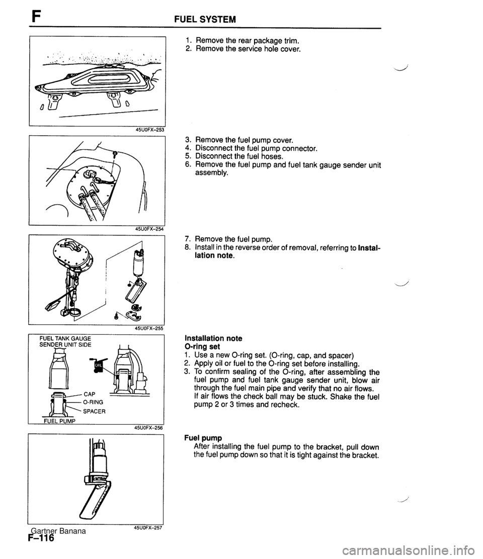
FUEL SYSTEM -- FUEL TANK GAUGE SENDER UNIT SIDE FUEL PUMP 45UOFX-256 1. Remove the rear package trim. 2. Remove the service hole cover. 3. Remove the fuel pump cover. 4. Disconnect the fuel pump connector. 5. Disconnect the fuel hoses. 6. Remove the fuel pump and fuel tank gauge sender unit assembly. 7. Remove the fuel pump. 8. Install in the reverse order of removal, referring to Instal- lation note. Installation note O-ring set 1. Use a new O-ring set. (O-ring, cap, and spacer) 2. Apply oil or fuel to the O-ring set before installing. 3. To confirm sealing of the O-ring, after assembling the fuel pump and fuel tank gauge sender unit, blow air through the fuel main pipe and verify that no air flows. If air flows the check ball may be stuck. Shake the fuel pump 2 or 3 times and recheck. Fuel pump After installing the fuel pump to the bracket, pull down the fuel pump down so that it is tight against the bracket. Gartner Banana
Page 308 of 1708

Before beginning any service procedure. refer to section T of this manual for air bag system service warnings and audio antitheft system alarm conditions . ENGINE ELECTRICAL SYSTEM INDEX ....................................... G- 2 OUTLINE ..................................... G- 3 SPECIFICATIONS ........................... G- 3 TROUBLESHOOTING GUIDE .................. G- 4 CHARGING SYSTEM .......................... G- 6 PREPARATION ............................. G- 6 CIRCUIT DIAGRAM ......................... G- 6 TROUBLESHOOTING ....................... G- 7 BATTERY .................................. G- 8 ALTERNATOR .............................. G-10 DRIVE BELT ................................ G-13 IGNITION SYSTEM ............................ G-15 PREPARATION ............................. G-15 CIRCUIT DIAGRAM ......................... G-15 TROUBLESHOOTING ....................... G-16 IGNITION TIMING ........................... G-17 SPARK PLUG ............................... G-18 IGNITION COIL ............................. G-19 IGNITER ................................... G-19 HIGH-TENSION LEAD ....................... G-20 STARTING SYSTEM ........................... G-21 CIRCUIT DIAGRAM ......................... G-21 TROUBLESHOOTING ....................... G-21 STARTER .................................. G-22 STARTER INTERLOCK SWITCH (MT) ......... G-28 45UOGX401 Gartner Banana
Page 336 of 1708

Before beginning any service procedure. refer to section T of this manual for air bag system service warnlngs and audio antitheft system alarm conditions . i, CLUTCH INDEX ....................................... H- 2 OUTLINE ..................................... H- 3 SPECIFICATIONS ........................... H- 3 TROUBLESHOOTING GUIDE .................. H- 3 CLUTCH FLUID ............................... H- 4 ............................. PREPARATION H- 4 ............................ REPLACEMENT H- 4 .............................. CLUTCH PEDAL H- 5 .............................. ADJUSTMENT H- 5 REMOVAL / INSPECTION / INSTALLATION .... H- 6 ................. CLUTCH MASTER CYLINDER H- 7 PREPARATION ............................. H- 7 REMOVAL / INSTALLATION .................. H- 8 AIR BLEEDING ............................. H- 9 OVERHAUL ................................ H-10 CLUTCH RELEASE CYLINDER ................ H-12 PREPARATION ............................. H-12 REMOVAL / INSTALLATION .................. H-12 AIR BLEEDING (REFER TO PAGE H-9.) OVERHAUL ............................... H-13 CLUTCH UNIT ................................ H-14 PREPARATION ............................. H-14 REMOVAL / INSTALLATION .................. H-14 CLUTCH RELEASE COLLAR .................. H-17 INSPECTION ............................... H-17 CLUTCH COVER ............................. H-17 INSPECTION ............................... H-17 CLUTCH DISC ................................ H-17 INSPECTION ............................... H-17 PILOT BEARING .............................. H-18 INSPECTION ............................... H-18 FLYWHEEL ................................... H-18 INSPECTION ............................... H-18 35UOHX-001 Gartner Banana
Page 337 of 1708

H INDEX INDEX 1 . Clutch pedal ................ Adjustment page H- 5 Removal / Inspection / ............... Installation page H- 6 2. Clutch master cylinder ....... Removal I Installation page H- 8 .................. Overhaul page H-10 ............... Air bleeding page H- 9 3. Clutch release cylinder ....... Removal I Installation page H-12 .................. Overhaul page H-13 ............... Air bleeding page H- 9 4. Clutch release collar ....... Removal / Installation page H-14 ................. Inspection page H-17 SERVICE, SECTION F 5. Clutch release fork ....... Removal / Installation page H-14 6. Clutch cover ....... Removal / Installation page H-14 ................. Inspection page H-17 7. Clutch disc ....... Removal 1 Installation page H-14 ................. Inspection page H-17 8. Pilot bearing ....... Removal I Installation page H-14 ................. Inspection page H-18 9. Flywheel Removal / Installation ....... page H-14 ................. Inspection page H-18 Gartner Banana
Page 350 of 1708

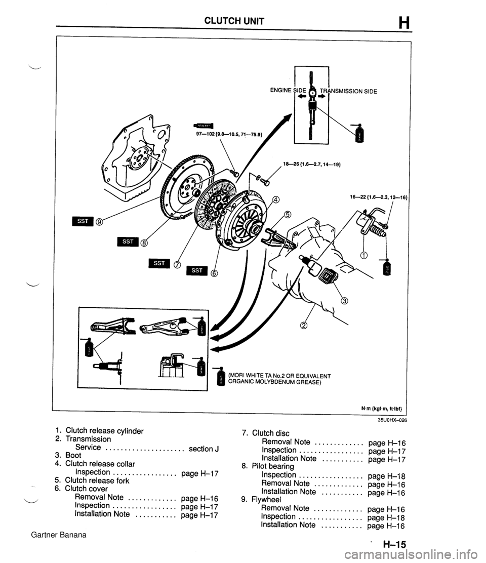
CLUTCH UNIT H 97-1 02 {O&-10.5,71-75.9) 18--26 {I .6-2.7,14-19) (MORI WHITE TA No.2 OR EQUIVALENT ORGANIC MOLYBDENUM GREASE) 1. Clutch release cylinder 2. Transmission Service ..................... section J 3. Boot 4. Clutch release collar Inspection ................. page H-17 5. Clutch release fork 6. Clutch cover Removal Note ............. page H-16 Inspection ................. page H-17 Installation Note ........... page H-17 7. Clutch disc Removal Note ............. page H-16 Inspection ................. page H-17 Installation Note ........... page H-17 8. Pilot bearing Inspection ................. page H-18 Removal Note ............. page H-16 Installation Note ........... page H-16 9. Flywheel Removal Note ............. page H-16 Inspection ................. page H-18 Installation Note ........... page H-16 Gartner Banana
Page 355 of 1708

Before beginning any service procedure. refer to section T of this manual for air bag system service warnings and audio antitheft system alarm conditions . MANUAL TRANSMISSION INDEX ....................................... J- 2 ..................................... OUTLINE J- 3 SPECIFICATIONS ........................... J- 3 ........................ STRUCTURAL VIEW J- 4 ............................. COMPONENTS J- 5 ............................. POWER FLOW J- 6 TROUBLESHOOTING GUIDE .................. J- 7 .......................... TRANSMISSION OIL J- 8 ............................... INSPECTION J- 8 ............................ REPLACEMENT J- 8 TRANSMISSION .............................. J- 9 ............................. PREPARATION J- 9 REMOVAL .................................. J-10 DISASSEMBLY ............................. J-13 ............................... INSPECTION 5-23 ASSEMBLY ................................. J-26 INSTALLATION ............................. J-45 25UOJX-011 Gartner Banana
Page 356 of 1708

J INDEX INDEX OIL SPECIFICATION API SERVICE GL-4 OR GL-5 ALL-SEASON TYPE: SAE 75W-90 ABOVE 10°C {50°F): SAE 80W-90 CAPACITY. 2.0 L {2.1 US qt, 1.8 Imp qt} 1. Transmission Removal . . . . . . . . . . . . . . . . . . . . page J-10 Disassembly . . . . . . . . . . . . . . . . page J-13 Inspection . . . . . . . . . . . . . . . . . . . page J-23 Assembly . . . . . . . . . . . . . . . . . . . page J-26 Installation . . . . . . . . . . . . . . . . . . page J-45 Gartner Banana
Page 357 of 1708

OUTLINE OUTLINE SPECIFICATIONS Transmission Item M15M-D Synchronization mechanism Forward: Synchromesh Reverse: Synchromesh Shift type Gear ratio I st 2nd 5-speed, floor shift 3.1 36 1.888 5th Reverse 0.81 4 3.758 API service GL-4 or GL-5 SAE 75W-90 SAE 80W-90 Grade ' Capacity L {US qt, Imp qt} Viscosity 2.0 12.1, 1.8) All-season Above 10°C {50°F) 45UOJX401 Gartner Banana
Page 362 of 1708

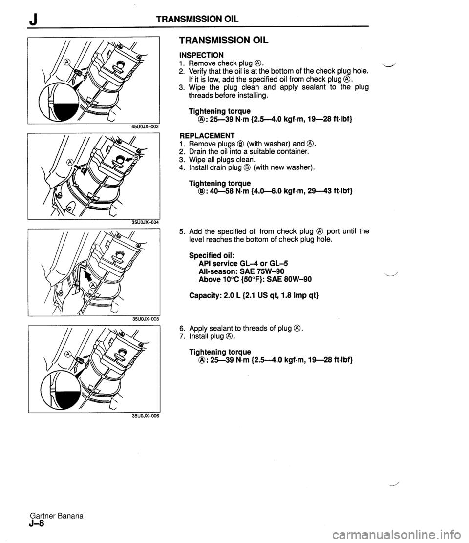
J TRANSMISSION OIL TRANSMISSION OIL INSPECTION 1. Remove check plug 0. u 2. Verify that the oil is at the bottom of the check plug hole. If it is low, add the specified oil from check plug @. 3. Wipe the plug clean and apply sealant to the plug threads before installing. Tightening torque @: 25--39 N.m (2.5--4.0 kgf.m, 19-28 ft4bf) REPLACEMENT 1. Remove plugs @I (with washer) and @. 2. Drain the oil into a suitable container. 3. Wipe all plugs clean. 4. Install drain plug @I (with new washer). Tightening torque @: 40-58 N.m (4.0-4.0 kgf.m, 2943 ftlbf) 5. Add the specified oil from check plug 0 port until the level reaches the bottom of check plug hole. Specified oil: API service GL-4 or GL-5 All-season: SAE 75W-90 Above 10°C (50°F): SAE 80W-90 Capacity: 2.0 L (2.1 US qt, 1.8 Imp qt) 6. Apply sealant to threads of plug 0. 7. lnstall plug @. Tightening torque @: 25--39 N.m (2.54.0 kgf.m, 19-28 ft-lbf) Gartner Banana
Page 364 of 1708

J TRANSMISSION REMOVAL 1. Obtain the code number and deactivate the audio antitheft system before disconnecting the battery. (Refer to section T.) 2. is connect the negative battery cable. 3. On level grand, jack up the vehicle and support it evenly on safety stands. 4. Drain the transmission oil into a suitable container. 5. Remove in the order shown in the figure, referring to Removal Note. I. Shift lever knob ?. Rear console 9. Clutch release cylinder 10. Starter I 1 3. Shift lever 11. speedometer cable 4. Undercover 12. Power plant frame (PPF) 5. Performance rod Removal Note ............... page J-1 1 6. Differential mounting pipe 13. Transmission 7. Exhaust pipe J Removal Note ............... page J-12 8. Propeller shaft Service ...................... section L Gartner Banana