SECTION T MAZDA MX-5 1994 Manual Online
[x] Cancel search | Manufacturer: MAZDA, Model Year: 1994, Model line: MX-5, Model: MAZDA MX-5 1994Pages: 1708, PDF Size: 82.34 MB
Page 343 of 1708
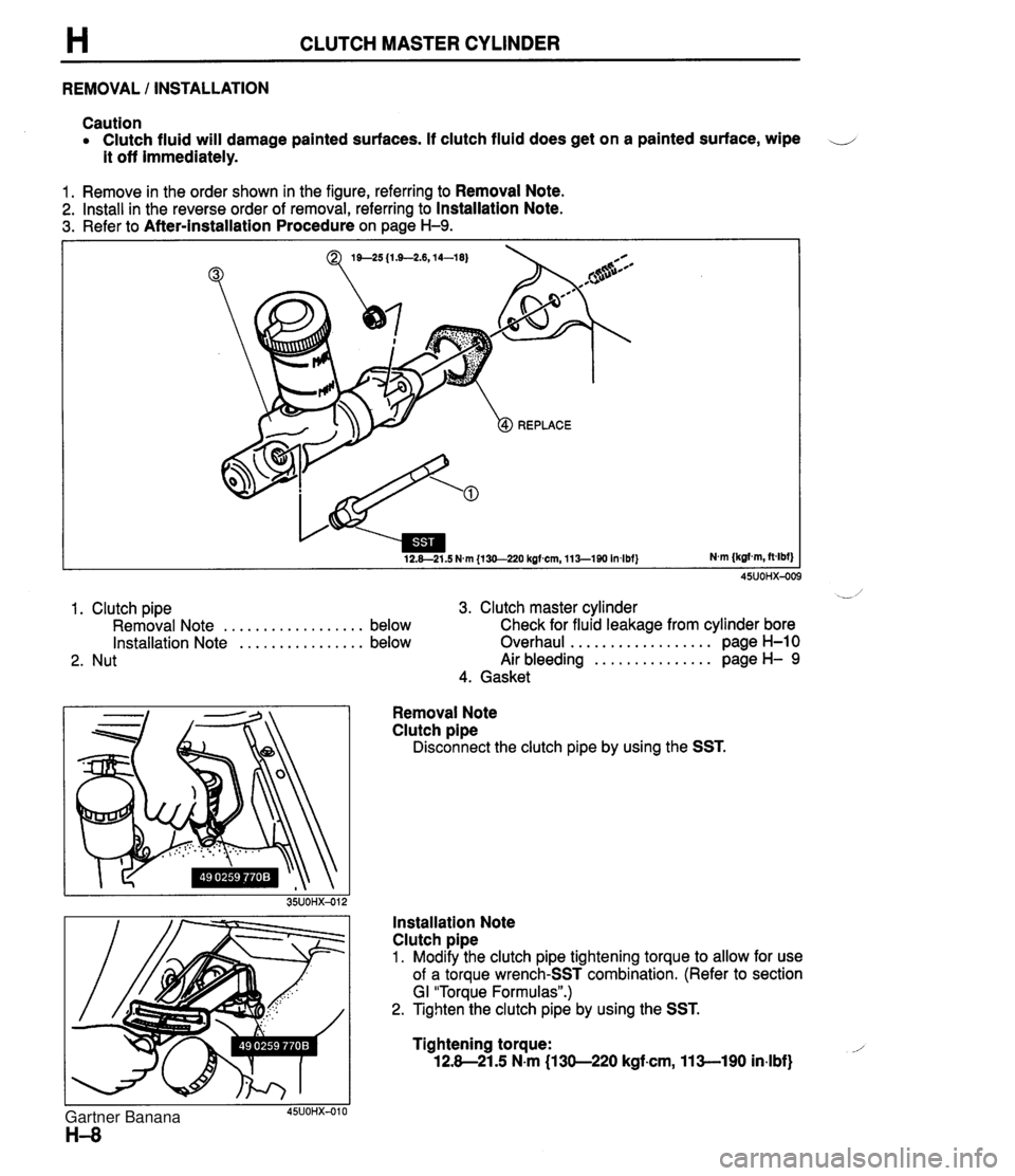
H CLUTCH MASTER CYLINDER REMOVAL I INSTALLATION Caution Clutch fluid will damage painted surfaces. If clutch fluid does get on a painted surface, wipe -. - - - it off immediately. 1. Remove in the order shown in the figure, referring to Removal Note. 2. Install in the reverse order of removal, referring to Installation Note. 3. Refer to After-installation Procedure on page H-9. 1. Clutch pipe 3. Clutch master cylinder Removal Note .................. below Check for fluid leakaae from cvlinder bore 2. Nut " Installation Note ................ below Overhaul .................. page H-10 Air bleeding ............... page H- 9 4. Gasket Removal Note Clutch pipe Disconnect the clutch pipe by using the SST. Installation Note Clutch pipe 1. Modify the clutch pipe tightening torque to allow for use of a torque wrench-SST combination. (Refer to section GI "Torque Formulas".) 2. Tighten the clutch pipe by using the SST. Tightening torque: -1 12.8-21.5 N.m (1 30-220 kgf.cm, 11 %-I90 in.lbf) Gartner Banana
Page 348 of 1708

CLUTCH RELEASE CYLINDER H Installation Note Clutch pipe 1. Modify the clutch pipe tightening torque to allow for use of a torque wrench-SST combination. (Refer to section GI "Torque Formulas".) 2. Tighten the clutch pipe by using the SST. Tightening torque: 12.8-21.5 N-m (1 30-220 kgfam, 11%-190 in-lbf) Air Bleeding After installation, bleed the clutch system. (Refer to page H-9.) OVERHAUL 1. Disassemble in the order shown in the figure, referring to Disassembly Note. 2. lnspect all parts and repair or replace as necessary. Warning Using compressed air can cause dirt and other particles to fly out, causing injury to the eyes. Wear protective eye wear whenever using compressed air. 3. Wipe all parts, and clean all ports, passages, and inner parts with compressed air. 4. Assemble in the reverse order of disassembly. 1. Boot 5. Bleeder cap 2. Push rod 6. Bleeder screw 3. Piston and cup assembly 7. Steel ball Disassembly Note . . . . . . . . . . . . . . . below 8. Release cylinder body Inspect for wear, scoring, and cracks Inspect cylinder bore for scoring and corro- 4. Spring sion Disassembly Note Piston and cup assembly Warning Applying compressed air to the cylinder assem- bly can make the contents suddenly pop out, possibly causing injury. Hold a rag over the cylin- der opening when using compressed air. Remove the piston-and-cup assembly by applying com- pressed air through the clutch pipe installation hole. Gartner Banana
Page 350 of 1708
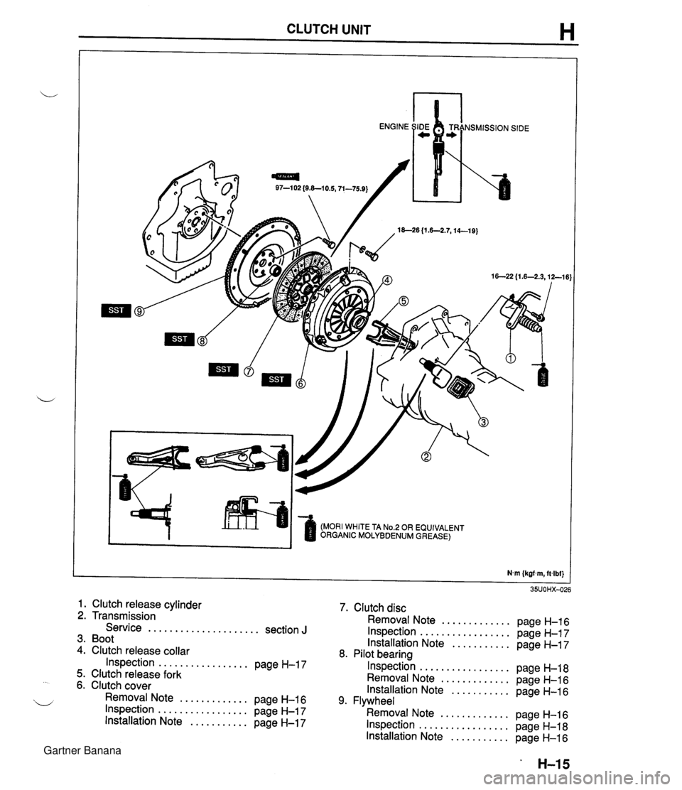
CLUTCH UNIT H 97-1 02 {O&-10.5,71-75.9) 18--26 {I .6-2.7,14-19) (MORI WHITE TA No.2 OR EQUIVALENT ORGANIC MOLYBDENUM GREASE) 1. Clutch release cylinder 2. Transmission Service ..................... section J 3. Boot 4. Clutch release collar Inspection ................. page H-17 5. Clutch release fork 6. Clutch cover Removal Note ............. page H-16 Inspection ................. page H-17 Installation Note ........... page H-17 7. Clutch disc Removal Note ............. page H-16 Inspection ................. page H-17 Installation Note ........... page H-17 8. Pilot bearing Inspection ................. page H-18 Removal Note ............. page H-16 Installation Note ........... page H-16 9. Flywheel Removal Note ............. page H-16 Inspection ................. page H-18 Installation Note ........... page H-16 Gartner Banana
Page 351 of 1708
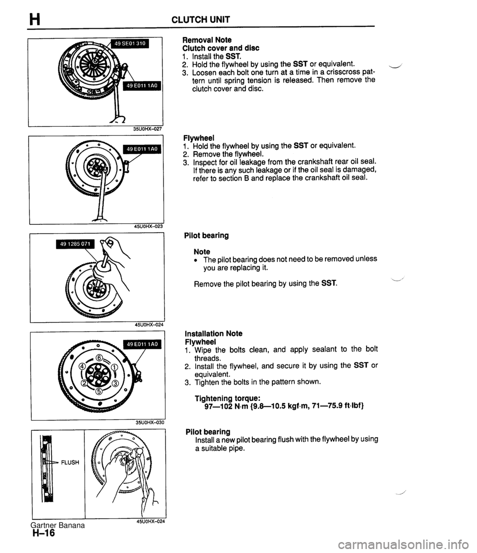
H CLUTCH UNIT Removal Note Clutch cover and disc 1 . Install the SST. 2. Hold the flywheel by using the SST or equivalent. e 3. Loosen each bolt one turn at a time in a crisscross pat- tern until spring tension is released. Then remove the clutch cover and disc. Flywheel 1. Hold the flywheel by using the SST or equivalent. 2. Remove the flywheel. 3. Inspect for oil leakage from the crankshaft rear oil seal. If there is any such leakage or if the oil seal is damaged, refer to section B and replace the crankshaft oil seal. Pilot bearing Note The pilot bearing does not need to be removed unless you are replacing it. Remove the pilot bearing by using the SST. L' Installation Note Flywheel 1. Wipe the bolts clean, and apply sealant to the bolt threads. 2. Install the flywheel, and secure it by using the SST or equivalent. 3. Tighten the bolts in the pattern shown. Tightening torque: 97-1 02 N.m (9.8-1 0.5 kgf.m, 71-75.9 ft-lbf) Pilot bearing Install a new pilot bearing flush with the flywheel by using a suitable pipe. Gartner Banana
Page 355 of 1708

Before beginning any service procedure. refer to section T of this manual for air bag system service warnings and audio antitheft system alarm conditions . MANUAL TRANSMISSION INDEX ....................................... J- 2 ..................................... OUTLINE J- 3 SPECIFICATIONS ........................... J- 3 ........................ STRUCTURAL VIEW J- 4 ............................. COMPONENTS J- 5 ............................. POWER FLOW J- 6 TROUBLESHOOTING GUIDE .................. J- 7 .......................... TRANSMISSION OIL J- 8 ............................... INSPECTION J- 8 ............................ REPLACEMENT J- 8 TRANSMISSION .............................. J- 9 ............................. PREPARATION J- 9 REMOVAL .................................. J-10 DISASSEMBLY ............................. J-13 ............................... INSPECTION 5-23 ASSEMBLY ................................. J-26 INSTALLATION ............................. J-45 25UOJX-011 Gartner Banana
Page 361 of 1708
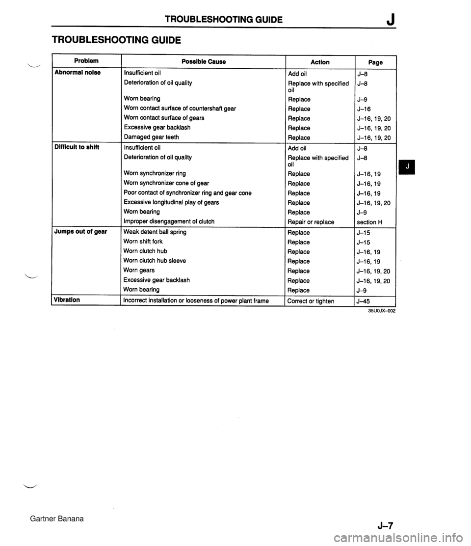
TROUBLESHOOTING GUIDE J TROUBLESHOOTING GUIDE Problem ~bnormal noise lumps out of gear libration Possible Cause nsufficient oil leterioration of oil quality Norn bearing Norn contact surface of countershaft gear Norn contact surface of gears Excessive gear backlash larnaged gear teeth nsufficient oil leterioration of oil quality Worn synchronizer ring Worn synchronizer cone of gear Poor contact of synchronizer ring and gear cone Excessive longitudinal play of gears Worn bearing Improper disengagement of clutch Weak detent ball spring Worn shift fork Worn clutch hub Worn clutch hub sleeve Worn gears Excessive gear backlash Worn bearing Incorrect installation or looseness of power plant frame Action 4dd oil 3eplace with specified )il qeplace 4dd oil 3eplace with specified ~il Replace Replace Replace Replace Replace Repair or replace Replace Replace Replace Replace Replace Replace Replace Correct or tighten Page 5-8 J-8 J-9 J-16 5-1 6,19,20 J-16,19,20 J-16,19,20 J-8 J-8 J-16,19 J-16,19 J-16, 19 J-l6,19,20 J-9 section H J-15 J-15 J-16,19 J-16,19 J-16, 19,20 J-l6,19,20 J-9 J-45 35UOJX-O( Gartner Banana
Page 364 of 1708

J TRANSMISSION REMOVAL 1. Obtain the code number and deactivate the audio antitheft system before disconnecting the battery. (Refer to section T.) 2. is connect the negative battery cable. 3. On level grand, jack up the vehicle and support it evenly on safety stands. 4. Drain the transmission oil into a suitable container. 5. Remove in the order shown in the figure, referring to Removal Note. I. Shift lever knob ?. Rear console 9. Clutch release cylinder 10. Starter I 1 3. Shift lever 11. speedometer cable 4. Undercover 12. Power plant frame (PPF) 5. Performance rod Removal Note ............... page J-1 1 6. Differential mounting pipe 13. Transmission 7. Exhaust pipe J Removal Note ............... page J-12 8. Propeller shaft Service ...................... section L Gartner Banana
Page 368 of 1708
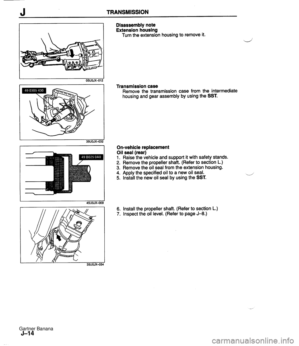
J TRANSMISSION Disassembly note Extension housing Turn the extension housing to remove it. Transmission case Remove the transmission case from the intermediate housing and gear assembly by using the SST. On-vehicle replacement Oil seal (rear) 1. Raise the vehicle and support it with safety stands. 2. Remove the propeller shaft. (Refer to section L.) 3. Remove the oil seal from the extension housing. 4. Apply the specified oil to a new oil seal. 5. Install the new oil seal by using the SST. 6. Install the propeller shaft. (Refer to section L.) 7. Inspect the oil level. (Refer to page J-8.) Gartner Banana
Page 399 of 1708

TRANSMISSION J INSTALLATION 1. On level ground, jack up the vehicle and support it evenly on safety stands. 2. Install in the order shown in the figure, referring to lnstallation Note. L 3. Add the specified amount of the specified transmission oil. (Refer to page J-8.) 4. Warm up the engine and transmission, and inspect for oil leakage and transmission problems. 1. Transmission 7. Exhaust pipe Installation Note ............. page J-46 8. Performance rod 2. Power plant frame (PPF) 9. Differential mounting pipe Installation Note ............. page J-46 10. Undercover 3. S~eedometer cable 11. Shift lever w 4. ~iarter Installation Note ............. page J-47 5. Clutch release cylinder 12. Rear console 6. Propeller shaft 13. Shift lever knob Service ...................... section L Gartner Banana
Page 402 of 1708

Before beginning any service procedure. refer to section T of this manual for air bag system service warnings and audio antitheft system alarm conditions . AUTOMATIC TRANSMISSION INDEX ................................ K- 2 OUTLINE ............................. K- 3 SPECIFICATIONS ................... K- 3 ........... CROSS-SECTIONAL VIEW K- 4 POWER FLOW DIAGRAM ............ K- 5 OPERATION OF COMPONENTS ...... K- 5 FLUID PASSAGE LOCATIONS ........ K- 6 TROUBLESHOOTING .................. K- 8 GENERAL NOTES ................... K- 8 .......... QUICK DIAGNOSIS CHART K- 9 ON-BOARD DIAGNOSIS SYSTEM ...... K- 11 DESCRIPTION ...................... K- 11 PREPARATION ...................... K- 11 ....... DIAGNOSTIC TROUBLE CODE K- 11 .......... MECHANICAL SYSTEM TEST K- 22 PREPARATION ...................... K- 22 STALL TEST ........................ K- 22 TIME LAG TEST ..................... K- 25 LINE PRESSURE TEST .............. K- 26 ROAD TEST .......................... K- 29 D-RANGE TEST ..................... K- 29 S-RANGE TEST ..................... K- 31 ..................... L-RANGE TEST K- 32 . P-RANGE TEST ..................... K- 33 AUTOMATIC TRANSMISSION FLUID (ATF) ................................ K- 35 ATF ................................ K- 35 REPLACEMENT ..................... K- 37 ELECTRICAL SYSTEM COMPONENTS . . K- 38 PREPARATION ...................... K- 38 HOLD SWITCH ...................... K- 38 PARWNEUTRAL SWITCH ............ K- 39 .............. ATF THERMOSENSOR K- 41 VEHICLE SPEED PULSE GENERATOR ...................... K- 41 1-2 SHIFT. 2-3 SHIFT. 3-4 SHIFT. ... 3-2 CONTROL SOLENOID VALVE K- 42 LOCKUP CONTROL SOLENOID ....... VALVE ............................ K- 42 POWERTRAIN CONTROL MODULE (TRANSMISSION) .................. K- 43 TRANSMISSION ....................... K- 46 TRANSMISSION UNIT (REMOVAL) .... K- 46 TRANSMISSION UNlT (DISASSEMBLY) ................... K- 50 TORQUE CONVERTER .............. K- 61 OILPUMP .......................... K- 62 FOURTH GEAR CONNECTING SHELL AND FOURTH GEAR PLANETARY GEAR UNIT (FOURTH GEAR SUN GEAR. FOURTH GEAR PLANETARY PINION CARRIER. FOURTH GEAR CLUTCH HUB) ...... K- 67 DIRECT CLUTCH .................... K- 70 FOURTH GEAR BAND SERVO ........ K- 76 DRUM SUPPORT. ACCUMULATOR. AND FOURTH GEAR CASE ......... K- 79 2ND BAND SERVO .................. K- 83 FRONT CLUTCH .................... K- 86 REAR CLUTCH ...................... K- 91 CONNECTING SHELL AND FRONT PLANETARY GEAR UNlT (REAR CLUTCH HUB. FRONT PLANETARY PINION CARRIER. REAR SUN GEAR) ................. K- 96 REAR PLANETARY GEAR UNlT (CONNECTING DRUM. REAR PLANETARY PINION CARRIER. ONE-WAY CLUTCH) K- 98 LOW AND REVERSE BRAKE K-102 ................ ......... EXTENSION HOUSING AND PARKING MECHANISM ............. K-107 OIL SEAL ........................... K-ill CONTROL VALVE BODY ............. K-112 UPPER VALVE BODY ................ K-116 LOWER VALVE BODY ............... K-120 CONTROL VALVE BODY ............. K-125 VACUUM DIAPHRAGM ............... K-130 TRANSMISSION UNIT (ASSEMBLY) ... K-132 TRANSMISSION UNIT (INSTALLATION) ................... K-147 OIL COOLER .......................... K-151 REMOVAL I INSPECTION I INSTALLATION ..................... K-151 DRIVE PLATE ......................... K-152 PREPARATION ...................... K-152 REMOVAL 1 INSPECTION I INSTALLATION ..................... K-152 SHIFT MECHANISM (WITH SHIFT-LOCK SYSTEM) ......... K-154 SHIFT-LOCK SYSTEM COMPONENTS K-154 TROUBLESHOOTING ................ K-155 SHIFT-LOCK ........................ K-157 EMERGENCY OVERRIDE BUTTON ... K-157 KEY INTERLOCK .................... K-157 KEY INTERLOCK SOLENOID ......... K-157 KEY INTERLOCK UNIT ............... K-158 P RANGE SWITCH .................. K-159 SHIFT-LOCKACTUATOR ............. K-159 SELECTOR LEVER .................. K-161 HYDRAULIC CIRCUIT .................. K-168 P RANGE ........................... K-168 R RANGE ........................... K-169 N RANGE; BELOW 7 kmlh I4.34 mph) . K-170 N RANGE; ABOVE 9 kmlh (5.58 mph} . K-171 D RANGE; 1 ST GEAR ................ K-172 D RANGE; 2ND GEAR ............... K-173 D RANGE; THIRD GEAR ............. K-174 D RANGE; FOURTH GEAR. LOCKUP ON ....................... K-175 S RANGE; 1 ST GEAR ................ K-176 S RANGE; 2ND GEAR ............... K-177 S RANGE; THIRD GEAR ............. K-178 L RANGE; 1 ST GEAR ................ K-179 L RANGE; 2ND GEAR ................ K-180 Gartner Banana