clutch MAZDA MX-5 1994 Manual Online
[x] Cancel search | Manufacturer: MAZDA, Model Year: 1994, Model line: MX-5, Model: MAZDA MX-5 1994Pages: 1708, PDF Size: 82.34 MB
Page 461 of 1708
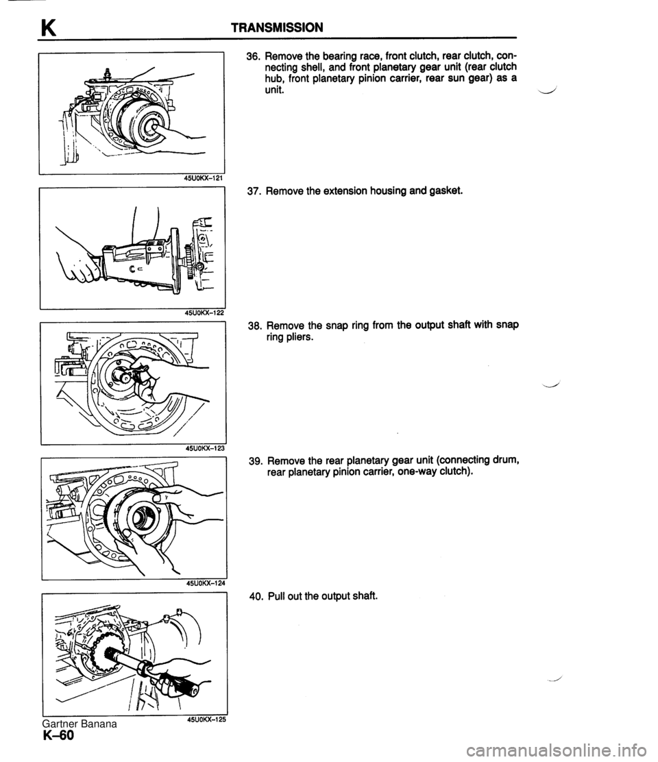
K TRANSMISSION 36. Remove the bearing race, front clutch, rear clutch, con- necting shell, and front planetary gear unit (rear clutch hub, front planetary pinion carrier, rear sun gear) as a unit. d 37. Remove the extension housing and gasket. 38. Remove the snap ring from the output shaft with snap ring pliers. 39. Remove the rear planetary gear unit (connecting drum, rear planetary pinion carrier, one-way clutch). 40. Pull out the output shaft. Gartner Banana
Page 468 of 1708
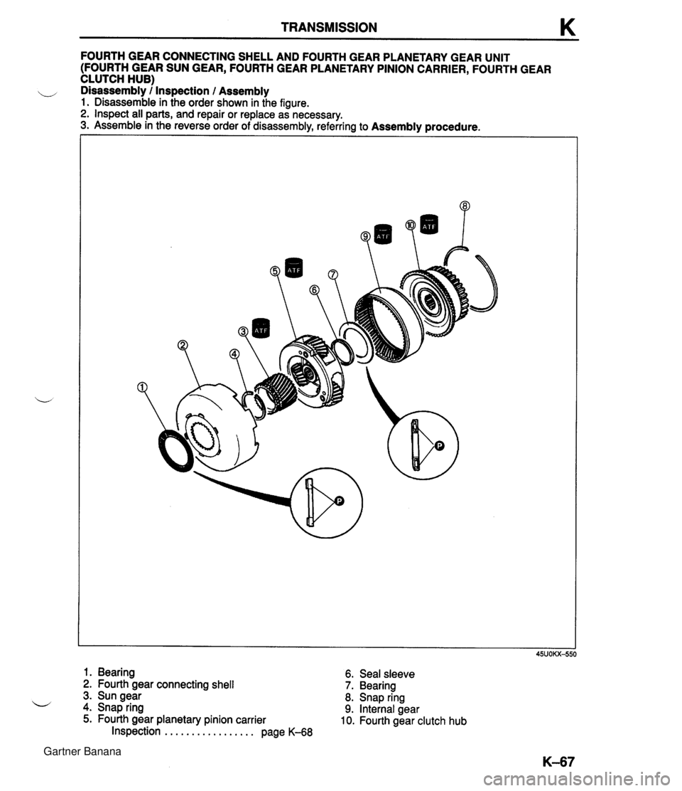
TRANSMISSION K FOURTH GEAR CONNECTING SHELL AND FOURTH GEAR PLANETARY GEAR UNIT (FOURTH GEAR SUN GEAR, FOURTH GEAR PLANETARY PINION CARRIER, FOURTH GEAR CLUTCH HUB) ,, Disassembly / Inspection l Assembly 1. Disassemble in the order shown in the figure. 2. Inspect all parts, and repair or replace as necessary. 3. Assemble in the reverse order of disassembly, referring to Assembly procedure. 1. Bearing 6. Seal sleeve 2. Fourth gear connecting shell 7. Bearing 3. Sun gear 8. Snap ring 4. Snap ring 9. Internal gear 5. Fourth gear planetary pinion carrier 10. Fourth gear clutch hub Inspection . . . . . . . . . . . . . . . . . page K-68 Gartner Banana
Page 469 of 1708
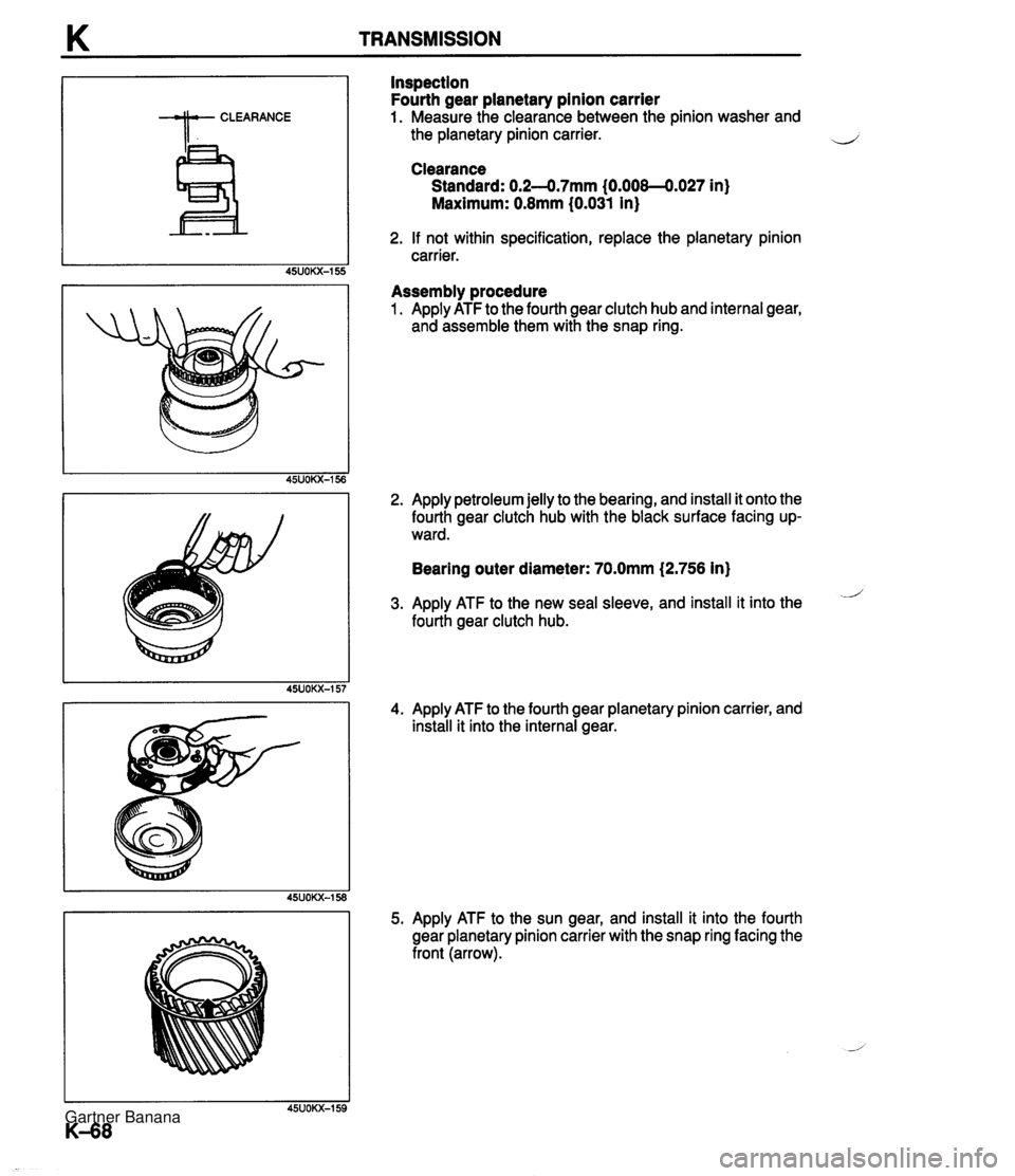
K TRANSMISSION Inspection Fourth gear planetary pinion carrier 1. Measure the clearance between the pinion washer and the planetary pinion carrier. Clearance Standard: 0.2--0.7mm (0.008-4.027 in) Maximum: 0.8mm (0.031 in) 2. If not within specification, replace the planetary pinion carrier. Assembly procedure 1. Apply ATF to the fourth gear clutch hub and internal gear, and assemble them with the snap ring. 2. Apply petroleum jelly to the bearing, and install it onto the fourth gear clutch hub with the black surface facing up- ward. Bearing outer diameter: 70.0mm (2,756 in) i 3. Apply ATF to the new seal sleeve, and install it into the fourth gear clutch hub. 4. Apply ATF to the fourth gear planetary pinion carrier, and install it into the internal gear. 5. Apply ATF to the sun gear, and install it into the fourth gear planetary pinion carrier with the snap ring facing the front (arrow). Gartner Banana
Page 471 of 1708
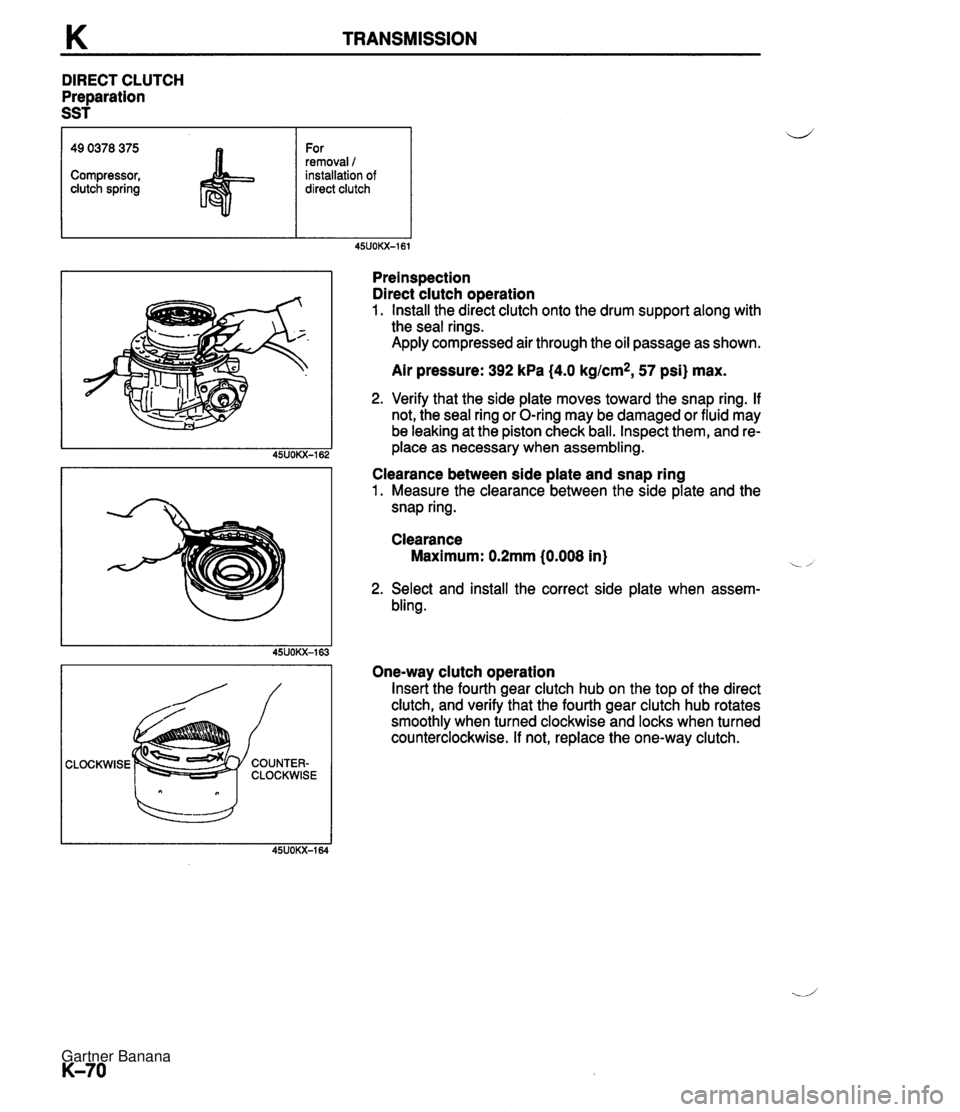
K TRANSMISSION DIRECT CLUTCH Preparation SST CLOCKWISE 49 0378 375 Compressor, clutch spring Preinspection Direct clutch operation 1. Install the direct clutch onto the drum support along with the seal rings. Apply compressed air through the oil passage as shown. For removal 1 installation of direct clutch Air pressure: 392 kPa (4.0 kgtcm*, 57 psi) max. 2. Verify that the side plate moves toward the snap ring. If not, the seal ring or O-ring may be damaged or fluid may be leaking at the piston check ball. Inspect them, and re- place as necessary when assembling. Clearance between side plate and snap ring 1. Measure the clearance between the side plate and the snap ring. Clearance Maximum: 0.2mm (0.008 in) i -, 2. Select and install the correct side plate when assern- bling. One-way clutch operation Insert the fourth gear clutch hub on the top of the direct clutch, and verify that the fourth gear clutch hub rotates smoothly when turned clockwise and locks when turned counterclockwise. If not, replace the one-way clutch. Gartner Banana
Page 472 of 1708
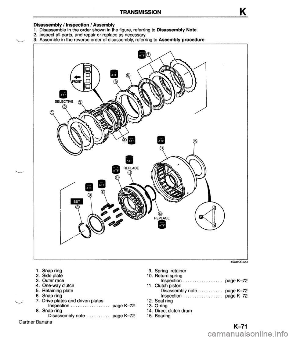
TRANSMISSION K Disassembly I Inspection I Assembly 1. Disassemble in the order shown in the figure, referring to Disassembly Note. 2. Inspect all parts, and repair or replace as necessary. 3. Assemble in the reverse order of disassembly, referring to Assembly procedure. 1. Snap ring 2. Side plate 9. Spring retainer 10. Return spring . - 3. Outer race Inspection ................. page K-72 4. One-way clutch 11. Clutch piston 5. Retaining plate Disassembly note .......... page K-72 6. Snap ring Inspection ................. page K-72 u 7. Drive plates and driven plates 12. Seal ring Inspection ................. page K-72 13. O-ring 8. Snap ring 14. Direct clutch drum Disassembly note .......... page K-72 15. Bearing Gartner Banana
Page 473 of 1708
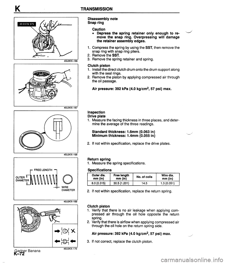
WIRE DIAMETER Disassembly note Snap ring Caution Depress the spring retainer only enough to re- d move the snap ring. Overpressing will damage the retainer assembly edges. 1. Compress the spring by using the SST, then remove the snap ring with snap ring pliers. 2. Remove the SST. 3. Remove the spring retainer and spring. Clutch piston 1. Install the direct clutch drum onto the drum support along with the seal rings. 2. Remove the piston by applying compressed air through the oil passage. Air pressure: 392 kPa {4.0 kglcm2, 57 psi) max. Inspection Drive plate 1. Measure the facing thickness in three places, and deter- mine the average of the three readings. Standard thickness: 1.6mm (0.063 in) Minimum thickness: 1.4mm (0.055 in) 2. If not within specification, replace the drive plates. Return spring 1. Measure the spring specifications. Specifications 2. If not within specification, replace the return spring. Clutch piston 1. Verify that there is no air leakage when applying com- pressed air through the oil hole opposite the return spring. 2. Verify that there is airflow when applying compressed air through the oil hole on the return spring side. - Outer dia mm {in) 8.0 (0.315) Air pressure: 392 kPa (4.0 kg/cm2, 57 psi) max. No. ,oils 14.5 - Free length mm {in) 30.5 {1.201} 3. If not correct, replace the clutch piston. Wire dia. rnm {in) 1.3 (0.051) Gartner Banana
Page 474 of 1708
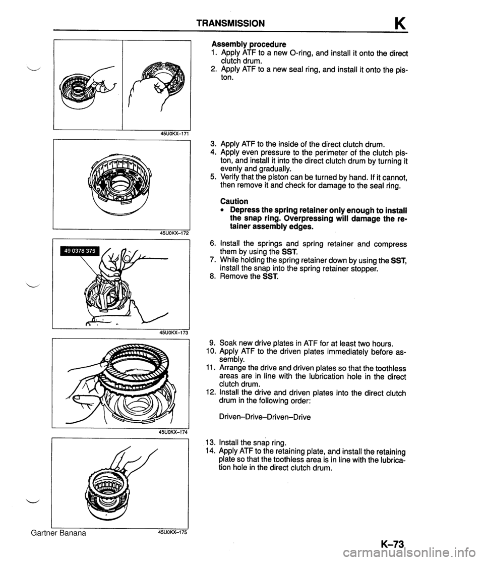
TRANSMISSION K Assembly procedure 1. Apply ATF to a new O-ring, and install it onto the direct clutch drum. 2. Apply ATF to a new seal ring, and install it onto the pis- ton. 3. Apply ATF to the inside of the direct clutch drum. 4. Apply even pressure to the perimeter of the clutch pis- ton, and install it into the direct clutch drum by turning it evenly and gradually. 5. Verify that the piston can be turned by hand. If it cannot, then remove it and check for damage to the seal ring. Caution Depress the spring retainer only enough to install the snap ring. Overpressing will damage the re- tainer assembly edges. 6. Install the springs and spring retainer and compress them by using the SST. 7. While holding the spring retainer down by using the SST, install the snap into the spring retainer stopper. 8. Remove the SST. 9. Soak new drive plates in ATF for at least two hours. 10. Apply ATF to the driven plates immediately before as- sembly. 11. Arrange the drive and driven plates so that the toothless areas are in line with the lubrication hole in the direct clutch drum. 12. Install the drive and driven plates into the direct clutch drum in the following order: Driven-Drive-Driven-Drive 13. Install the snap ring. 14. Apply ATF to the retaining plate, and install the retaining plate so that the toothless area is in line with the lubrica- tion hole in the direct clutch drum. Gartner Banana
Page 475 of 1708
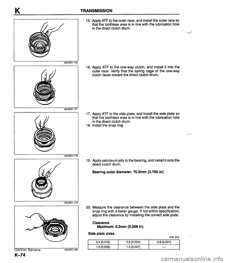
TRANSMISSION 15. Apply ATF to the outer race, and install the outer race so that the toothless area is in line with the lubrication hole in the direct clutch drum. d 16. Apply ATF to the one-way clutch, and install it into the outer race. Verify that the spring cage of the one-way clutch faces toward the direct clutch drum. 17. Apply ATF to the side plate, and install the side plate so that the toothless area is in line with the lubrication hole in the direct clutch drum. 18. Install the snap ring. 19. Apply petroleum jelly to the bearing, and install it onto the direct clutch drum. Bearing outer diameter: 70.0mm (2.756 in) 20. Measure the clearance between the side plate and the snap ring with a feeler gauge. If not within specification, adjust the clearance by installing the correct side plate. Clearance Maximum: 0.2mm (0.008 in) Side plate sizes mm {in) - Gartner Banana
Page 476 of 1708

TRANSMISSION K 21. Insert the fourth gear clutch hub on the top of the direct clutch and verify that the fourth gear clutch hub rotates smoothly when turned clockwise and locks when turned counterclockwise. If it does not, then the one-way clutch is installed upside down. Caution Applying compressed air to the assembled clutch pack for longer than 3 seconds at a time will dam- age the seal. 22. Install the direct clutch onto the drum support along with the seal rings. Apply compressed air to the oil passage and check the clutch operation. Air pressure: 392 kPa {4.0 kglcm2, 67 psi) max. Gartner Banana
Page 482 of 1708

TRANSMISSION K 2. Apply ATF to the spring and install it into the fourth gear case. 3. Apply ATF to the accumulator piston. 4. Apply even pressure to the perimeter of the piston, and install it into the fourth gear case. 5. Verify that the piston can be turned by hand. If it cannot, then remove it and check for damage to the seal ring. 6. Apply ATF to a new O-ring, and install it on the accumula- tor plug. 7. Install the accumulator plug and snap ring. Caution Applying compressed air to the assembled clutch pack for longer than 3 seconds at a time will dam- age the seal. 8. Check the accumulator operation by applying com- pressed air through the oil passage. Air pressure: 392 kPa (4.0 kg/cm2, 57 psi) max. 9. Apply ATF to the plug, and install it into the drum support. 10. Tap in a new roll pin. 11. Set the oil pump onto the SST. 12. Apply ATF to a new seal ring, and install it onto the drum support. Gartner Banana