instrument panel MAZDA MX-5 1994 Workshop Manual
[x] Cancel search | Manufacturer: MAZDA, Model Year: 1994, Model line: MX-5, Model: MAZDA MX-5 1994Pages: 1708, PDF Size: 82.34 MB
Page 440 of 1708

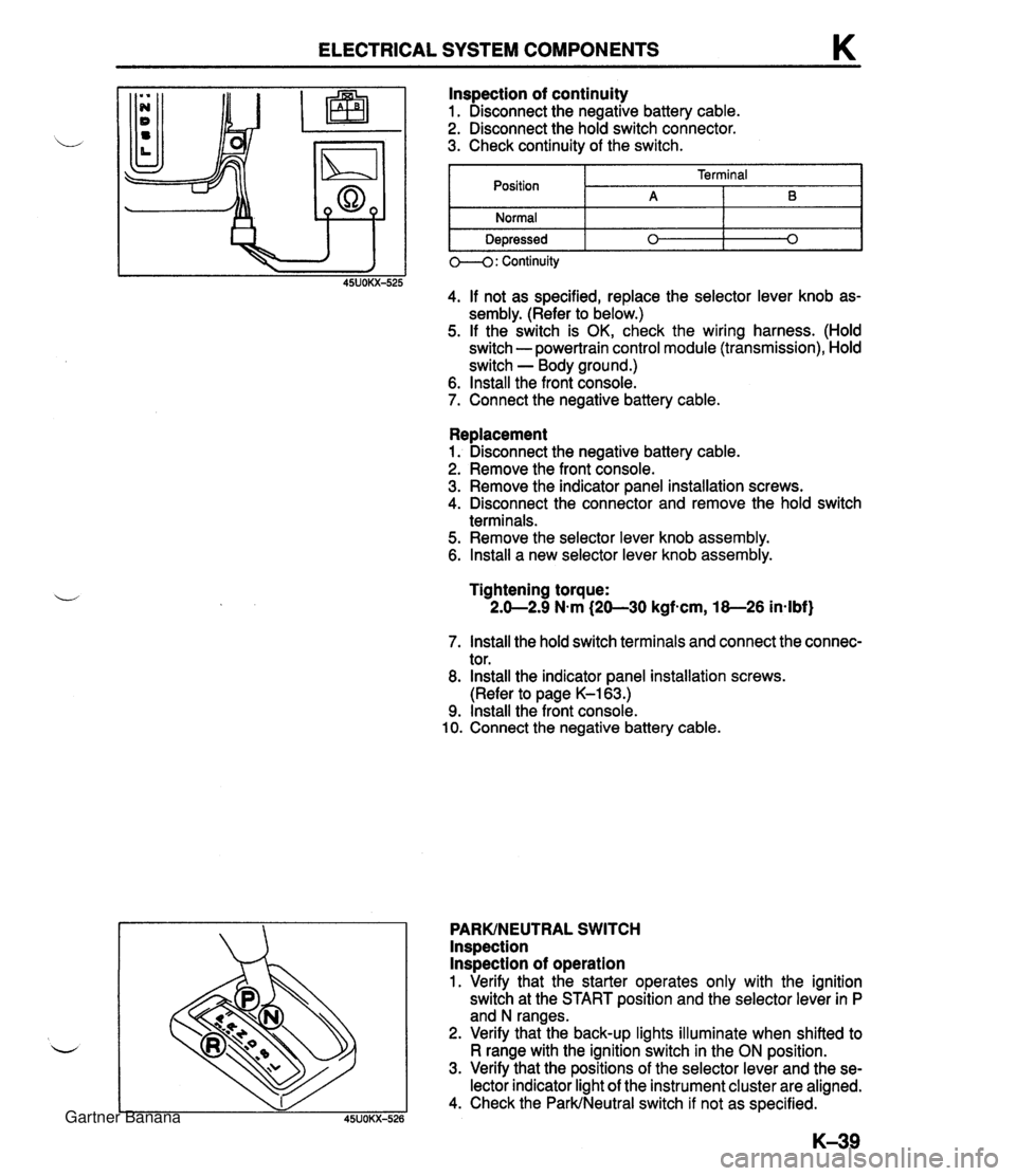
ELECTRICAL SYSTEM COMPONENTS K Replacement 1. Disconnect the negative battery cable. 2. Remove the front console. 3. Remove the indicator panel installation screws. 4. Disconnect the connector and remove the hold switch terminals. 5. Remove the selector lever knob assembly. 6. lnstall a new selector lever knob assembly. lnspection of continuity 1. Disconnect the negative battery cable. 2. Disconnect the hold switch connector. 3. Check continuity of the switch. Tightening torque: 2.0-2.9 N.m (20-30 kgfscm, 18-26 in-lbf) Position Normal Depressed 7. lnstall the hold switch terminals and connect the connec- tor. 8. lnstall the indicator panel installation screws. (Refer to page K-163.) 9. lnstall the front console. 10. Connect the negative battery cable. PARKINEUTRAL SWITCH lnspection lnspection of operation 1. Verify that the starter operates only with the ignition switch at the START position and the selector lever in P and N ranges. 2. Verify that the back-up lights illuminate when shifted to R range with the ignition switch in the ON position. 3. Verify that the positions of the selector lever and the se- lector indicator light of the instrument cluster are aligned. 4. Check the ParkINeutral switch if not as specified. 0--4: Continuity 45UOKX-525 4. If not as specified, replace the selector lever knob as- sembly. (Refer to below.) 5. If the switch is OK, check the wiring harness. (Hold switch - powertrain control module (transmission), Hold switch - Body ground.) 6. lnstall the front console. 7. Connect the negative battery cable. Terminal A 0 B 0 Gartner Banana
Page 814 of 1708

DASHBOARD AND CONSOLE DASHBOARD AND CONSOLE COMPONENTS Removal l Installation 1. Disconnect the negative battery cable. Warning Handling the air bag module improperly can accidently deploy the air bag, which may seri- ously injure you. Read SERVICE WARNINGS, section T, before handling the air bag module. 2. Remove in the order shown in the figure, referring to Removal Note. To remove the dashboard, remove the control wires of the heater unit and blower unit. 3. Install in the reverse order of removal. 1. Ashtray 2. Change lever knob 3. Rear console assembly a. Back plate b. Shift lever boot 7. Speedometer cable 8. Instrument cluster 9. Center louver Removal Note ............. page S-57 10. Center an el assemblv c. Power window switch Removal Note ............. page S-58 d. Cover (Without power window) 1 1. Glove box assembly e. Console lock assembly 12. Passenger-side airbag module (if equipped) 4. Center lower panel assembly Removal 1 Installation ......... section T Removal Note ............. page S-57 13. Hood release knob -1 5. Steering shaft 14. Center hole cover 6. Meter hood assembly 15. Side cover Removal Note ............. page $57 16. Dashboard Gartner Banana
Page 1275 of 1708

CONSTRUCTION No. 0 Part Name Bumper bracket Hood (Bonnet) 1 8 / Front frame, upper rear Crossmember No. 1 Shroud panel assy Radiator bracket No. @ Dash side junction I @ / Front frame, rear Part Name Crossmember No. 2 @ @I @ Light lid Dash panel assy Seat bracket No. 3 gusset Front frame, upper front Dash panel assy I @ / Stabilizer bracket @ @I Cowl panel, front Instrument bracket Apron reinforcement Front wheel apron assy I @ I Front wheel apron panel Q Tie-down hook reinforcement Front floor side pan Tunnel side junction Front frame @ @ Front fender panel Torque box Gartner Banana
Page 1298 of 1708

PANEL REPLACEMENT FRONT PILLAR, OUTER COWL SlDE PANEL, HINGE PILLAR, INNER COWL SlDE PANEL AND SlDE SILL PANEL REMOVAL cut-and-join location I The following operations are performed when the inner and outer front pillars, cowl side panel, outer hinge pillar, inner cowl side panel, and outer side sill panel are replaced at the same time. Cut away the joint of the outer front pillar and the upper front header (shown by the broken line) with a saw. Rough-cut the outer side sill panel and drill away the spot welding of the hinge pillar and the side sill reinforcement. Do not make open holes when drilling. Cut away the other welded points shown in the illustration. Remove the bolts attached to the instrument panel bracket, the dash side junction, etc. Remove the parts to be replaced. -- Gartner Banana
Page 1570 of 1708

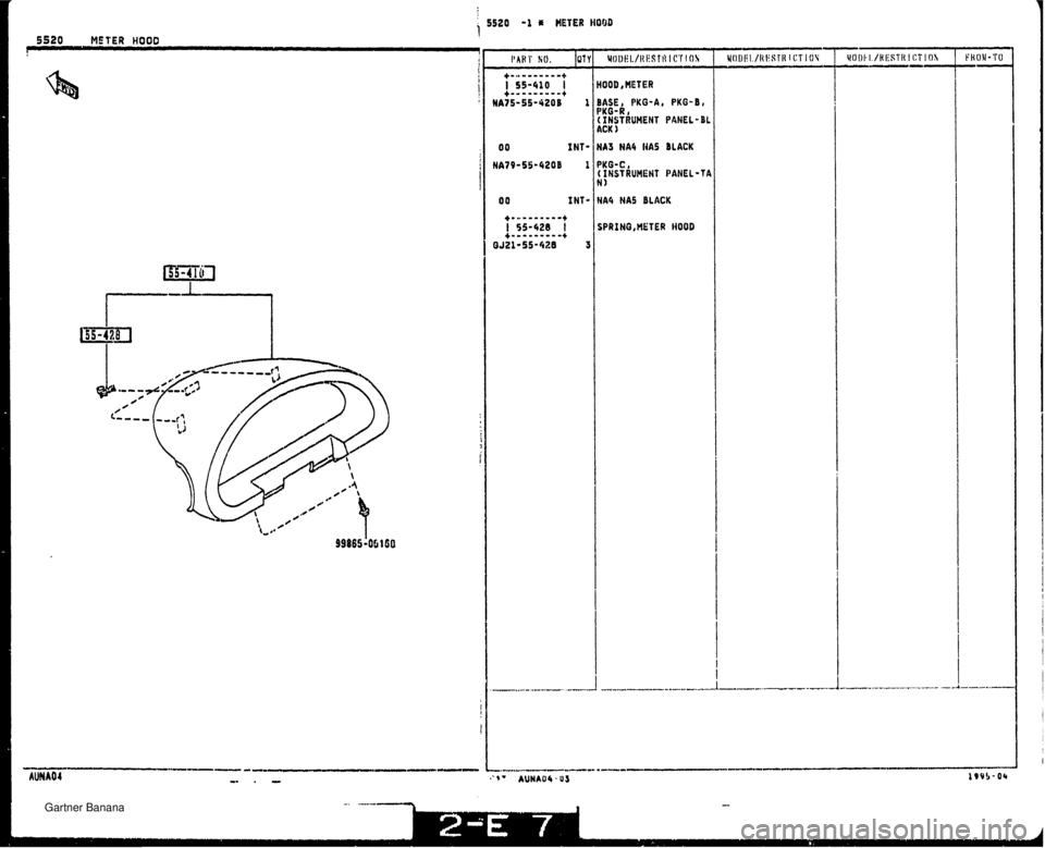
BASE, PKG-A, PKG-8, PKG-R 1 ( INSTRUMENT PANEL-BL ACK 1 00 INT- NA3 NA4 NA5 BLACK I 00 INT- NA4 NAS BLACK I TER WOOD Gartner Banana
Page 1574 of 1708

i 5560 -1 DASHBOARD L RELATED PARTS I'AIJT SO. IUYI ~Ol~l!l./~!l~~TR lf!T I GI 1 INT- HA3 NA5 NAI HA6 I BLACK HA75-60-350P A 00 INT- NAI HA6 Ilk5 HA6 BLACK RUBBER UHETHNE BASE, PVO-A, PKG-88 PKB-R, (INSTRUMENT PANEL-BL ACI( 1 H 1 I HA6 HAS CLACK/fAH NA75-60-401C 1 BASE, PKO-A, PKG-Dl PKO-R, ( IHSTRUHEIlT PANEL-DL ACK ) HAi9-60-401C 1 ; PKO-C, ! t I#STHIJHENT PANEL-TA I 0J I#T- HA6 HAS BLACKITAN I I Gartner Banana