ABS MAZDA MX-5 1994 Workshop Manual
[x] Cancel search | Manufacturer: MAZDA, Model Year: 1994, Model line: MX-5, Model: MAZDA MX-5 1994Pages: 1708, PDF Size: 82.34 MB
Page 10 of 1708
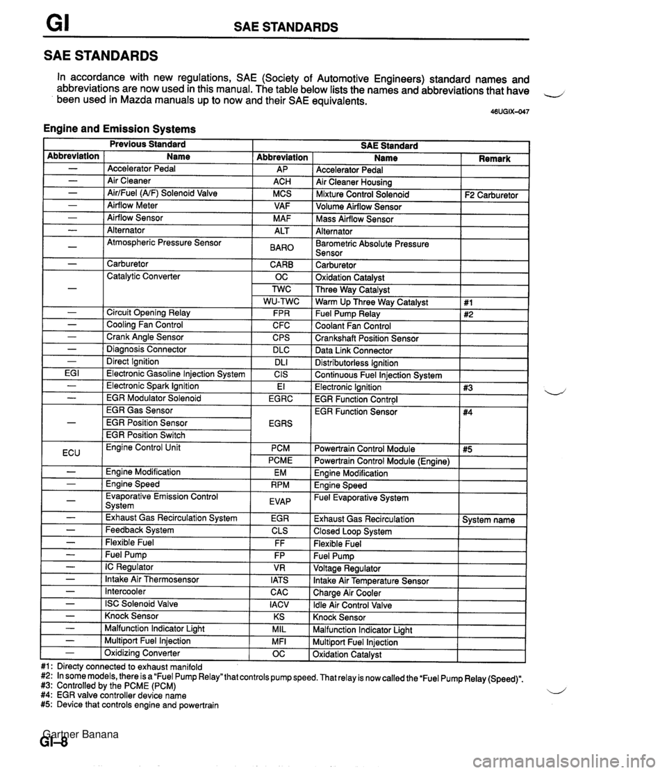
SAE STANDARDS SAE STANDARDS In accordance with new regulations, SAE (Society of Automotive Engineers) standard names and abbreviations are now used in this manual. The table below lists the names and abbreviations that have 4 been used in Mazda manuals up to now and their SAE equivalents. 46UGIX-047 Engine and Emission Systems Accelerator Pedal Air Cleaner Housing I Mixture Control Solenoid I F2 Carburetor ] Abbreviation AP ACH MCS VAF M AF Abbreviation - - - - - Volume Airflow Sensor I I Name Accelerator Pedal Air Cleaner AirlFuel (NF) Solenoid Valve Airflow Meter Airflow Sensor I Mass Airflow Sensor I I Alternator I I - - - -~ I Barometric Absolute Pressure I I Sensor I I Alternator Atmospheric Pressure Sensor I - 1 Carburetor CARB 1 Catalytic Converter OC ALT BAR0 Carburetor 1 Oxidation Catalvst I - - - - - I Direct Ignition I DL1 EG I 1 Electronic Gasoline lniection Svstem I CIS Three Way Catalyst Warm Up Three Way Catalyst Fuel Pump Relay Coolant Fan Control Crankshaft Position Sensor Data Link Connector Circuit Opening Relay Cooling Fan Control Crank Angle Sensor Diaanosis Connector Distributorless Ignition I Continuous Fuel lniection Svstem I 1 #1 #2 FPR C FC CPS DLC I Previous Standard SAE Standard Name I Remark - ( Electronic Spark Ignition EGR Gas Sensor EGR Position Sensor EGR Position Switch El Electronic Ignition 1 #3 EGR Function Control I - I EGR Modulator Solenoid I EGRC 4 ECU I Evaporative Emission Control Svstem I EVAP - - I -,--- I - I Exhaust Gas Recirculation System I EGR Engine Control Unit PCM PCME Engine Modification Ennine Speed EM RPM - - - - - Feedback System Flexible Fuel - I Intercooler Powertrain Control Module I #5 I EGR Function Sensor CLS FF Fuel Pump IC Regulator Intake Air Thermosensor CAC I Powertrain Control Module (Engine) I #4 FP VR IATS - I ISC Solenoid Valve I IACV Engine Modification I Engine Speed - Fuel Evaporative System I Exhaust Gas Recirculation 1 System name 1 Closed Loop System I Flexible Fuel Knock Sensor I I - ( Knock Sensor I KS I Malfunction Indicator Light I I - I Malfunction Indicator Liaht MIL Multiport Fuel Injection Oxidation Catalyst - 1 Multiport Fuel Injection #1: Directy connected to exhaust manifold #2: In some models, there is a "Fuel Pump Relay" that controls pump speed. That relay is now called the 'Fuel Pump Relay (Speed)". #3: Controlled by the PCME (PCM) 4 #4: EGR valve controller device name #5: Device that controls engine and powertrain MFI - 1 Oxidizina Converter OC Gartner Banana
Page 11 of 1708
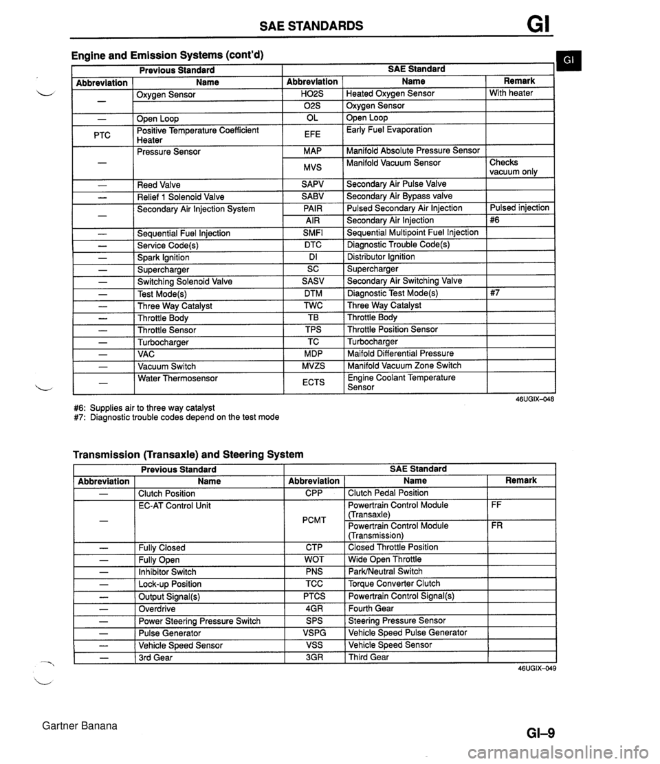
SAE STANDARDS Engine and Emission Systems (cont'd) I Previous Standard I SAE Standard b I - Abbreviation ( Name I Oxvaen Sensor - .w- - I I ." I 02s I Oxygen Sensor I - PTC Reed Valve Relief 1 Solenoid Valve Secondary Air lnjection System - Seauential Fuel lniection SMFl L - Service Code(s) DTC - Spark Ignition Dl - Supercharger SC Abbreviation I Name Open Loop Positive Temperature Coefficient Hnatar Secondarv Air Pulse Valve Remark . .--.-. Pressure Sensor Secondary Air Bypass valve Pulsed Secondarv Air lniection H02S I Heated Oxvaen Sensor I With heater OL EFE Secondary Air lnjection Sequential Multipoint Fuel lnjection Diagnostic Trouble Code(s) Open Loop Early Fuel Evaporation MAP MVS Distributor lgnition Supercharger Manifold Absolute Pressure Sensor Manifold Vacuum Sensor I - - - - - - Checks vacuum only Pulsed iniection - Switching Solenoid Valve Test Mode(s) Three Way Catalyst Throttle Body Throttle Sensor Turbocharaer .. Maifold Differential Pressure Manifold Vacuum Zone Switch , - I - 1 VAC I MDP 1-1 Water Thermosensor L - I Vacuum Switch I ECTS I Engine Coolant Temperature Sensor I SASV DTM TWC TB TPS TC MVZS #6: Supplies air to three way catalyst #7: Diagnostic trouble codes depend on the test mode - Secondary Air Switching Valve Diagnostic Test Mode(s) Three Way Catalyst Throttle Body Throttle Position Sensor Turbocharaer Transmission (Transaxle) and Steering System L - - Previous Standard I I I I Abbreviation - - - SAE Standard Fully Open Inhibitor Switch - I Lock-up Position - - Name Clutch Position EC-AT Control Unit Fullv Closed Abbreviation CPP PCMT CTP TCC I Torque Converter Clutch - - - WOT PNS Output Signal(s) Overdrive I Name Clutch Pedal Position Powertrain Control Module (Transaxle) Powertrain Control Module (Transmission) Closed Throttle Position Wide Open Throttle ParWNeutral Switch Power Steering Pressure Switch Pulse Generator Vehicle Speed Sensor - 1 3rd Gear Remark FF FR PTCS 4GR 3GR I Third Gear Powertrain Control Signal(@ Fourth Gear SPS VSPG VSS Steering Pressure Sensor Vehicle Speed Pulse Generator Vehicle Speed Sensor Gartner Banana
Page 158 of 1708
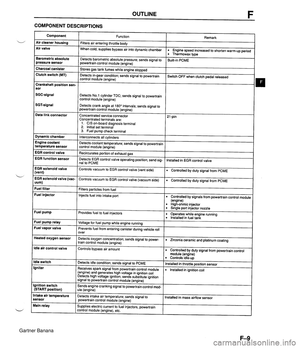
OUTLINE F COMPONENT DESCRIPTIONS Component Air cleaner housing Air valve Remark Function Filters air entering throttle body When cold, supplies bypass air into dynamicchamber w Engine speed increased to shorten warm-up period Thermowax type Barometric absolute pressure sensor Detects barometric absolute pressure; sends signal to powertrain control module (engine) 3uilt-in PCME Charcoal canister Clutch switch (MT) Stores gas tank fumes while engine stopped Detects in-gear condition: sends signal to powertrain control module (engine) --- ~witch OFF when clutch pedal released Crankshaft position sen- sor Detects No.1 cylinder TDC; sends signal to powertrain control module (engine) Detects crank angle at 180" intervals; sends signal to powertrain control module (engine) Data link connector Concentrated service connector Concentrated terminals are: 1. CIS on-board diagnosis terminal 2. Initial set terminal 3. Fuel pump check terminal Dynamic chamber Interconnects all cylinders Detects coolant temperature; sends signal to powertrain control module (engine) Recircurates oortion of exhaust aas Engine coolant temperature sensor EGR control valve lnstalled in EGR control valve EGR function sensor Detects EGR control valve operating position; send sig- nal to PCME EGR solenoid valve (vent) Controls vacuum to EGR control valve (vent side) Controlled by duty signal from PCME . - EGR solenoid valve (vac- Controls vacuum to EGR control valve (vacuum side) 0 Controlled by duty signal from PCME uum) Fuel filter Filters particles from fuel Injects fuel into intake port Fuel injector Controlled by signals from powertrain control module (engine) High-ohmic injector 0 Sinale port injector nozzle Fuel pump Provides fuel to fuel injectors 0 operates while engine running lnstalled in fuel tank Fuel pump relay Voltage for fuel pump while engine running Fuel vapor valve Prevents fuel from entering canister during vehicle roll over Heated oxygen sensor Detects oxygen concentration; sends signal to power- train control module (engine) 0 Zirconia ceramic and platinum coating ldle air control valve Controls bypass air amount Controlled by duty signal from powertrain control module (engine) Controls idle-up lnstalled in throttle position sensor lnstalled in ignition coil ldle switch Igniter Detects idle condition; sends signal to PCME Receives spark signal from powertrain control module (engine) and generates high voltage in ignition coil Detects high voltage ignition; sends substitute ignition signal to powertrain control module (engine) Ignition switch (START position) Sends engine cranking signal to powertrain control mod- ule (engine) Intake air temperature sensor Detects intake air temperature: sends signal to powertrain control module (engine) Installed in mass airflow sensor Main relay Supplies electric current to fuel injectors, powertrain control module (engine), etc. Gartner Banana
Page 159 of 1708
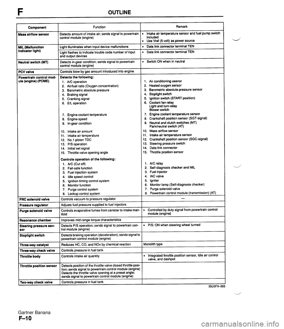
Neutral swltch (MT) 7 PCV valve Powertrain control mod- ule (engine) (PCME) Purge solenoid valve Resonance chamber Steering pressure sen- Stoplight swltch I Throttle posltion sensor r [Two-way check valve Function jetects amount of intake air; sends signal to powertrain :ontrol module (engine) Li~ht illuminates when input device malfunctions - Light flashes to indicate trouble code number of input and output devices Detects in-gear condition; sends signal to powertrain :ontrol module (engine) - Controls blow by aas amount introduced into engine Detects the followlng: 1. A/C operation 2. Airlfuel ratio (Oxygen concentration) 3. Barometric absolute pressure 4. Braking signal 5. Cranking signal 6. EIL operation 7. Engine coolant temperature 8. Engine speed 9. In-gear condition 10. lntake air amount 11, lntake air temperature 12. No.1 piston TDC 13. PIS operation 14. Initial set signal 15. Throttle valve opening angle Controls operatlon of the followlng: 1. AIC (Cut off) 2. Fail-safe function 3. Fuel injection system 4. ldle speed control 5. Ignition timing control system 6. Monitor function 7. Purge control system 8. Lockup control svstem Controls vacuum to pressure regulator -- Adjusts fuel pressure supplied to fuel injectors Controls evaporative fumes from canister to intake man- ifold -- lm~roves mid-ranae torque characteristics -. Detects PIS operation; sends signal to powertrain con- trol module (engine) -- Detects braking operation (deceleration); sends signal to powertrain control module (engine) Reduces HC, CO, and NOx by chemical reaction Controls pressurein fuel tank Controls intake air quantity Detects position of the throttle valve closed throttle posi- tion; sends signal to powertrain control module (engine) Detects the throttle valve opening at a preset angle; sends si~nal to powertrain control module (engine) controls pressure in fuel tank Remark lntake air temperature sensor and fuel pump switch included Use Vref (5 volt) as power source ' Data link connector terminal TEN ' Data link connector terminal TEN Switch ON when in neutral 1, Air conditioning sesnor 2. Heated oxygen sensor 3. Barometric absolute pressure sensor 4. Stoplight switch 5. Ignition switch (START position) 6. Coolant fan relay Light and turn relay Blower switch 7. Engine coolant temperature sensor 8. Crankshaft position sensor (SGT-signal) 9. Neutral and dutch switches (MT) Parklneutral switch (AT) 10. Mass airflow sensor 11, lntake air temperature sensor 12. Crankshaft position sensor (SGC-signal) 13. Steering pressure switch 14. Data link connector 15. Throttle position sensor 1. NC relay 2. Self-diagnosis checker and MIL 3. Fuel injector 4. IAC valve 5. Igniter 6. Monitor lamp (Self-diagnosis checker) 7. Purge solenoid valve 8. Powertrain control module (transmission) (AT) D Controlled by duty signal from powertrain control module (engine) D PIS: ON when steering wheel turned Monolith type D Integrated throttle position sensor, Idle air control valve, and dashpol Gartner Banana
Page 161 of 1708

TROUBLESHOOTING GUIDE RELATIONSHIP CHART Fuel injector TEN Terminal (Data link connector) Ignition Switch (Start Position) Steering Pressure Sensor X X X X X X X X X X X X X X X xoo Blower Switch Headlight Switch Stoplight Switch Neutral and Clutch Switches (MT) Parklneutral switch (AT) Air Conditioning Sensor Idle Switch Throttle I BDL) Position Sensor I Sensor (NO) Barometric Absolute Pres- sure Sensor IGF Signal Heated Oxygen Sensor Engine Coolant Temperature Sensor Sensor Mass Air- flow Sensor Intake Air Temperature Sensor Crankshaft SGTSignal Position Sensor SGC-Signal Gartner Banana
Page 230 of 1708
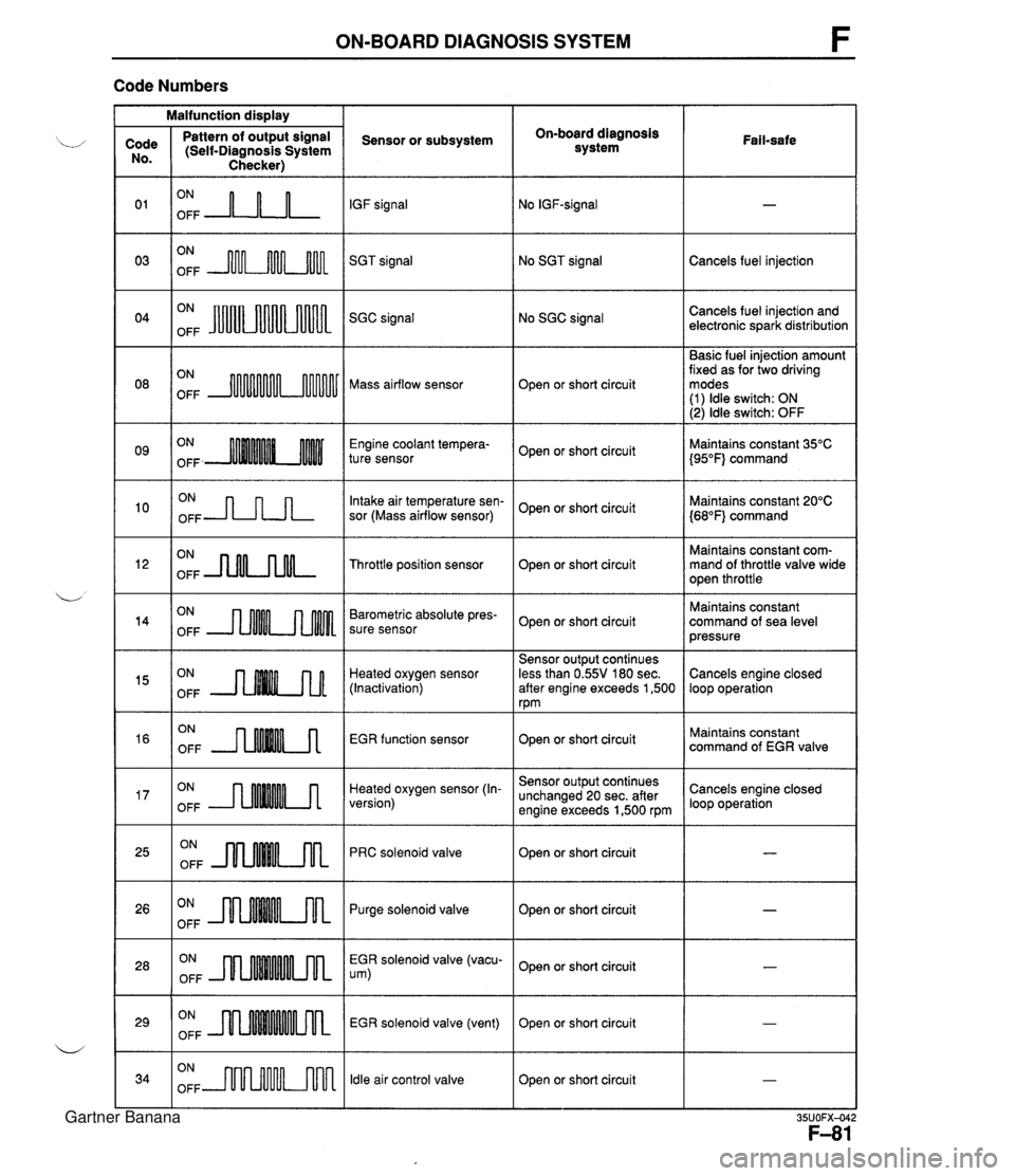
ON-BOARD DIAGNOSIS SYSTEM F Code Numbers Malfunction display On-board diagnosis system Code No. 0 1 03 Pattern of output signal (Self-Diagnosis System Checker) Sensor or subsystem IGF signal SGT signal Fail-safe ON OFF A-n-L ON OFF m No SGT signal ON OFF JuUu Cancels fuel injection No SGC signal Cancels fuel injection and electronic spark distribution SGC signal Basic fuel injection amount fixed as for two driving modes (1) ldle switch: ON (2) ldle switch: OFF ON OFF Mass airflow sensor Open or short circuit Engine coolant tempera- ture sensor ON OFF -JLnn Open or short circuit Intake air temperature sen- sor (Mass airflow sensor) Maintains constant 35°C {95"F} command Maintains constant 20°C {68"F} command Open or short circuit ON OFF -nNLnM- Maintains constant com- mand of throttle valve wide open throttle Throttle position sensor Open or short circuit ON OFF Barometric absolute pres- sure sensor Maintains constant command of sea level pressure Open or short circuit Heated oxygen sensor (Inactivation) EGR function sensor Sensor output continues less than 0.55V 180 sec. after engine exceeds 1,500 rpm Cancels engine closed loop operation ON OFF ON OFF --nMM.A ON OFF --rMMMA Open or short circuit Heated oxygen sensor (In- version) Maintains constant command of EGR valve ON OFF JlnMkm Sensor output continues unchanged 20 sec. after engine exceeds 1,500 rpm PRC solenoid valve Cancels engine closed loop operation Open or short circuit Open or short circuit I - ON OFF m Purge solenoid valve ON OFF EGR solenoid valve (vacu- um) ON OFF Open or short circuit EGR solenoid valve (vent) ldle air control valve - Open or short circuit ON OFF m Open or short circuit I - Gartner Banana
Page 236 of 1708
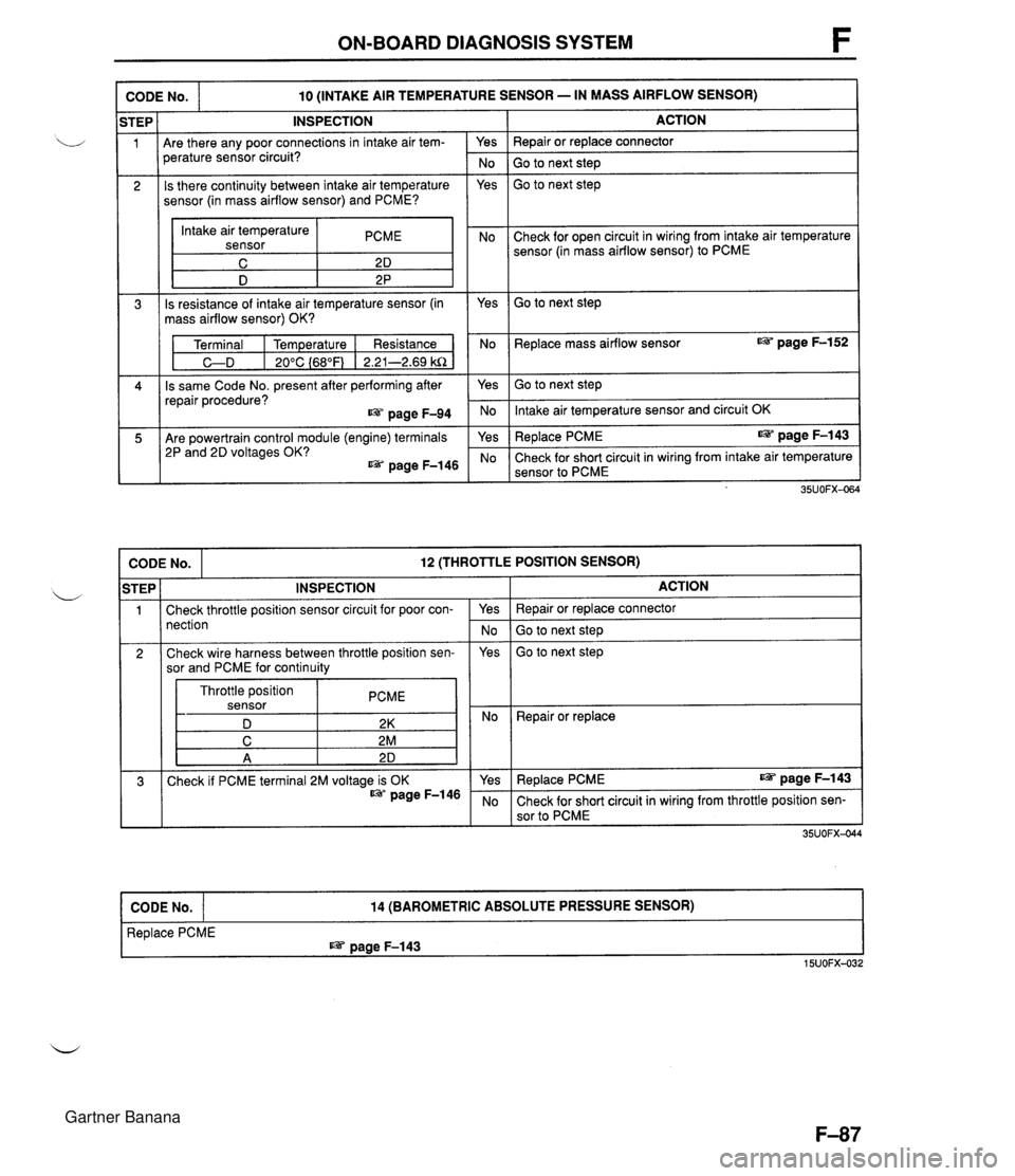
ON-BOARD DIAGNOSIS SYSTEM I CODE No. I -- -- 10 (INTAKE AIR TEMPERATURE SENSOR - IN MASS AIRFLOW SENSOR) INSPECTION Are there any poor connections in intake air tem- Yes perature sensor circuit? No Is there continuity between intake air temperature Yes sensor (in mass airflow sensor) and PCME? Intake air temperature sensor PCME I D 2 P Is resistance of intake air temperature sensor (in Yes mass airflow sensor) OK? Terminal I Temperature I Resistance No C-D I 20°C {68"F) 1 2.21-2.69 kR Is same Code No. present after performing after Yes repair procedure? page F-94 No Are powertrain control module (engine) terminals 2P and 2D voltages OK? @= page F-146 ACTION Repair or replace connector Go to next step Go to next step Check for open circuit in wiring from intake air temperature sensor (in mass airflow sensor) to PCME Go to next step Replace mass airflow sensor @= page F-152 -- Go to next step Intake air temperature sensor and circuit OK Replace PCME IS= page F-143 Check for short circuit in wiring from intake air temperature sensor to PCME CODE No. 12 (THROTTLE POSITION SENSOR) I Check throttle position sensor circuit for poor con- nection Throttle position sensor PCME D 2K 2 Repair or replace STEP 1 INSPECTION Yes No ACTION Repair or replace connector Go to next step Check wire harness between throttle position sen- sor and PCME for continuity 3 Replace PCME IS= page F-143 15UOFX-032 Yes CODE No. Go to next step 35UOFX-04 Check if PCME terminal 2M voltage is OK page F-146 14 (BAROMETRIC ABSOLUTE PRESSURE SENSOR) Yes No Replace PCME I@= page F-143 Check for short circuit in wiring from throttle position sen- sor to PCME Gartner Banana
Page 252 of 1708
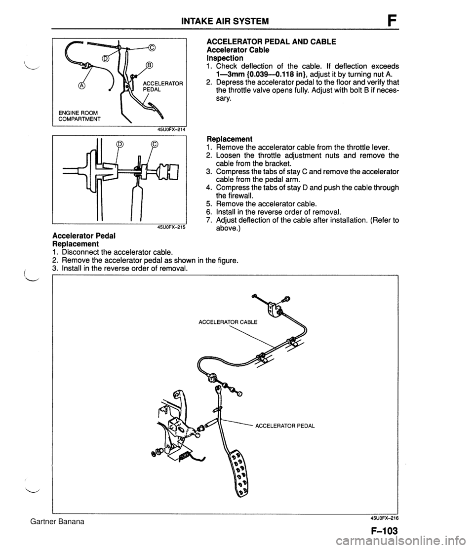
INTAKE AIR SYSTEM ENGINE ROOM COMPARTMENT 'OR ACCELERATOR PEDAL AND CABLE Accelerator Cable Inspection 1. Check deflection of the cable. If deflection exceeds 1-3mm (0.039-0.118 in), adjust it by turning nut A. 2. Depress the accelerator pedal to the floor and verify that the throttle valve opens fully. Adjust with bolt B if neces- sary. Replacement 1. Remove the accelerator cable from the throttle lever. 2. Loosen the throttle adjustment nuts and remove the cable from the bracket. 3. Compress the tabs of stay C and remove the accelerator cable from the pedal arm. 4. Compress the tabs of stay D and push the cable through the firewall. 5. Remove the accelerator cable. 6. Install in the reverse order of removal. 7. Adiust deflection of the cable after installation. (Refer to I 45~0~~-215 adbve.) Accelerator Pedal Replacement 1. Disconnect the accelerator cable. 2. Remove the accelerator pedal as shown in the figure. 3. Install in the reverse order of removal. ACCELERATOR PEDAL Gartner Banana
Page 280 of 1708

FUEL EVAPORATIVE SYSTEM FUEL EVAPORATIVE SYSTEM DESCRIPTION The fuel evaporative system consists of the fuel vapor valve, the two-way check valve, the charcoal can- ister, the purge solenoid valve, the powertrain control module (engine), and the input devices. The amount of evaporative fumes introduced into the engine and burned is controlled by the solenoid valve in relation to the engine's operating conditions. To maintain the best engine performance, the solenoid valve is controlled by the powertrab control module (engine). THROTTLE 1-1 POSITION SENSOR I1 I I (IDLE SWITCH) 7 BAROMETIC ABSOLUTE PRESSURE SENSOR PARWNEUTRAL SWITCH (AT) MASS AIRFLOW SENSOR CRANKSHAFT POSITION SENSOR (SGT-SIGNAL) n - DUTY - LOW HIGH (ENGINE) CHARCOAL PURGE SOLENOID VALVE CANISTER HEATED OXYGEN SENSOR ENGINE COOLANT POWERTRAIN TEMPERATURE SENSOR CONTROL MODULE CHECK VALVE # 11 FUEL VAPOR VALVE Operation The purge solenoid valve is controlled by duty signals from the powertrain control module (engine) to per- form purging of the charcoal canister. Purging is done when these conditions are met: i/ 1. After warm-up. 2. Driving in gear. 3. Accelerator pedal depressed (idle switch OFF). 4. Heated oxygen sensor functioning normally. Gartner Banana
Page 371 of 1708

TRANSMISSION 1. Snap ring 2. Washer 3. Retaining ring b 4. C-washer 5. Mainshaft rear bearing Disassembly Note . below Inspection ... page J-25 6. Retaining ring 7. C-washer 8. Thrust lock washer 9. Steel ball 10. Locknut (Countershaft) Disassembly Note ................ below 11. Countershaft rear bearing Disassembly Note ........... page J-18 Inspection ... page J-25 12. Counter 5th gear Inspection ... page J-23 13. Spacer 14. 5th gear 15. 5th synchronizer ring Inspection ... page J-24 16. Locknut (Mainshaft) Disassembly Note ........... page J-18 17. Clutch hub assembly (5thIReverse) Inspection ... page J-23 18. Reverse synchronizer ring Inspection ... page J-24 19. Reverse gear Inspection ... page J-23 20. Bearing Inspection ... page J-25 21. Bearing race 22. Washer 23. Counter reverse gear Inspection ... page J-23 24. Main drive gear bearing Disassembly Note ........... page J-18 Inspection ... page J-25 26. Countershaft front bearing Disassembly Note ........... page J-18 Inspection ... page J-25 27. Bearing housing assembly Disassembly Note ........... page J-18 Disassembly page J-20 28. Mainshaft gear assembly 29. Main drive gear Inspection ... page J-23 30. 4th synchronizer ring Inspection ... page J-24 31. Bearing Inspection ... page J-25 32. Washer 33. Countershaft Inspection ... page J-23 34. Spacer 35. Synchronizer key springs 36. Clutch hub sleeve 37. Synchronizer key . . Inspection ... page J-23 25. Snap ring 38. Clutch hub 45UOJX-012 Disassembly note Mainshaft rear bearing Remove the mainshaft rear bearing by using the SST. Locknut (Countershaft) 1. Shift the clutch hub sleeves into 1 st and Reverse gears to lock the rotation of the mainshaft. 2. Use a suitable tool to uncrimp the tabs of the locknut. 3. Connect the SST to the mainshaft and secure it in a vise. 4. Remove the locknut. Gartner Banana