automatic transmission fluid MAZDA MX-5 1994 Workshop Manual
[x] Cancel search | Manufacturer: MAZDA, Model Year: 1994, Model line: MX-5, Model: MAZDA MX-5 1994Pages: 1708, PDF Size: 82.34 MB
Page 7 of 1708

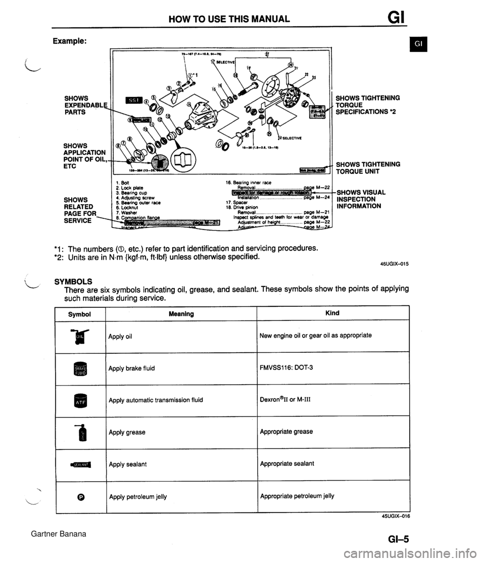
HOW TO USE THIS MANUAL Example: SHOWS EXPENDABLE PARTS SHOWS APPLICATION POINT OF OIL, ETC SHOWS RELATED PAGE FOR. SERVICE SELECTIVE 1. 8011 2. Lock plate 3. Bearing cup t. Adjusting screw 5. Bearing outer race 5. Locknul 16. Bearing inner race 18. drive pinion 1. Washer Removal ..................... .. .... page M-2' SHOWS TIGHTENING TORQUE SPECIFICATIONS *2 SHOWS TIGHTENING TORQUE UNIT -SHOWS VISUAL INSPECTION INFORMATION *1: The numbers (0, etc.) refer to part identification and servicing procedures. *2: Units are in N.m {kgf.m, ftlbf} unless otherwise specified. $ L SYMBOLS There are six symbols indicating oil, grease, and sealant. These symbols show the points of applying such materials during service. Symbol I Meaning ~pp~y oil Apply brake fluid I Apply automatic transmission fluid Apply grease Apply sealant Kind 0 New engine oil or gear oil as appropriate Apply petroleum jelly Appropriate grease Appropriate sealant Appropriate petroleum jelly Gartner Banana
Page 9 of 1708

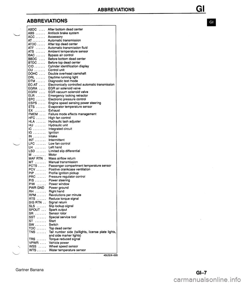
ABBREVIATIONS 4BDC .... 4BS ...... 4CC ...... 4T ........ 4TDC ..... 4TF ...... 4TS ...... 3AC ...... 3BDC .... 3TDC ..... :ID ....... 2U ....... IOHC .... IRL ...... ITM ...... IC-AT .... iGRA .... EGRV .... ELR ...... EPC ...... ESPS ..... ETS ...... EX ....... FMEM .... HFC ...... HLA ...... H U ....... IC ........ IG ........ IN ........ INT ....... LFC ...... LH ....... LSD ...... M ........ MAF RTN . MT ....... PCTS ..... PCV ...... PIP ....... PRC ...... PIS ....... PMI ...... PWR GND RH ....... RPM ...... RTS ...... SIG RTN . . SLS ...... ... SPOUT S R ....... SST ...... ST ....... SW ....... TDC ...... TNS ...... TRS ...... VPWR .... WSS ..... WTS...... After bottom dead center Antilock brake system Accessory Automatic transmission After top dead center Automatic transmission fluid Ambient temperature sensor Bypass air control Before bottom dead center Before top dead center Cylinder identification display Control unit Double overhead camshaft Daytime running light Diagnostic test mode Electronically controlled automatic transmission EGR air solenoid valve EGR vacuum solenoid valve Emergency locking retractor Electronic pressure control Engine speed sensing power steering Evaporator temperature sensor Exhaust Failure mode effects management High fan control Hydraulic lash adjuster Hydraulic unit Integrated circuit Ignition Intake Intermittent Low fan control Left hand Limited slip differential Motor Mass airflow return Manual transmission Passenger compartment temperature sensor Positive crankcase ventilation Profile ignition pickup Pressure regulator control Power steering Power window Power ground Right hand Revolutions per minute Reduce torque signal Signal return Slip lockup signal Spark output Sensor rotor Special service tool Start Switch Top dead center Tail number side (taillights, license plate lights and side marker lights) Torque reduced signal Vehicle power Wheel speed sensor Water temperature sensor Gartner Banana
Page 23 of 1708

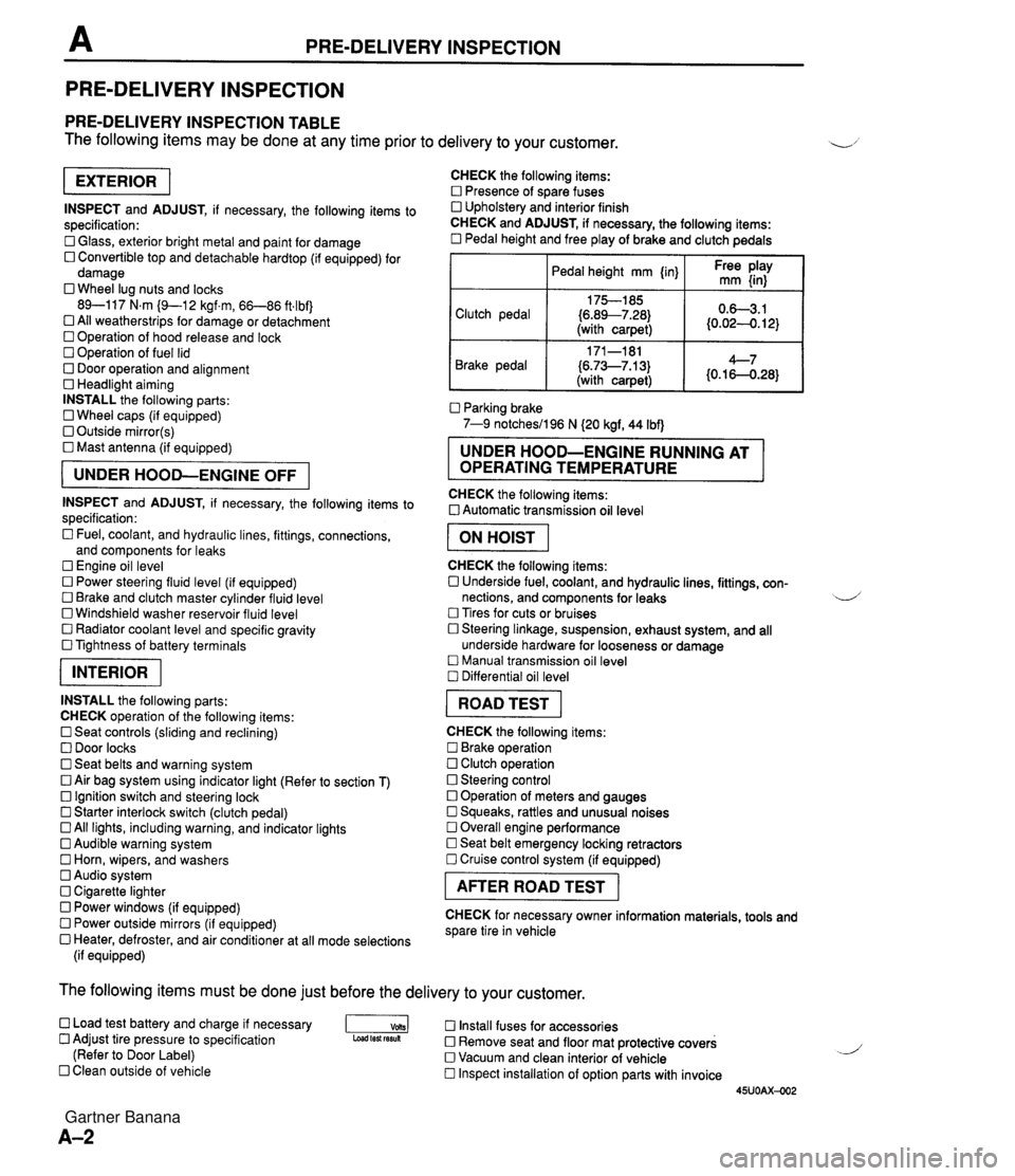
PRE-DELIVERY INSPECTION PRE-DELIVERY INSPECTION PRE-DELIVERY INSPECTION TABLE The following items may be done at any time prior to delivery to your customer. INSPECT and ADJUST, if necessary, the following items to specification: 0 Glass, exterior bright metal and paint for damage 0 Convertible top and detachable hardtop (if equipped) for damage 0 Wheel lug nuts and locks 89-117 N.m (9-1 2 kgf.m, 66-86 ft4bf) 0 All weatherstrips for damage or detachment Operation of hood release and lock Operation of fuel lid 0 Door operation and alignment Headlight aiming INSTALL the following parts: Wheel caps (if equipped) 0 Outside mirror(s) 0 Mast antenna (if equipped) UNDER HOOD-ENGINE OFF INSPECT and ADJUST, if necessary, the following items to specification : Fuel, coolant, and hydraulic lines, fittings, connections, and components for leaks Engine oil level 0 Power steering fluid level (if equipped) Brake and clutch master cylinder fluid level 0 Windshield washer reservoir fluid level 0 Radiator coolant level and specific gravity 0 Tightness of battery terminals pKiq INSTALL the following parts: CHECK operation of the following items: 0 Seat controls (sliding and reclining) 0 Door locks 0 Seat belts and warning system 0 Air bag system using indicator light (Refer to section T) Ignition switch and steering lock 0 Starter interlock switch (clutch pedal) All lights, including warning, and indicator lights 0 Audible warning system 0 Horn, wipers, and washers Audio system 0 Cigarette lighter Power windows (if equipped) 0 Power outside mirrors (if equipped) 0 Heater, defroster, and air conditioner at all mode selections (if equipped) CHECK the following items: Presence of spare fuses 0 Upholstery and interior finish CHECK and ADJUST, if necessary, the following items: 0 Pedal height and free play of brake and clutch pedals I Pedal height mm {in} I Ft: $iy I Clutch pedal {6.89--7.28) (with carpet) Parking brake 7-9 notchesil96 N (20 kgf, 44 Ibf) 0.63.1 (0.024. 12) Brake pedal RUNNING AT OPERATING TEMPERATURE CHECK the following items: 0 Automatic transmission oil level 171-181 (6.73--7.13) (with carpet) I ON HOIST I 4--7 {0.16-0.28} CHECK the following items: 0 Underside fuel, coolant, and hydraulic lines, fittings, con- nections, and components for leaks 4 Tires for cuts or bruises 0 Steering linkage, suspension, exhaust system, and all underside hardware for looseness or damage Manual transmission oil level Differential oil level I ROAD TEST I CHECK the following items: Brake operation Clutch operation 0 Steering control 0 Operation of meters and gauges Squeaks, rattles and unusual noises 0 Overall engine performance Seat belt emergency locking retractors 0 Cruise control system (if equipped) I AFTER ROAD TEST I CHECK for necessary owner information materials, tools and spare tire in vehicle The following items must be done just before the delivery to your customer. 0 Load test battery and charge if necessary -1 Install fuses for accessories Adjust tire pressure to specification Load test fesuk 0 Remove seat and floor mat protective covers (Refer to Door Label) 0 Vacuum and clean interior of vehicle Clean outside of vehicle Inspect installation of option parts with invoice 45UOAX-002 Gartner Banana
Page 402 of 1708

Before beginning any service procedure. refer to section T of this manual for air bag system service warnings and audio antitheft system alarm conditions . AUTOMATIC TRANSMISSION INDEX ................................ K- 2 OUTLINE ............................. K- 3 SPECIFICATIONS ................... K- 3 ........... CROSS-SECTIONAL VIEW K- 4 POWER FLOW DIAGRAM ............ K- 5 OPERATION OF COMPONENTS ...... K- 5 FLUID PASSAGE LOCATIONS ........ K- 6 TROUBLESHOOTING .................. K- 8 GENERAL NOTES ................... K- 8 .......... QUICK DIAGNOSIS CHART K- 9 ON-BOARD DIAGNOSIS SYSTEM ...... K- 11 DESCRIPTION ...................... K- 11 PREPARATION ...................... K- 11 ....... DIAGNOSTIC TROUBLE CODE K- 11 .......... MECHANICAL SYSTEM TEST K- 22 PREPARATION ...................... K- 22 STALL TEST ........................ K- 22 TIME LAG TEST ..................... K- 25 LINE PRESSURE TEST .............. K- 26 ROAD TEST .......................... K- 29 D-RANGE TEST ..................... K- 29 S-RANGE TEST ..................... K- 31 ..................... L-RANGE TEST K- 32 . P-RANGE TEST ..................... K- 33 AUTOMATIC TRANSMISSION FLUID (ATF) ................................ K- 35 ATF ................................ K- 35 REPLACEMENT ..................... K- 37 ELECTRICAL SYSTEM COMPONENTS . . K- 38 PREPARATION ...................... K- 38 HOLD SWITCH ...................... K- 38 PARWNEUTRAL SWITCH ............ K- 39 .............. ATF THERMOSENSOR K- 41 VEHICLE SPEED PULSE GENERATOR ...................... K- 41 1-2 SHIFT. 2-3 SHIFT. 3-4 SHIFT. ... 3-2 CONTROL SOLENOID VALVE K- 42 LOCKUP CONTROL SOLENOID ....... VALVE ............................ K- 42 POWERTRAIN CONTROL MODULE (TRANSMISSION) .................. K- 43 TRANSMISSION ....................... K- 46 TRANSMISSION UNIT (REMOVAL) .... K- 46 TRANSMISSION UNlT (DISASSEMBLY) ................... K- 50 TORQUE CONVERTER .............. K- 61 OILPUMP .......................... K- 62 FOURTH GEAR CONNECTING SHELL AND FOURTH GEAR PLANETARY GEAR UNIT (FOURTH GEAR SUN GEAR. FOURTH GEAR PLANETARY PINION CARRIER. FOURTH GEAR CLUTCH HUB) ...... K- 67 DIRECT CLUTCH .................... K- 70 FOURTH GEAR BAND SERVO ........ K- 76 DRUM SUPPORT. ACCUMULATOR. AND FOURTH GEAR CASE ......... K- 79 2ND BAND SERVO .................. K- 83 FRONT CLUTCH .................... K- 86 REAR CLUTCH ...................... K- 91 CONNECTING SHELL AND FRONT PLANETARY GEAR UNlT (REAR CLUTCH HUB. FRONT PLANETARY PINION CARRIER. REAR SUN GEAR) ................. K- 96 REAR PLANETARY GEAR UNlT (CONNECTING DRUM. REAR PLANETARY PINION CARRIER. ONE-WAY CLUTCH) K- 98 LOW AND REVERSE BRAKE K-102 ................ ......... EXTENSION HOUSING AND PARKING MECHANISM ............. K-107 OIL SEAL ........................... K-ill CONTROL VALVE BODY ............. K-112 UPPER VALVE BODY ................ K-116 LOWER VALVE BODY ............... K-120 CONTROL VALVE BODY ............. K-125 VACUUM DIAPHRAGM ............... K-130 TRANSMISSION UNIT (ASSEMBLY) ... K-132 TRANSMISSION UNIT (INSTALLATION) ................... K-147 OIL COOLER .......................... K-151 REMOVAL I INSPECTION I INSTALLATION ..................... K-151 DRIVE PLATE ......................... K-152 PREPARATION ...................... K-152 REMOVAL 1 INSPECTION I INSTALLATION ..................... K-152 SHIFT MECHANISM (WITH SHIFT-LOCK SYSTEM) ......... K-154 SHIFT-LOCK SYSTEM COMPONENTS K-154 TROUBLESHOOTING ................ K-155 SHIFT-LOCK ........................ K-157 EMERGENCY OVERRIDE BUTTON ... K-157 KEY INTERLOCK .................... K-157 KEY INTERLOCK SOLENOID ......... K-157 KEY INTERLOCK UNIT ............... K-158 P RANGE SWITCH .................. K-159 SHIFT-LOCKACTUATOR ............. K-159 SELECTOR LEVER .................. K-161 HYDRAULIC CIRCUIT .................. K-168 P RANGE ........................... K-168 R RANGE ........................... K-169 N RANGE; BELOW 7 kmlh I4.34 mph) . K-170 N RANGE; ABOVE 9 kmlh (5.58 mph} . K-171 D RANGE; 1 ST GEAR ................ K-172 D RANGE; 2ND GEAR ............... K-173 D RANGE; THIRD GEAR ............. K-174 D RANGE; FOURTH GEAR. LOCKUP ON ....................... K-175 S RANGE; 1 ST GEAR ................ K-176 S RANGE; 2ND GEAR ............... K-177 S RANGE; THIRD GEAR ............. K-178 L RANGE; 1 ST GEAR ................ K-179 L RANGE; 2ND GEAR ................ K-180 Gartner Banana
Page 404 of 1708

INDEX, OUTLINE K 1. Hold switch lnspection . . . . . . . . . . . . . . . . page K- 38 Replacement . . . . . . . . . . . . . page K- 39 b 2. ParkINeutral switch lnspection . . . . . . . . . . . . . . . . page K- 39 Adjustment . . . . . . . . . . . . . . . page K- 40 3. Vehicle speed pulse generator lnspection . . . . . . . . . . . . . . . . page K- 41 Replacement . . . . . . . . . . . . . page K- 42 4. ATF thermosensor lnspection . . . . . . . . . . . . . . . . page K- 41 Replacement . . . . . . . . . . . . . page K- 41 5. 1-2 shift, 2-3 shift, 3-4 shift, 3-2 control solenoid valves lnspection . . . . . . . . . . . . . . . . page K- 42 6. Lockup control solenoid valve lnspection . . . . . . . . . . . . . . . . page K- 42 7. Powertrain control module (Transmission) lnspection . . . . . . . . . . . . . . . . page K- 43 Replacement . . . . . . . . . . . . . page K- 45 OUTLINE SPECIFICATIONS 8. Automatic transmission Removal . . . . . . . . . . . . . . . . . page K- 46 Disassembly . . . . . . . . . . . . . page K- 50 Assembly . . . . . . . . . . . . . . . . page K-132 lnstallation . . . . . . . . . . . . . . . page K-147 9. Oil cooler Removal 1 Inspection / lnstallation . . . . . . . . . . . . . . page K-151 10. Drive plate Removal 1 Inspection 1 lnstallation . . . . . . . . . . . . . . page K-152 11. P range switch lnspection . . . . . . . . . . . . . . . . page K-159 12. Shift-lock actuator lnspection . . . . . . . . . . . . . . . . page K-159 13. Selector lever lnspection . . . . . . . . . . . . . . . . page K-161 Adjustment . . . . . . . . . . . . . . . page K-160 Removal / Inspection / lnstallation . . . . . . . . . . . . . . page K-163 Disassembly 1 Inspection / Assembly . . . . . . . . . . . . . . . page K-166 - Model Item - Gear ratio NC4A-EL Torque converter stall torque ratio 1 st 1.900 : 1 2.458 4GR Reverse 0.720 2.182 Number of driveldriven plates Servo diameter (Piston outer diameterketainer inner diam- eter) mm{in} Direct clutch Front clutch Rear clutch Automatic transmission fluid (Am 212 315 515 Low and reverse brake Fourth gear band servo 2nd band servo 4/4 56/36 {2.205/1.417} 72/50 {2.835/1.969} Dexron@II or M-111 7.3 {7.7,6.4} 4.0 {4.2,3.5} Type Capacity L {US qt, Imp qtI Total oil pan Gartner Banana
Page 436 of 1708

AUTOMATIC TRANSMISSION FLUID (ATF) K AUTOMATIC TRANSMISSION FLUID (ATF) ATF Inspection Level 1. Park the vehicle on level ground. 2. Apply the parking brake and position wheel chocks se- curely to prevent the vehicle from rolling. 3. Warm up the engine until the ATF reaches 60-70°C (1 40-1 58°F). 4. While depressing the brake pedal, shift the selector lever to each range (P-L), pausing momentarily in each range. 5. Shift back to P. Note In some cases it may be necessary to inspect the ATF in the cool range 15-25°C (59-77"F) before warm- ing up the engine. 6. Ensure that the ATF level is in the HOT (65°C) range. Add ATF to the specification, if necessary. ATF type: DexronQII or M-I11 Condition Determine whether the transmission should be disas- sembled by noting. 1. If the ATF is muddy or varnished. 2. If the ATF smells strange or unusual. Gartner Banana
Page 437 of 1708

K AUTOMATIC TRANSMISSION FLUID (ATF) Fluid leaks Check for fluid leaks of the transmission as shown below, and repair or replace as necessary. 1. Gaskets, O-ring, and plugs 2. Oil hoses, oil pipes, and connections 3. Oil cooler @ .... O-RING @ .... GASKET 0 .... OIL SEAL 0 .... PLUG @ .... OTHER Gartner Banana
Page 438 of 1708

AUTOMATIC TRANSMISSION FLUID (ATF) K REPLACEMENT 1. On level ground, jack up the vehicle and support it evenly on safety stands. Warning When the transmission and the ATF are hot, they can cause burns to the skin. Allow the transmis- sion and the ATF to cool before doing this proce- dure. 2. Loosen the oil pan installation bolts, and drain the ATF into a container. 3. Remove the oil pan and gasket. 4. Clean the oil pan and the magnet. 5. Install the oil pan along with a new gasket. Tightening torque: 5.9-7.8 N-m (60-80 kgfecm, 53-69 in-lbf) 6. Add approximately 4.0 L (4.2 US qt, 3.5 Imp qt} ATF, and check the ATF level. (Refer to page K-35.) Specified ATF: DexronmII or M-I11 Gartner Banana
Page 1117 of 1708

TECHNICAL DATA K. AUTOMATIC TRANSMISSION tem Transmission ;ear ratio NC4A-EL 4utomatic trans- nission fluid :ATF) 3il pump Drum support Direct clutch Forth gear plan- etary gear unit Front clutch Rear clutch Front planetary gear unit Rear planetary gear unit Low and reverse brake Oil distributor First Second Third Fourth Reverse TY pe Capacity L {US qt, Imp qt) Body clearance Standard mm {in) -Maximum Tip clearance Standard mm {in) Maximum Side clearance Standard mm {in) Maximum Seal ring and groove clear- Standard ance mm {in) Maximum Side plate clearance mm {in) Side plate size mm{in) End play mm {in) Bearing race size mm {in) Standard Pinion clearance mm {in) Maximum Total end play mm {in) Bearing race size mm (in) Retaining plate clearance mm {in) Retaining plate size mm {in) End play mm (in) Bearing race size mm {in) Retaining plate clearance mm {in) Retaining plate size mm {in) Total end play mm {in) Bearing race site mm {in) Standard Pinion clearance rnm {in) Maximum Standard Pinion clearance mm {in) Maximum Retaining plate clearance mm {in) Retaining plate size mm {in) Seal ring to groove Standard clearance mm {in) Maximum Valve spring specification 2.458 1.458 1 .OOO 0.720 2.1 82 ~exron~ll or M-Ill 7.3 {7.7, 6.4) 0.02-0.04 {0.000&0.0015) 0.08 (0.0031) 0.14--0.21 IO.0056--0.0082) 0.25 {0.0098) 0.05-0.20 {0.0020--0.0078) 0.25 {0.0098) 0.04-0.1 6 {0.0016--0.0062) - - 0.40 {0.0157) 0.2 {0.008) 0.4{0.016),0.6{0.024},0.8{0.031),1.0{0.039),1.2{0.047) 0.5-0.8 {0.020--0.031) 0.8 {0.031), 1 .O {0.039}, 1.2 (0.0471, 1.4 {0.055), 1.6 {0.063), 1.8 {0.071), 2.0 {0.079), 2.2 {0.087) 0.2-0.7 {0.008-0.028) 0.8 {0.031} 0.254.50 {0.0099-0.0196) 1.2 {0.047}, 1.4 (0.0551, 1.6 {0.063), 1.8 {0.071), 2.0 {0.079), 2.2 {0.087) 0.9-1.1 {0.036-4.043) 5.8 {0.228),6.0 (0.2361, 6.2 (0.2443, 6.4 (0.2521, 6.6 {0.260), 6.8 {0.268),7.0 {0.276) 0.5-4.8 {0.020-0.031) 0.8 {0.031), 1.0 {0.039), 1.2 {0.047), 1.4 {0.055}, 1.6 (0.063), 1.8 {0.071}, 2.0 (0.079), 2.2 (0.087) 0.-1 .O iO.032-0.039) 6.2 {O.244},6.4 {O.252}, 6.6 (0.2601, 6.8 (0.2681, 7.0 {0.276), 7.2 {0.283), 7.6 (0.299) 0.25-0.50 {0.0099--0.0196} 1.2 {0.047}, 1.4 {0.055), 1.6 {0.063), 1.8 {0.071), 2.0 {0.079}, 2.2 I0.087) 0.2-0.7 {0.008--0.027) 0.8 (0.031j 0.2-0.7 {0.00&0.027) 0.8 {0.031} 0.8-1.05 {0.031-0.041) 11.8 I0.4651, 12.0 {0.472}, 12.2 {0.480}, 12.4 {0.488}, 12.6 {0.496}, 12.8 (0.504) 0.04--0.16 (0.001 6--0.0062) 0.40 {0.0157) Control valve . . 11.7 (0.461) 7.4 (0,291 ) 10.0 (0.394) 7.5 (0.295) Pressure regulator 1-2 shift - 2-3 shift 3-4 shift Wire dia. mm fin) Outer dia. mm fin) . . 43.0 (1.693) 26.4 (1 .039) 50.0 (1.969) 40.2 (1.563) Free length mm (in of coils 13.0 9.6 13.7 15.0 -. 1.2 (0.047) 0.7 (0.026) 1 .O (0.039) 0.8 (0.031 ) Gartner Banana