air conditioning MAZDA MX-5 1994 Workshop Manual
[x] Cancel search | Manufacturer: MAZDA, Model Year: 1994, Model line: MX-5, Model: MAZDA MX-5 1994Pages: 1708, PDF Size: 82.34 MB
Page 12 of 1708

GI SAE STANDARDS Body Electrical System and Heater and Air Conditioner Systems Previous Standard SAE Standard - - Abbreviation I Name I Abbreviation 1 Name Remark 1 VB - - - AIC Switch Air Conditioner 46UGIX-050 #8: System name. Other related names are unchanged. Battery Voltage Coolant Level Sensor Ground Self-Diagnosis System ACS A/C B+ COLS GND OBD Air Conditioning Sensor Air Conditioner d Battery Positive Voltage Coolant Level Sensor Ground On-Board Diagnosis System #8 Gartner Banana
Page 154 of 1708
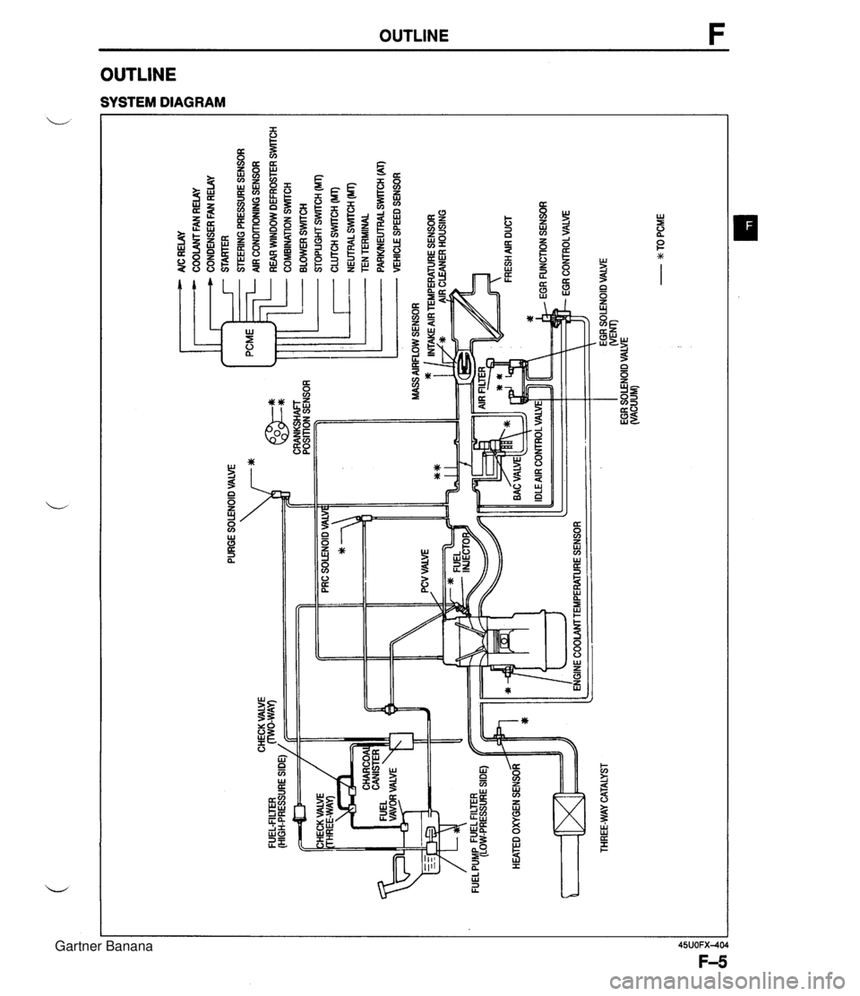
PURGE SOLENOID VALVE 7* AlC RELAY COOLANT FAN RELAY CONDENSER FAN RELAY STARTER STEERING PRESSURE SENSOR AIR CONDITIONING SENSOR ... CHECK VALVE FUEL-FILTER (HIGH-PRESSURE SIDE) / CRANKSHAFT POSITION SENSOR HEATED OXYGEN SENSOR ltT=I THREE-WAY CATALYST - REAR WINDOW DEFROSTER SWITCH COMBINATION SrmCH BLOWER SWlTCH STOPLIGHT SWITCH (MT) CLUTCH SWITCH (MT) - NEUTRALSWrrCH (MT) TEN TERMINAL PARWEUTRAL SWITCH (AT) VEHICLE SPEED SENSOR ENGINE COOLAMTEMPERATURE SENSOR EGR SOLENOID VALVE WEM) EGR SOLENOID VALVE (VACUUM) - w TO PCME Gartner Banana
Page 159 of 1708
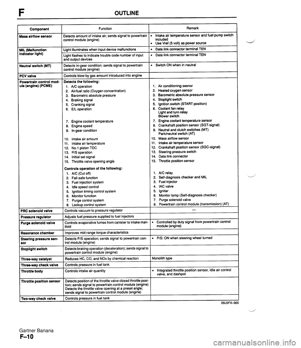
Neutral swltch (MT) 7 PCV valve Powertrain control mod- ule (engine) (PCME) Purge solenoid valve Resonance chamber Steering pressure sen- Stoplight swltch I Throttle posltion sensor r [Two-way check valve Function jetects amount of intake air; sends signal to powertrain :ontrol module (engine) Li~ht illuminates when input device malfunctions - Light flashes to indicate trouble code number of input and output devices Detects in-gear condition; sends signal to powertrain :ontrol module (engine) - Controls blow by aas amount introduced into engine Detects the followlng: 1. A/C operation 2. Airlfuel ratio (Oxygen concentration) 3. Barometric absolute pressure 4. Braking signal 5. Cranking signal 6. EIL operation 7. Engine coolant temperature 8. Engine speed 9. In-gear condition 10. lntake air amount 11, lntake air temperature 12. No.1 piston TDC 13. PIS operation 14. Initial set signal 15. Throttle valve opening angle Controls operatlon of the followlng: 1. AIC (Cut off) 2. Fail-safe function 3. Fuel injection system 4. ldle speed control 5. Ignition timing control system 6. Monitor function 7. Purge control system 8. Lockup control svstem Controls vacuum to pressure regulator -- Adjusts fuel pressure supplied to fuel injectors Controls evaporative fumes from canister to intake man- ifold -- lm~roves mid-ranae torque characteristics -. Detects PIS operation; sends signal to powertrain con- trol module (engine) -- Detects braking operation (deceleration); sends signal to powertrain control module (engine) Reduces HC, CO, and NOx by chemical reaction Controls pressurein fuel tank Controls intake air quantity Detects position of the throttle valve closed throttle posi- tion; sends signal to powertrain control module (engine) Detects the throttle valve opening at a preset angle; sends si~nal to powertrain control module (engine) controls pressure in fuel tank Remark lntake air temperature sensor and fuel pump switch included Use Vref (5 volt) as power source ' Data link connector terminal TEN ' Data link connector terminal TEN Switch ON when in neutral 1, Air conditioning sesnor 2. Heated oxygen sensor 3. Barometric absolute pressure sensor 4. Stoplight switch 5. Ignition switch (START position) 6. Coolant fan relay Light and turn relay Blower switch 7. Engine coolant temperature sensor 8. Crankshaft position sensor (SGT-signal) 9. Neutral and dutch switches (MT) Parklneutral switch (AT) 10. Mass airflow sensor 11, lntake air temperature sensor 12. Crankshaft position sensor (SGC-signal) 13. Steering pressure switch 14. Data link connector 15. Throttle position sensor 1. NC relay 2. Self-diagnosis checker and MIL 3. Fuel injector 4. IAC valve 5. Igniter 6. Monitor lamp (Self-diagnosis checker) 7. Purge solenoid valve 8. Powertrain control module (transmission) (AT) D Controlled by duty signal from powertrain control module (engine) D PIS: ON when steering wheel turned Monolith type D Integrated throttle position sensor, Idle air control valve, and dashpol Gartner Banana
Page 161 of 1708

TROUBLESHOOTING GUIDE RELATIONSHIP CHART Fuel injector TEN Terminal (Data link connector) Ignition Switch (Start Position) Steering Pressure Sensor X X X X X X X X X X X X X X X xoo Blower Switch Headlight Switch Stoplight Switch Neutral and Clutch Switches (MT) Parklneutral switch (AT) Air Conditioning Sensor Idle Switch Throttle I BDL) Position Sensor I Sensor (NO) Barometric Absolute Pres- sure Sensor IGF Signal Heated Oxygen Sensor Engine Coolant Temperature Sensor Sensor Mass Air- flow Sensor Intake Air Temperature Sensor Crankshaft SGTSignal Position Sensor SGC-Signal Gartner Banana
Page 223 of 1708
![MAZDA MX-5 1994 Workshop Manual F TROUBLESHOOTING GUIDE DESCRIPTION I Blower fan operates but cool air not expelled ITROUBLESHOOTING HINTS] Open or short circuit in wiring harness NC relay malfunction 34 Air conditioning sensor malf MAZDA MX-5 1994 Workshop Manual F TROUBLESHOOTING GUIDE DESCRIPTION I Blower fan operates but cool air not expelled ITROUBLESHOOTING HINTS] Open or short circuit in wiring harness NC relay malfunction 34 Air conditioning sensor malf](/img/28/57072/w960_57072-222.png)
F TROUBLESHOOTING GUIDE DESCRIPTION I Blower fan operates but cool air not expelled ITROUBLESHOOTING HINTS] Open or short circuit in wiring harness NC relay malfunction 34 Air conditioning sensor malfunction Magnetic clutch malfunction PCME malfunction AIC DOES NOT WORK INSPECTION ;round terminal B at NC relay with jumper wire Yes tnd check if condenser fan operates when ignition ;witch is turned ON #C RELAY I ;round terminal B at PCME 1 J terminal with jump- Yes ,r wire and check if condenser fan operates when gnition switch is turned ON - No :heck if Air conditioning sensor is OK Yes Section U ACTION 30 to next step 30 to A/C system Troubleshooting Section U 30 to next step qepair wire between PCME and A/C relay page F-7 Try known good PCME page F-144 ;heck Air conditioning sensor and wiring Section U Gartner Banana
Page 244 of 1708
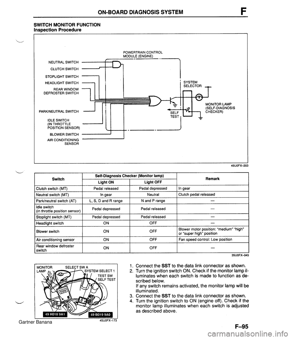
ON-BOARD DIAGNOSIS SYSTEM SWITCH MONITOR FUNCTION Inspection Procedure POWERTRAIN CONTROL MODULE (ENGINE) NEUTRAL SWITCH CLUTCH SWITCH 1 STOPLIGHT SWITCH HEADLIGHT SWITCH REAR WINDOW DEFROSTER SWITCH PARKINEUTRAL SWITCH IDLE SWITCH (IN THROTTLE POSITION SENSOR) BLOWER SWITCH AIR CONDITIONING SENSOR I ' SYSTEM MONITOR LAMP (SELF-DIAGNOSIS 1 Clutch switch (MT) 1 Pedal released I Pedal depressed I In gear I Switch Self-Diagnosis Checker (Monitor lamp) I Liaht ON Liaht OFF . . I I I - I Idle switch (in throttle position sensor) I Pedal depressed I Pedal released 1 Remark ParWneutral switch (AT) I L, S, D and R range I N and P range I I I Stoplight switch (MT) Pedal depressed I Pedal released - I Neutral I Clutch pedal released Neutral switch (MT) - In gear I I Blower switch Headlight switch OFF Blower motor position: "medium" "high" or "super hiah" position I I ON 1. Connect the SST to the data link connector as shown. 2. Turn the ignition switch ON. Check if the monitor lamp il- luminates when each switch is made to function as de- scribed below. If any switch remains activated, the monitor lamp will be illuminated. 3. Connect the SST to the data link connector as shown. 4. Turn the ignition switch to ON (engine off). Check if the monitor lamp illuminates when each switch is adjusted as described above. 45UOFX-173 OFF 1 Air conditioning sensor Rear window defroster switch - ON ON OFF OFF Fan speed control: Low position - Gartner Banana
Page 245 of 1708

F ON-BOARD DIAGNOSIS SYSTEM Procedure - Set conditions to deactivate each switch a All accessories OFF a Transmission in neutral a All pedals released Verify that monitor lamp does not illuminate Neutral and Clutch switches (MT) Parklneutral switch (AT) Depress clutch pedal Verify that monitor lamp does not illuminate Return transmission to neutral NO PC: a Neutral or clutch switch malfunction (Refer to F-146) a Open circuit in related wire harness a Powertrain control module (engine) terminal 1V malfunction (Refer to page F-146) - Shift transmission into gear Verify that monitor lamp illuminates with clutch pedal is re- leased PC: a Clutch switch malfunction (Refer to page F-157) 35UOFX-046 I ParWneutral switch OK Shift into P or N range Check each switch and related wire harness a Clutch and Neutral switch :Refer to page F-I57 a Idle switch (in throttle position sensor) :Refer to page F-154 a Stoplight switch :Refer to Section T Headlight switch :Refer to Section T 1 Check each switch as described I I NO - ldle switch (in throttle position sensor) a Blower switch :Refer to Section T a Air conditioning sensor :Refer to Section U a Rear window defroster switch :Refer to Section T a ParWneutral switch :Refer to Section K YES PC: a ParWneutral switch malfunction (Refer to Section K) a Open or short circuit in related wire harness a PCME terminal 1 V voltage incorrect (Refer to page F-I 46) PCME malfunction - Shift transmission into L, S, D, or P range Check that monitor lamp illuminates 35UOFX-06 NO + YES I 1 I ldle switch OK I L I PC: Throttle position sensor malfunction (Refer to page F-144) a Short circuit in wire harness from throttle position sensor to PCME a PCME terminal 1 N voltage incorrect (Refer to page F-145) a PCME malfunction - Depress accelerator pedal and check that monitor lamp illu- minates f NO --c YES PC: a Throttle position sensor malfunction (Refer to page F-144) Open circuit in wire harness from throttle position sensor to PCME PCME terminal 2M voltage incorrect (Refer to page F-146) Release acceleration pedal and check that monitor lamp does not illuminate 2 YES I I Gartner Banana
Page 246 of 1708

ON-BOARD DIAGNOSIS SYSTEM Stoplight switch OK Release brake pedal Stoplight switch (MT) Headlight switch PC: Stoplight switch malfunction (Refer to Section T) 0 Open circuit in wire harness from stoplight switch to powertrain control module (engine) Powertrain control module (engine) terminal 10 malfunction (Refer to page F-145) Headlight switch OK Turn OFF headlight switch I I NO ---c L, Blower switch YES Depress brake pedal and verify that monitor lamp illuminates PC: Headlight switch malfunction (Refer to section T) Open circuit in wire harness from headlight switch to powertrain control module (engine) Powertrain control module (engine) terminal 1 U malfunction (Refer to page F-146) Turn ON headlight switch Verify that monitor lamp illuminates Verify that monitor lamp illuminates NO - I YES YES Blower switch OK Turn OFF blower switch Air conditioning sensor PC: Blower switch malfunction (Refer to section T) 0 Open circuit in wire harness from blower switch to powertrain control module (engine) 0 Powertrain control module (engine) terminal IS malfunction (Refer to page F-146) 1 I YES I ' Set fan speed control to low position Turn air conditioning sensor ON, and verify that monitor lamp illuminates PC: Air conditioning sensor malfunction (Refer to Section U) Blower switch malfunction Open circuit in wire harness from air conditioning sensor to blower switch Powertrain control module (engine) terminal 1Q malfunction (Refer to page F-146) NO' 4 Air conditioning sensor OK Turn air conditioning sensor and blower switch OFF Rear window defroster switch Turn rear window defroster switch ON Is monitor lamp illuminated? NO PC: Rear window defroster switch malfunction (Refer to Section T) Open circuit in wire harness (Rear window defroster switch - PCME) PCME terminal 2L voltage incorrect (Refer to page F-146) PCME malfunction YES Turn rear window defroster switch OFF u Rear window defroster switch OK Gartner Banana
Page 285 of 1708
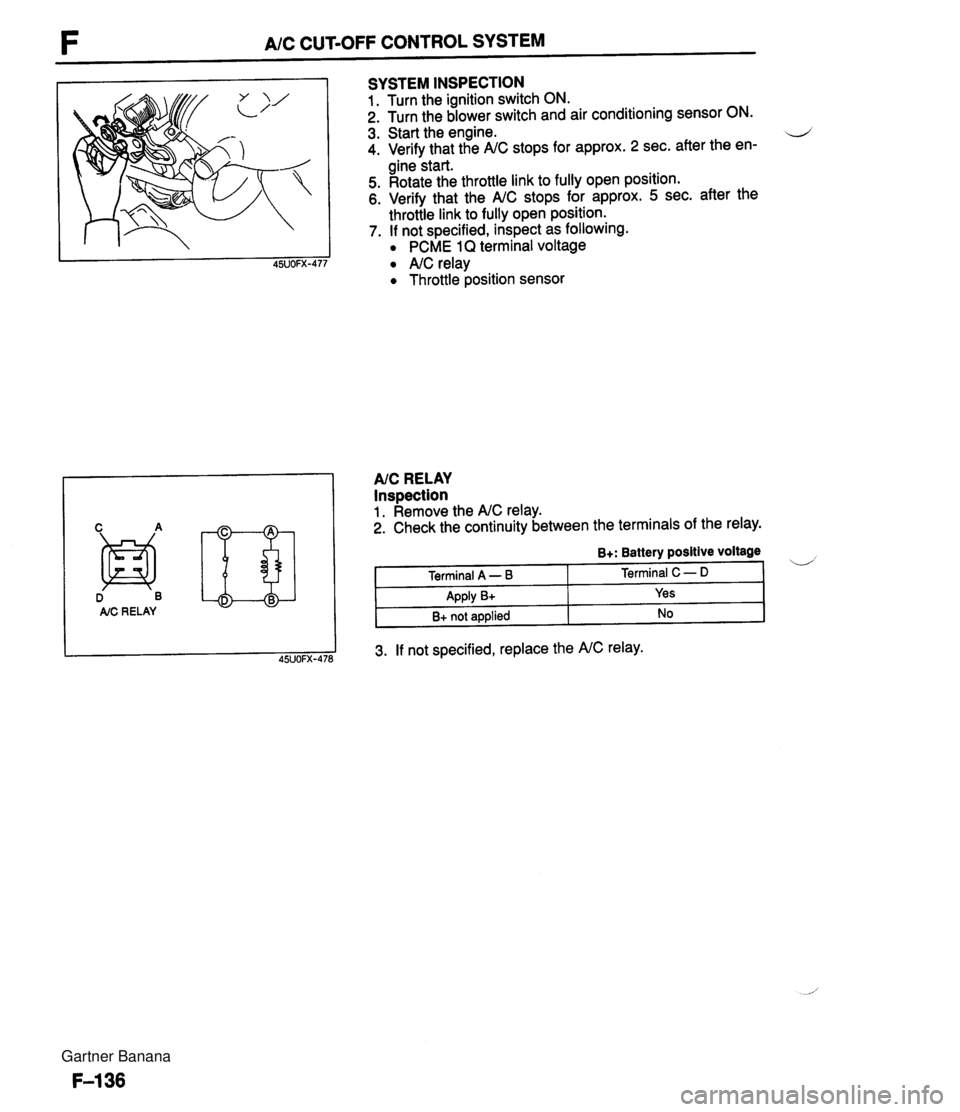
F A/C CUT-OFF CONTROL SYSTEM D B AIC RE LAY SYSTEM INSPECTION 1. Turn the ignition switch ON. 2. Turn the blower switch and air conditioning sensor ON. 3. Start the engine. d 4. Verify that the A/C stops for approx. 2 sec. after the en- gine start. 5. Rotate the throttle link to fully open position. 6. Verify that the A/C stops for approx. 5 sec. after the throttle link to fully open position. 7. If not specified, inspect as following. PCME 1Q terminal voltage A/C relay Throttle position sensor AIC RELAY Inspection 1. Remove the A/C relay. 2. Check the continuity between the terminals of the relay. 3. If not specified, replace the A/C relay. B+: Battery positive voltage Terminal A - B Apply B+ B+ not applied Terminal C - D Yes No Gartner Banana
Page 294 of 1708
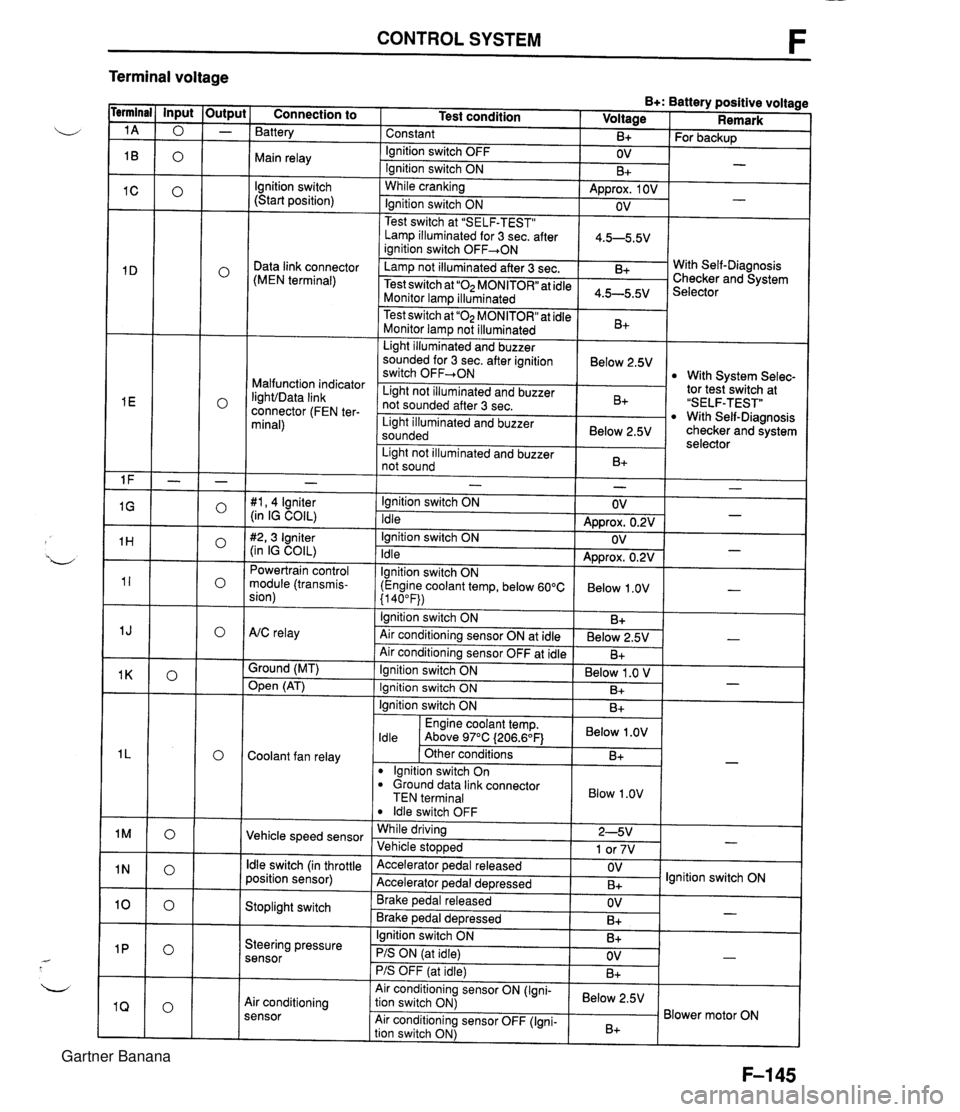
CONTROL SYSTEM F Terminal voltage B+: Battery positive voltage Test condition I Voltage I Remark - - - - - - - - - - - - - - - - - - Connection to Battery Constant Ignition switch OFF Main relay - B+ OV lgnition switch (Start position) For backup - Ignition switch ON While cranking Lamp illuminated for 3 sec. after 1 4.5-5.5V ianition switch OFF+ON 1 B+ Approx. 1 OV Ignition switch ON - - OV Data link connector (MEN terminal) Test switch at "SELF-TEST" .. Lamp not illuminated after 3 sec. Test switch at "02 MONITOR" at idle Monitor lam illuminated & 4.5-5.5v . . I Malfunction indicator IighVData link connector (FEN ter- minal) With Self-Diagnosis Checker and System Selector Test switch at "02 MONITOR" at idle Monitor lamp not illuminated Light illuminated and buzzer sounded for 3 sec. after ignition switch OFF-ON B+ tor tesiswitch at "SELF-TEST" With Self-Diagnosis checker and system selector Below 2.5V 1 Light illuminated and buzzer sounded 1 Below 2.5V I With System Selec- Light not illuminated and buzzer not sounded after 3 sec. I Light not illuminated and buzzer 1 n. 1 B+ not sound I D+ 1 - #I, 4 lgniter (in IG COIL) #2,3 Igniter (in IG COIL) Powertrain control module (transmis- sion) - Ignition switch ON Idle Ignition switch ON Idle lgnition switch ON (Engine coolant temp, below 60°C {I 40°F)) Ignition switch ON AtC relay Air conditioning sensor ON at idle Air conditioning sensor OFF at idle Ground (MT) - OV Approx. 0.2V OV Approx. 0.2V Below 1 .OV B+ Below 2.5V B+ - - - - , * Open (AT) - Ignition switch ON ( Below 1 .O V I Engine coolant temp. I Below .OV I ldle Above 97°C (206.6OF1 Ignition switch ON I I B+ Ignition switch ON Coolant fan relay B+ . - Other conditions lgnition switch On dround data link connector TEN terminal I Blow 1.0" I B+ Vehicle speed sensor ldle switch OFF While driving Vehicle sto~wed ldle switch (in throttle position sensor) 2-5V 1 or 7V . , Accelerator pedal released Accelerator ~edal de~ressed - Stoplight switch OV B+ Brake pedal released Brake ~edal deoressed lgnition switch ON Steering pressure sensor OV B+ I I - Ignition switch ON B+ - PIS ON (at idle) PIS OFF (at idle) Air conditioning sensor Air conditioning sensor ON (Igni- tion switch ON) Air conditioning sensor OFF (Igni- tion switch ON) OV B+ - Below 2.5V B+ Blower motor ON Gartner Banana