coolant MAZDA MX-5 1994 Workshop Manual
[x] Cancel search | Manufacturer: MAZDA, Model Year: 1994, Model line: MX-5, Model: MAZDA MX-5 1994Pages: 1708, PDF Size: 82.34 MB
Page 10 of 1708
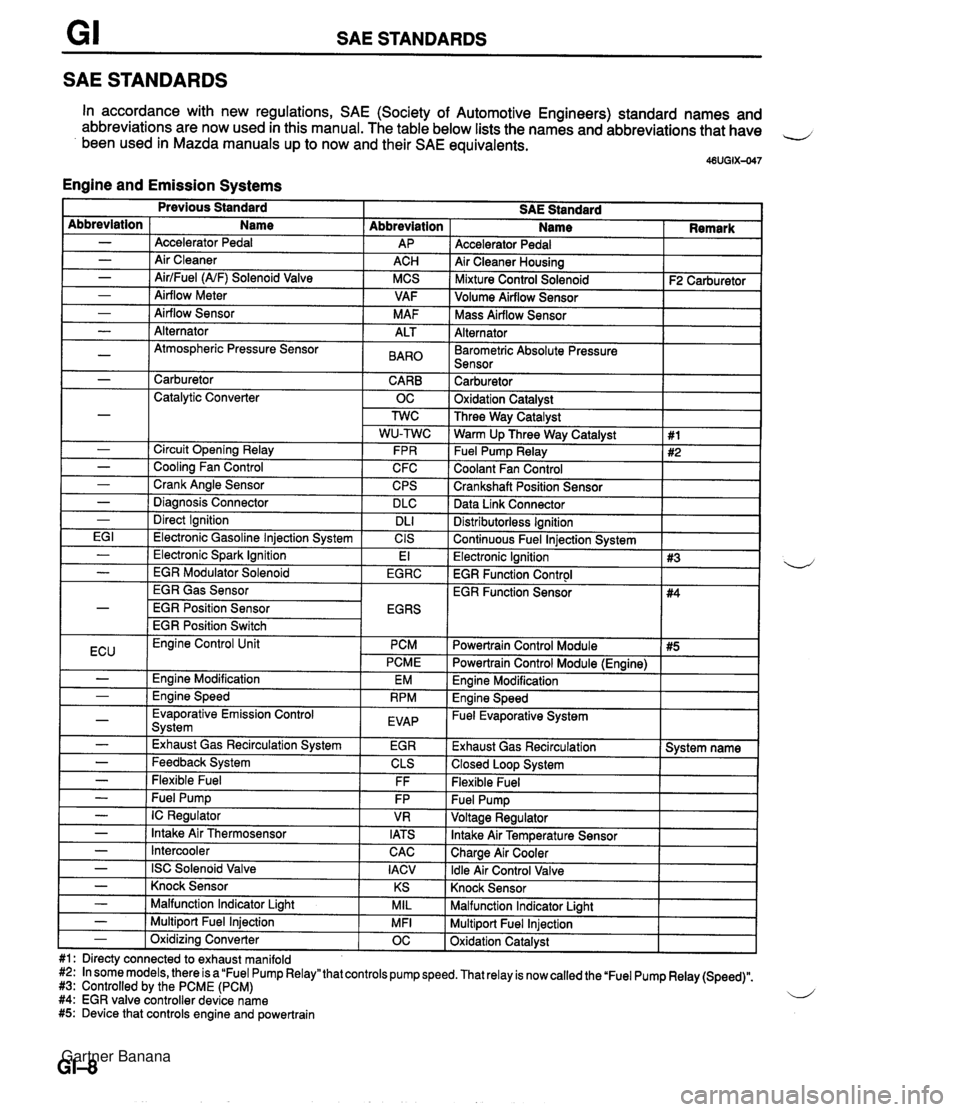
SAE STANDARDS SAE STANDARDS In accordance with new regulations, SAE (Society of Automotive Engineers) standard names and abbreviations are now used in this manual. The table below lists the names and abbreviations that have 4 been used in Mazda manuals up to now and their SAE equivalents. 46UGIX-047 Engine and Emission Systems Accelerator Pedal Air Cleaner Housing I Mixture Control Solenoid I F2 Carburetor ] Abbreviation AP ACH MCS VAF M AF Abbreviation - - - - - Volume Airflow Sensor I I Name Accelerator Pedal Air Cleaner AirlFuel (NF) Solenoid Valve Airflow Meter Airflow Sensor I Mass Airflow Sensor I I Alternator I I - - - -~ I Barometric Absolute Pressure I I Sensor I I Alternator Atmospheric Pressure Sensor I - 1 Carburetor CARB 1 Catalytic Converter OC ALT BAR0 Carburetor 1 Oxidation Catalvst I - - - - - I Direct Ignition I DL1 EG I 1 Electronic Gasoline lniection Svstem I CIS Three Way Catalyst Warm Up Three Way Catalyst Fuel Pump Relay Coolant Fan Control Crankshaft Position Sensor Data Link Connector Circuit Opening Relay Cooling Fan Control Crank Angle Sensor Diaanosis Connector Distributorless Ignition I Continuous Fuel lniection Svstem I 1 #1 #2 FPR C FC CPS DLC I Previous Standard SAE Standard Name I Remark - ( Electronic Spark Ignition EGR Gas Sensor EGR Position Sensor EGR Position Switch El Electronic Ignition 1 #3 EGR Function Control I - I EGR Modulator Solenoid I EGRC 4 ECU I Evaporative Emission Control Svstem I EVAP - - I -,--- I - I Exhaust Gas Recirculation System I EGR Engine Control Unit PCM PCME Engine Modification Ennine Speed EM RPM - - - - - Feedback System Flexible Fuel - I Intercooler Powertrain Control Module I #5 I EGR Function Sensor CLS FF Fuel Pump IC Regulator Intake Air Thermosensor CAC I Powertrain Control Module (Engine) I #4 FP VR IATS - I ISC Solenoid Valve I IACV Engine Modification I Engine Speed - Fuel Evaporative System I Exhaust Gas Recirculation 1 System name 1 Closed Loop System I Flexible Fuel Knock Sensor I I - ( Knock Sensor I KS I Malfunction Indicator Light I I - I Malfunction Indicator Liaht MIL Multiport Fuel Injection Oxidation Catalyst - 1 Multiport Fuel Injection #1: Directy connected to exhaust manifold #2: In some models, there is a "Fuel Pump Relay" that controls pump speed. That relay is now called the 'Fuel Pump Relay (Speed)". #3: Controlled by the PCME (PCM) 4 #4: EGR valve controller device name #5: Device that controls engine and powertrain MFI - 1 Oxidizina Converter OC Gartner Banana
Page 11 of 1708
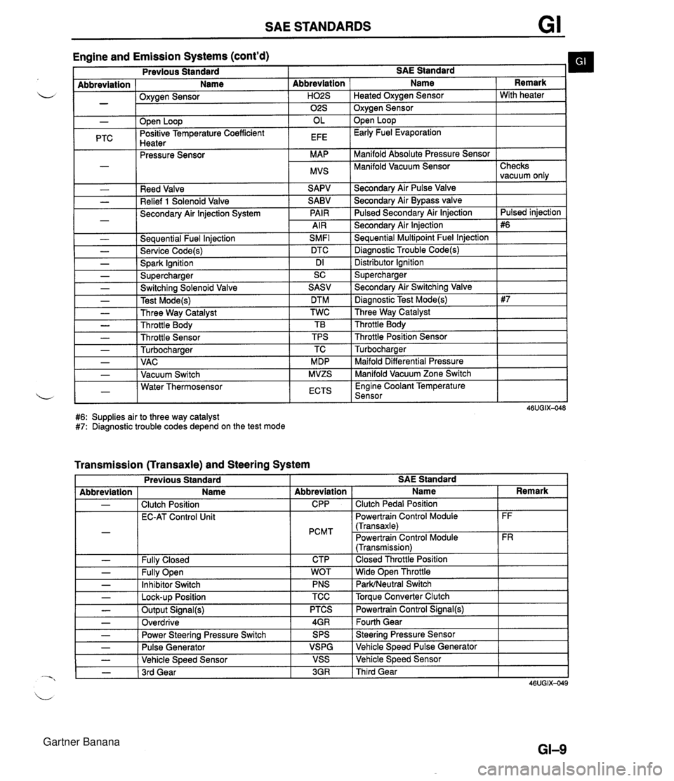
SAE STANDARDS Engine and Emission Systems (cont'd) I Previous Standard I SAE Standard b I - Abbreviation ( Name I Oxvaen Sensor - .w- - I I ." I 02s I Oxygen Sensor I - PTC Reed Valve Relief 1 Solenoid Valve Secondary Air lnjection System - Seauential Fuel lniection SMFl L - Service Code(s) DTC - Spark Ignition Dl - Supercharger SC Abbreviation I Name Open Loop Positive Temperature Coefficient Hnatar Secondarv Air Pulse Valve Remark . .--.-. Pressure Sensor Secondary Air Bypass valve Pulsed Secondarv Air lniection H02S I Heated Oxvaen Sensor I With heater OL EFE Secondary Air lnjection Sequential Multipoint Fuel lnjection Diagnostic Trouble Code(s) Open Loop Early Fuel Evaporation MAP MVS Distributor lgnition Supercharger Manifold Absolute Pressure Sensor Manifold Vacuum Sensor I - - - - - - Checks vacuum only Pulsed iniection - Switching Solenoid Valve Test Mode(s) Three Way Catalyst Throttle Body Throttle Sensor Turbocharaer .. Maifold Differential Pressure Manifold Vacuum Zone Switch , - I - 1 VAC I MDP 1-1 Water Thermosensor L - I Vacuum Switch I ECTS I Engine Coolant Temperature Sensor I SASV DTM TWC TB TPS TC MVZS #6: Supplies air to three way catalyst #7: Diagnostic trouble codes depend on the test mode - Secondary Air Switching Valve Diagnostic Test Mode(s) Three Way Catalyst Throttle Body Throttle Position Sensor Turbocharaer Transmission (Transaxle) and Steering System L - - Previous Standard I I I I Abbreviation - - - SAE Standard Fully Open Inhibitor Switch - I Lock-up Position - - Name Clutch Position EC-AT Control Unit Fullv Closed Abbreviation CPP PCMT CTP TCC I Torque Converter Clutch - - - WOT PNS Output Signal(s) Overdrive I Name Clutch Pedal Position Powertrain Control Module (Transaxle) Powertrain Control Module (Transmission) Closed Throttle Position Wide Open Throttle ParWNeutral Switch Power Steering Pressure Switch Pulse Generator Vehicle Speed Sensor - 1 3rd Gear Remark FF FR PTCS 4GR 3GR I Third Gear Powertrain Control Signal(@ Fourth Gear SPS VSPG VSS Steering Pressure Sensor Vehicle Speed Pulse Generator Vehicle Speed Sensor Gartner Banana
Page 12 of 1708

GI SAE STANDARDS Body Electrical System and Heater and Air Conditioner Systems Previous Standard SAE Standard - - Abbreviation I Name I Abbreviation 1 Name Remark 1 VB - - - AIC Switch Air Conditioner 46UGIX-050 #8: System name. Other related names are unchanged. Battery Voltage Coolant Level Sensor Ground Self-Diagnosis System ACS A/C B+ COLS GND OBD Air Conditioning Sensor Air Conditioner d Battery Positive Voltage Coolant Level Sensor Ground On-Board Diagnosis System #8 Gartner Banana
Page 23 of 1708
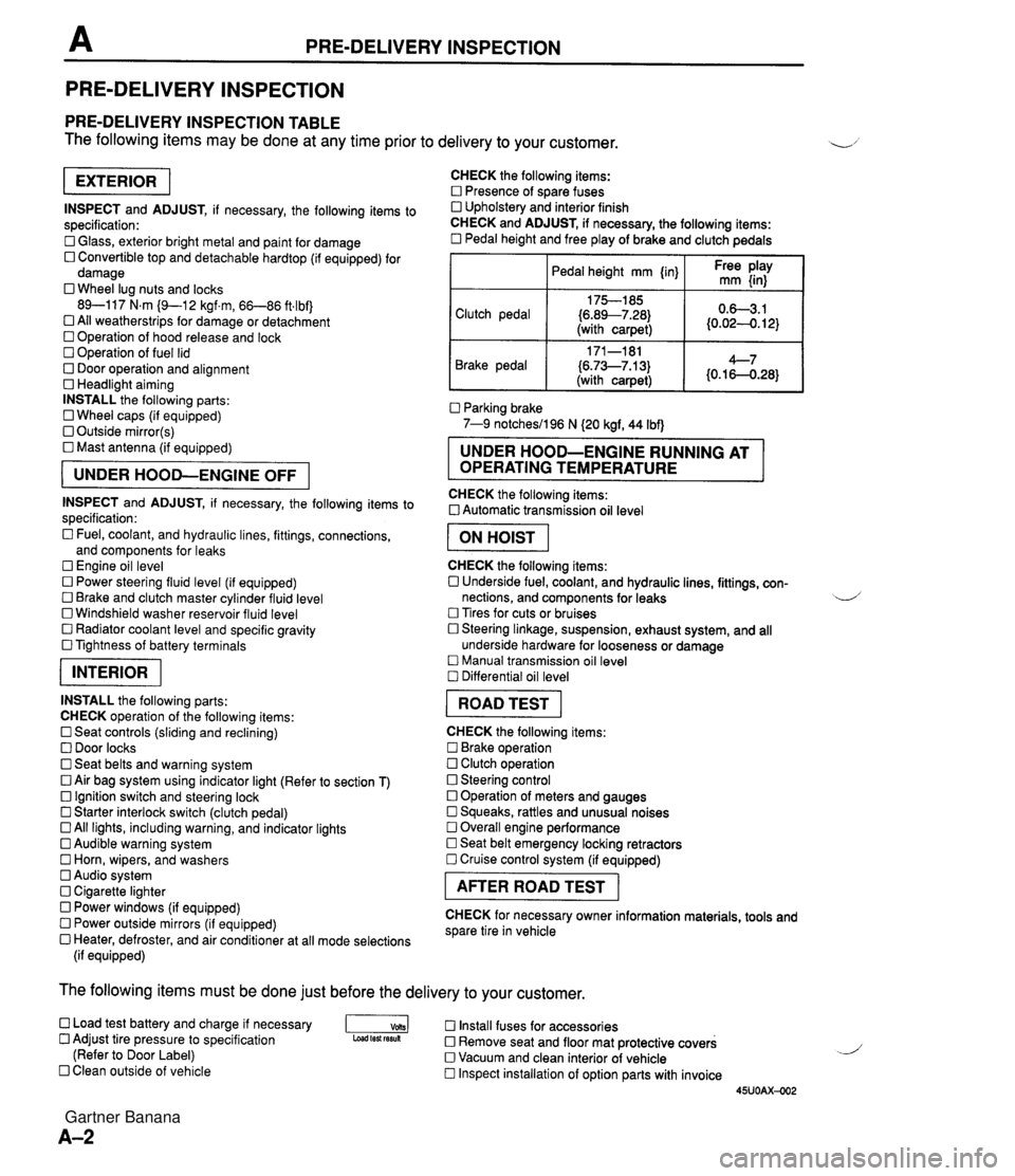
PRE-DELIVERY INSPECTION PRE-DELIVERY INSPECTION PRE-DELIVERY INSPECTION TABLE The following items may be done at any time prior to delivery to your customer. INSPECT and ADJUST, if necessary, the following items to specification: 0 Glass, exterior bright metal and paint for damage 0 Convertible top and detachable hardtop (if equipped) for damage 0 Wheel lug nuts and locks 89-117 N.m (9-1 2 kgf.m, 66-86 ft4bf) 0 All weatherstrips for damage or detachment Operation of hood release and lock Operation of fuel lid 0 Door operation and alignment Headlight aiming INSTALL the following parts: Wheel caps (if equipped) 0 Outside mirror(s) 0 Mast antenna (if equipped) UNDER HOOD-ENGINE OFF INSPECT and ADJUST, if necessary, the following items to specification : Fuel, coolant, and hydraulic lines, fittings, connections, and components for leaks Engine oil level 0 Power steering fluid level (if equipped) Brake and clutch master cylinder fluid level 0 Windshield washer reservoir fluid level 0 Radiator coolant level and specific gravity 0 Tightness of battery terminals pKiq INSTALL the following parts: CHECK operation of the following items: 0 Seat controls (sliding and reclining) 0 Door locks 0 Seat belts and warning system 0 Air bag system using indicator light (Refer to section T) Ignition switch and steering lock 0 Starter interlock switch (clutch pedal) All lights, including warning, and indicator lights 0 Audible warning system 0 Horn, wipers, and washers Audio system 0 Cigarette lighter Power windows (if equipped) 0 Power outside mirrors (if equipped) 0 Heater, defroster, and air conditioner at all mode selections (if equipped) CHECK the following items: Presence of spare fuses 0 Upholstery and interior finish CHECK and ADJUST, if necessary, the following items: 0 Pedal height and free play of brake and clutch pedals I Pedal height mm {in} I Ft: $iy I Clutch pedal {6.89--7.28) (with carpet) Parking brake 7-9 notchesil96 N (20 kgf, 44 Ibf) 0.63.1 (0.024. 12) Brake pedal RUNNING AT OPERATING TEMPERATURE CHECK the following items: 0 Automatic transmission oil level 171-181 (6.73--7.13) (with carpet) I ON HOIST I 4--7 {0.16-0.28} CHECK the following items: 0 Underside fuel, coolant, and hydraulic lines, fittings, con- nections, and components for leaks 4 Tires for cuts or bruises 0 Steering linkage, suspension, exhaust system, and all underside hardware for looseness or damage Manual transmission oil level Differential oil level I ROAD TEST I CHECK the following items: Brake operation Clutch operation 0 Steering control 0 Operation of meters and gauges Squeaks, rattles and unusual noises 0 Overall engine performance Seat belt emergency locking retractors 0 Cruise control system (if equipped) I AFTER ROAD TEST I CHECK for necessary owner information materials, tools and spare tire in vehicle The following items must be done just before the delivery to your customer. 0 Load test battery and charge if necessary -1 Install fuses for accessories Adjust tire pressure to specification Load test fesuk 0 Remove seat and floor mat protective covers (Refer to Door Label) 0 Vacuum and clean interior of vehicle Clean outside of vehicle Inspect installation of option parts with invoice 45UOAX-002 Gartner Banana
Page 32 of 1708
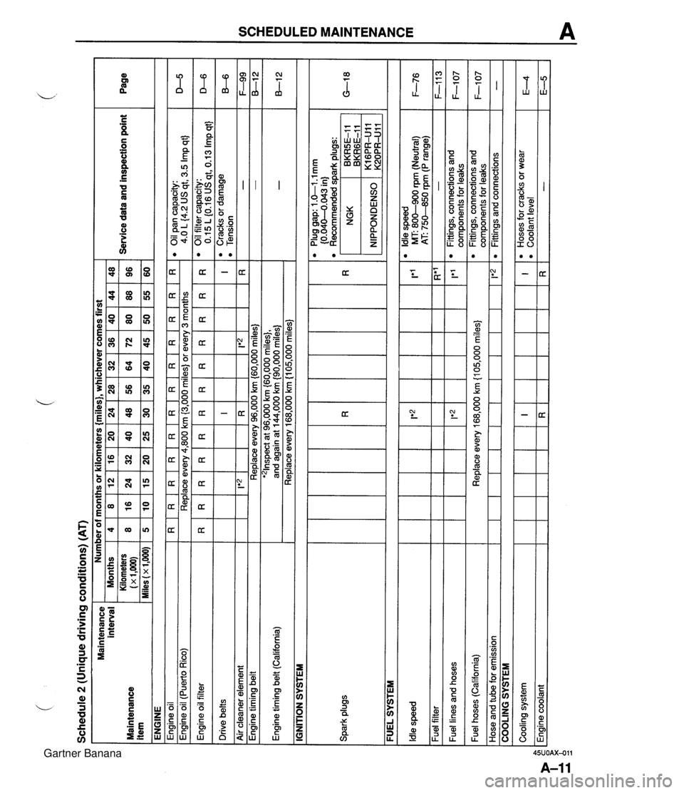
Schedule 2 (Unique driving conditions) (AT) Maintenance interval Maintenance item ENGINE Engine oil I R I R I R I R I R I R I R I R I R I R I R I R Engine oil filter Drive belts Number of months or kilometers {miles}, whichever comes first eoilpancapacity: 4.0 L {4.2 US qt, 3.5 Imp qt} Engine oil (Puerto Rico) I I IGNITION SYSTEM Service data and inspection point Months Kilometers (x 1,m) Miles (x 1,000) D-5 Replace every 4,800 km (3,000 miles) or every 3 months I I I I I I I I - - Engine timing belt (California) Spark plugs Page - - Air cleaner element I I FUEL SYSTEM 4 8 5 I F-99 8-1 2 -. . . '21nspect at 96,000 km {60,000 miles}, and again at 144,000 km {90,000 miles) Replace every 168,000 km (1 05,000 miles) - - R*' - 1'1 l Oilfiltercapacity: 0.15 L (0.16 US qt, 0.13 Imp qt} l Cracks or damage l Tension I R 1 Ie2 1 Engine timing belt ~ --- - - l Plug gap: 1 .&I -1 mm (0.040-4.043 in) l Recommended dark ~luas: 8 16 10 D-6 B-6 Replace every 96,000 km (60,000 miles) Idle speed Fuel filter Fuel lines and hoses NGK , BKRGE-11 BKR5E-I 1 12 24 15 IRI I*2 lt2 l Idle speed MT: 800-900 rpm (Neutral) 1 F-76 AT: 75M0 rpm (P range) 16 32 20 I!*'2 1 20 40 25 24 48 30 - Fittings, connections and com~onents for leaks 36 72 45 F-113 F-1 07 Fuel hoses (California) Hose and tube for emission 28 56 35 Cooling system Engine coolant 32 64 40 COOLING SYSTEM Replace every 168,000 km {I 05,000 miles} 1 1*2 48 96 60 40 80 50 I R 44 88 55 l Fittings, connections and components for leaks Fittings and connections F-1 07 - I R l Hoses for cracks or wear l Coolant level - E4 E-5 Gartner Banana
Page 35 of 1708
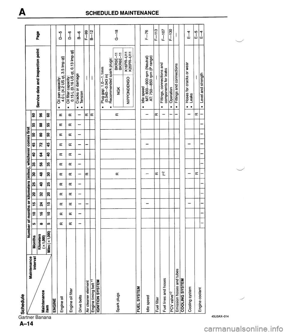
Schedule interval Maintenance ENGINE Number of months or kilometers {miles), whichever comes first I -. Months 5 10 15 20 25 30 35 40 45 50 55 60 Kilometers 8 16 24 32 40 48 56 64 72 80 88 96 - Service data and inspection point 1~1.000~ Page Spark plugs FUEL SYSTEM -- Plug gap: 1 .GI .l mm {0.04M.043 in) l Recommended spark plugs: D-5 D-6 B-6 F-99 8-1 2 IGNITION SYSTEM R I I Engine oil Engine oil filter Drive belts Air cleaner element Engine timing belt 'l R I R I F-76 F-1 1 3 F-107 F-I30 - Idle speed Fuel filter Fuel lines and hoses PCV valve'2 Emission hoses and tubes R I COOLING SYSTEM I Cooling system Engine coolant R I R I I E4 E-5 E4 I R I R I R I R I*z I l Hoses for cracks or wear l Leaks - Level and strength I R RR I R R R I I R I OilPancapacity: 4.0 L (4.2 US qt, 3.5 Imp qt) 0 Oil filter capacity: 0.15L(0.16USqt,0.13Impqt) 'Cracksordamage 0 Tension - - R I I I I I R I l ldle speed MT: 800-900 rpm (Neutral) AT 750-850 rpm (P range) - l Fittings, connections and components for leaks Operation Fittings and connections I I R I I I I I I I I I R I Gartner Banana
Page 38 of 1708

Before beginning any service procedure. refer to section T of this manual for air bag system service warnings and audio antitheft system alarm conditions . ENGINE INDEX ............................. B- 2 OUTLINE .......................... B- 3 SPECIFICATIONS ................ B- 3 TROUBLESHOOTING GUIDE ........ B- 3 ENGINE TUNE-UP .................. 8- 5 PREPARATION ................... B- 5 ENGINE OIL ..................... B- 5 ENGINE COOLANT ............... B- 5 DRIVE BELT ..................... 8- 6 HLA TROUBLESHOOTING GUIDE . 8- 8 IGNITION TIMING. IDLE SPEED .... B- 8 COMPRESSION .................... 8-10 INSPECTION ..................... B-10 ON-VEHICLE MAINTENANCE ....... B-11 PREPARATION ................... B-11 TIMING BELT ..................... 8-12 CYLINDER HEAD GASKET ........ B-16 H LA ............................. 8-20 FRONT OIL SEAL ................. 8-24 REAR OIL SEAL .................. 8-26 REMOVAL ......................... 8-28 PROCEDURE .................... B-28 ENGINE STAND MOUNTING ......... 8-32 PREPARATION ................... 8-32 PROCEDURE .................... B-33 DISASSEMBLY ..................... B-35 PREPARATION ................... 8-35 AUXILIARY PARTS ............... 8-36 TIMING BELT ..................... 8-37 CYLINDER HEAD ................. 8-39 CYLINDER BLOCK (EXTERNAL PARTS) ............. 8-42 CYLINDER BLOCK .............. (INTERNAL PARTS) 8-44 .............. INSPECTION I REPAIR 8-47 ................... PREPARATION 8-47 ................. CYLINDER HEAD 8-47 .............. VALVE MECHANISM 8-48 ...................... CAMSHAFT B-51 HLA ............................. 8-53 ............... CYLINDER BLOCK B-53 .......................... OIL JET B-54 PISTON. PISTON RING. AND ..................... PISTON PIN 8-55 CONNECTING ROD .............. B-56 ................... CRANKSHAFT 8-57 BEARING ........................ 8-57 TIMING BELT ..................... 8-58 TENSIONER. IDLER .............. 8-58 TENSIONER SPRING ............. 8-58 PULLEY ......................... 8-58 ........................ ASSEMBLY 8-59 ................... PREPARATION 8-59 CYLINDER BLOCK (INTERNAL PARTS) .............. B-60 CYLINDER BLOCK (EXTERNAL PARTS) ............. B-65 CYLINDER HEAD ................. B-69 TIMING BELT ..................... 8-73 ............... AUXILIARY PARTS 8-77 ..... ENGINE STAND DISMOUNTING 8-81 .................... PROCEDURE 8-81 INSTALLATION ..................... 8-83 .................... PROCEDURE 843 45UOBX-001 Gartner Banana
Page 39 of 1708

B INDEX INDEX 1. Timing belt Removal / Installation ....... page 8-1 2 2. Cylinder head gasket Replacement .............. page 6-1 6 3. HLA Removal / Installation ....... page 8-20 4. Front oil seal Replacement .............. page 6-24 5. Rear oil seal Replacement .............. page 6-26 INTAKE MANIFOLD COMPRESSION INSPECTION, PAGE B-10 TIGHTENING TORQUE STANDARD: 1,255 kPa (1 2.8 k f/cm2, 182 psi)-300 rpm 19-25 Nm (1.9-2.6 kgfq 14--18 ft4bf) MINIMUM: 883 kPa (9.0 kgflcm 9 , 128 psi}-300 rpm TIGHTENING TORQUE 3946 Nm i3.9--4.7 kgf m, 29-33 ftdbf) DRIVE BELT ADJUSTMENT. PAG ENGINE OIL INSPECTION, SERVICE, SECTION D DEFLECTION mm (in) ENGINE COOLANT INSPECTION, 6. Engine Removal .................. page 8-28 Engine stand mounting ..... page 6-32 Disassembly .............. page 6-35 Inspection / Repair ......... page B-47 Assembly ................. page 559 Engine stand dismounting ... page 8-81 , Installation ................ page B-83 SERVICE, SECTION E DRIVE BELT ALTERNATOR PIS. PIS + AlC AlC NEW 55-7.0 (0.224.27) 8.&9.0{0.324.35] 8.0-9.0{0.324.35) USED 6.0-7.5 (0.24-0.29) 9.0-10.0{0.364.39) 9.0-10.0{0.364.39} LIMIT 8.0 (0.31) 11.5 (0.45) 11.5 (0.453 Gartner Banana
Page 42 of 1708

ENGINE TUNE-UP ENGINE TUNE-UP PREPARATION SST I 49 9200 020 Tension gauge, V-ribbed belt For inspection of ignition timing and idle speed For inspection of drive belt tension ENGINE OIL 49 801 9 9AO System selector Warning Continuous exposure with USED engine oil has caused skin cancer in laboratory mice. Protect your skin by washing with soap and water im- mediately after this work. Inspection 1. Be sure the vehicle is on level ground. 2. Warm up the engine to normal operating temperature and stop it. 3. Wait for five minutes. 4. Remove the dipstick and check the oil level and condi- tion. 5. Add or replace oil if necessary. Note The distance between the L and F marks on the dip- stick represents 0.8 L (0.85 US qt, 0.70 Imp qt}. ENGINE COOLANT Inspection Coolant level (engine cold) Warning Removing the radiator cap or the coolant filler cap while the engine is running, or when the engine and radiator are hot is dangerous. Scalding cool- ant and steam can shoot out and cause serious in- jury. It can also damage the engine and cooling system. Turn off the engine and wait until it is cool. Even then, be very careful when removing the cap. Wrap a thick cloth around it and slowly turn it counterclockwise to the first stop. Step back while the pressure escapes. When you're sure all the pressure is gone, press down on the cap-still using a cloth - turn it, and remove it. 1. Verify that the coolant level is near the radiator filler neck. 2. Verify that the coolant level in the coolant reservoir is be- tween the FULL and LOW marks. 3. Add coolant if necessary. Gartner Banana
Page 43 of 1708

ENGINE TUNE-UP V-RIBBED BELT PIS or PIS + A/C EQUIPPED AIC EQUIPPED IDLER Coolant quality 1. Verify that there is no buildup of rust or scale around the radiator cap or radiator filler neck. 2. Verify that the coolant is free of oil. d 3. Replace the coolant if necessary. DRIVE BELT Inspection 1. Remove the air intake pipe. 2. Check the drive belts for wear, cracks, and fraying. Re- place if necessary. 3. Verify that the drive belts are correctly mounted on the pulleys. 4. Check the drive belt deflection when the engine is cold, or at least 30 minutes after the engine has stopped. Ap- ply moderate pressure 98 N (10 kgf, 22 Ibf) midway be- tween the specified pulleys. Deflection rnrn {in) Drive belt New' Used Limit Alternator 5.5-7.0 6.0-7.5 m.22-0.27) (0.24-0.29) 8.0 (0.31) t" NC 8.0-9.0 9'0-'0.0 11.5 {0.45} {0.32-0.35) {0.36-0.39) A belt that has been on a running engine for less than five minutes. 5. If the deflection is not within specification, adjust it. 6. Install the air intake pipe. Drive belt tension check Belt tension can be checked in place of belt deflection. Check the drive belt tension when the engine is cold, or at least 30 minutes after the engine has stopped. Using the SST, check the belt tension between any two pulleys. Gartner Banana