body dimensions MAZDA MX-5 1994 Workshop Manual
[x] Cancel search | Manufacturer: MAZDA, Model Year: 1994, Model line: MX-5, Model: MAZDA MX-5 1994Pages: 1708, PDF Size: 82.34 MB
Page 759 of 1708

Before beginning any service procedure. refer to section T of this manual for air bag system service warnings and audio antitheft system alarm conditions . BODY INDEX ............................. S- 2 HOOD ............................. S- 5 COMPONENTS ................... S- 5 DOOR ............................. S- 7 COMPONENTS ................... S- 7 WINDOW REGULATOR. GLASS. AND GUIDE ....................... S- 9 COMPONENTS ................... S- 9 ......... DOOR LOCK AND OPENER S-15 ................... COMPONENTS S-15 TRUNK LID ........................ S-16 COMPONENTS ................... S-16 .... TRUNK LID LOCK AND OPENER S-18 COMPONENTS ................... S-18 ......... POWER WINDOW SYSTEM S-19 .............. STRUCTURAL VIEW S-19 TROUBLESHOOTING ............. S-20 ........ b POWER WINDOW SWITCH S-22 ... POWER WINDOW REGULATOR S-22 ......... FUEL-FILLER LID OPENER S-23 COMPONENTS ................... S-23 FRONT BUMPER ................... S-24 COMPONENTS ................... S-24 REAR BUMPER .................... S-25 COMPONENTS ................... S-25 ........... MOLDING AND GARNISH S-27 COMPONENTS ................... S-27 OUTSIDE MIRROR ................. S-30 STRUCTURAL VIEW .............. S-30 ............. TROUBLESHOOTING S-31 POWER OUTSIDE MIRROR ....... S-33 POWER OUTSIDE MIRROR SWITCH ........................ S-33 COMPONENTS ................... S-34 WINDSHIELD WIPER AND WASHER . S-35 TROUBLESHOOTING ............. S-35 WIPER MOTOR .................. S-38 ................ WASHER MOTOR S-38 FRONT WIPER AND WASHER ........................ SWITCH S-38 ................... COMPONENTS S39 WINDSHIELD ...................... S-44 PREPARATION ................... S-44 ................... COMPONENTS S-44 REAR WINDOW GLASS ......... (DETACHABLE HARDTOP) S-48 PREPARATION ................... S48 ................... COMPONENTS S48 REAR WINDOW .............. (CONVERTIBLE TOP) S-52 ................... COMPONENTS S-52 ....... DASHBOARD AND CONSOLE S-56 ................... COMPONENTS S56 TRIM .............................. S-59 COMPONENTS ................... S-59 ................. FLOOR COVERING S-62 ................... COMPONENTS -21 SEAT BELT ........................ S-63 COMPONENTS ................... S-63 ...................... SEAT BELT S-64 ................ BUCKLE SWITCH S-64 SEAT .............................. S-65 ................... COMPONENTS S-65 ................ CONVERTIBLE TOP S-67 PREPARATION ................... S-67 ................... COMPONENTS S-67 ........... DETACHABLE HARDTOP S-81 COMPONENTS ................... S-81 BRACE BAR ....................... S-84 ................... COMPONENTS S-84 ......... UNDERBODY DIMENSIONS S-85 PROJECTED DIMENSIONS ........ S-85 ..... STRAIGHT-LINE DIMENSIONS S-87 45uoSx-001 Gartner Banana
Page 844 of 1708

s UNDERBODY DIMENSIONS BUMPER BRACKET MOUNTING NUT FRAME REFERENCE HOLE $1 6 (0.63) STABILIZER MOUNTING NUT FRONT FENDER PANEL MOUNTING NUT SUSPENSION MOUNTING BOLT FRONT MOUNTING BLOCK FRAME REFERENCE HOLE 12 x 18 (0.47 x 0.71) CROSSMEMBER MOUNTING NUT FRONT FENDER PANEL MOUNTING NUT CROSSMEMBER MOUNTING NUT FRAME REFERENCE HOLE @I2 (0.47) FRAME REFERENCE HOLE $20 (0.79) FRAME REFERENCE HOLE 12 x 18 (0.47 x 0.71) FRAME REFERENCE HOLE $12 (0.47) SUSPENSION MOUNTING BOLT SUSPENSION MOUNTING NUT REAR MOUNTING BLOCK SUSPENSION MOUNTING BOLT FRAME REFERENCE HOLE 16 x 22 (0.63 x 0.871 BUMPER BRACKET REFERENCE HOLE $7 (0.281 BUMPER MOUNTING HOLE 12 x 14 (0.47 x 0.55) mm {in) Gartner Banana
Page 845 of 1708
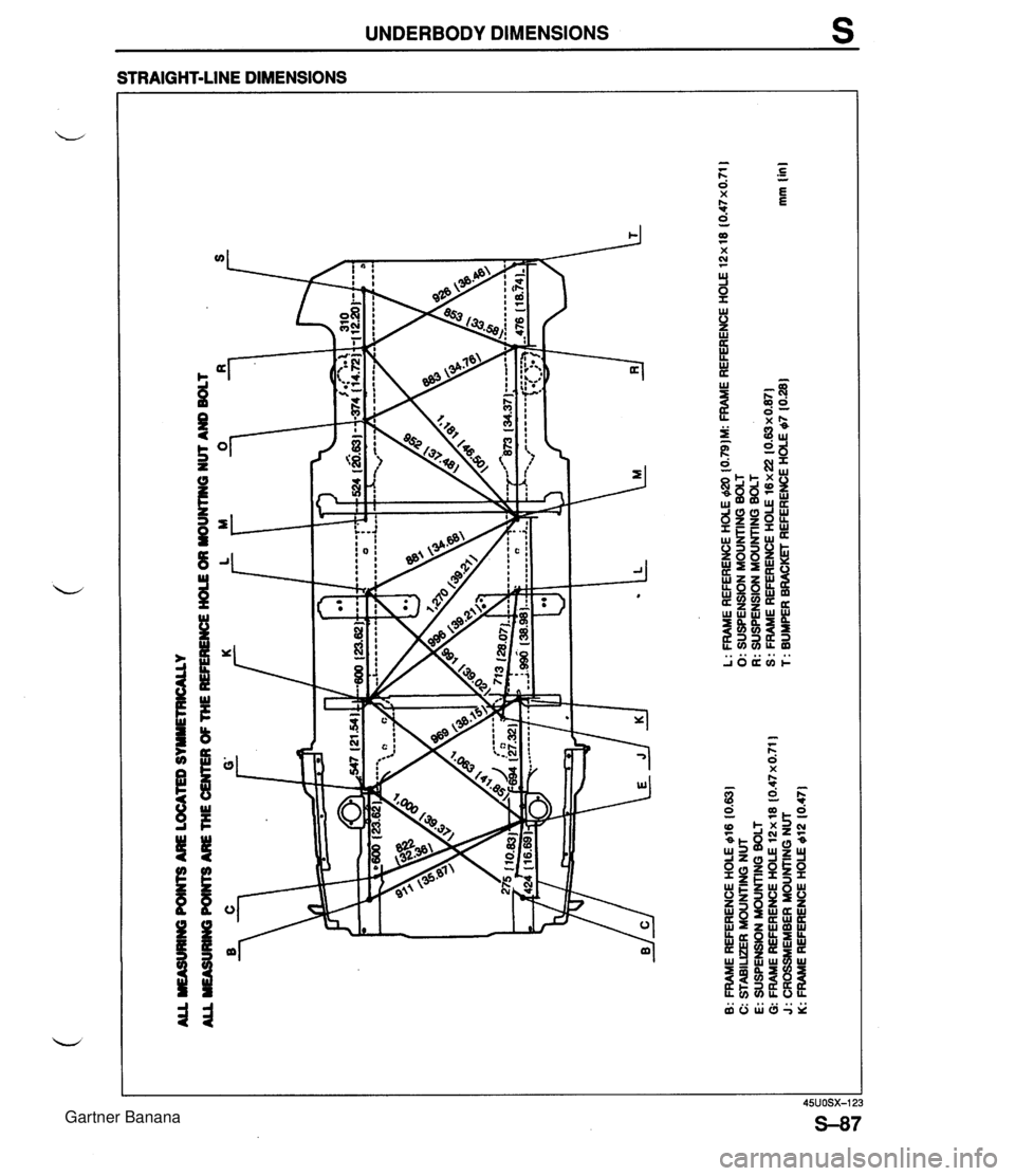
UNDERBODY DIMENSIONS s STRAIGHT-LINE DIMENSIONS Gartner Banana
Page 1254 of 1708
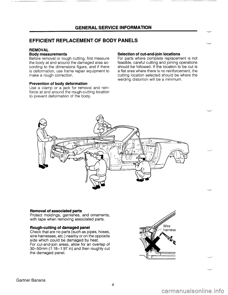
GENERAL SERVICE INFORMATION w EFFICIENT REPLACEMENT OF BODY PANELS V REMOVAL Body measurements Selection of cut-and-join locations Before removal or rough cutting, first measure For parts where complete replacement is not the body at and around the damaged area ac- feasible, careful cutting and joining operations cording to the dimensions figure, and if there should be followed. If the location to be cut is is deformation, use frame repair equipment to a flat area where there is no reinforcement, the make a rough correction. cutting location selected should be where the welding distortion will be a minimum. Prevention of body deformation Use a clamp or a jack for removal and rein- force at and around the rough-cutting location to prevent deformation of the body. Removal of associated parts Protect moldings, garnishes, and ornaments, with tape when removing associated parts. Rough-cutting of damaged panel Check that are no parts (such as pipes, hoses, wire harnesses, etc.) nearby or on the opposite side which could be damaged by heat. For cut-and-join areas, allow for an overlap of 30-50mm (1.18-1.97 in) and then roughly cut the damaged panel. Gartner Banana
Page 1256 of 1708

GENERAL SERVICE INFORMATION d INSTALLATION Checking pre-weld measurements and matching Align to the standard reference dimensions, based upon the body dimensions illustration, so that new parts are installed at the correct position. Welding notes Welding should be performed in accordance with the following reference standards. Note a) Plug welding should be performed by the CO2 gas shielded-arc welding method. b) Panel connections by brazing should be only at the indicated locations. Original welding Repair welding Pitch: 50mm Pitch: within 35mm (1.97 in) Original number of Spot welding welds x 1.3 or more Original spot welding Repair welding If 3rnm (0.12 in) or more Original number of welds or more Plug welding Spot welding notes OXXX Original spot weld @Before spot welding, make a trial weld; If satisfactory, proceed with the actual weld- ing. the tip contact surface and facing surfaces ~~[l/jLJL!= @Before spot welding, check once again that - Em -- to be welded are completely clean. @Because the weld strength is affected by the / shape of the spot welder tip, the tip should always be properly maintained, and, in ad- Hammer and chisel Test piece method method dition, in order to minimize problems caused by overheating, a certain amount of cooling time should be allowed after each 5 or 6 weld points. @Spot welds should, as a general rule, be & U made at points other than the originally Center diameter: lr welded points. w 3mm (0.12 in) n 2 Yi'%%Lr: 415 of tip Gartner Banana
Page 1261 of 1708
DIMENSIONS BODY DIMENSIONS ................................................. 12 EXPLANATION OF BODY DIMENSIONS ................... 12 PROJECTED DIMENSIONS ......................................... 13 UNDERBODY PROJECTED DIMENSIONS ............. 13 STRAIGHT-LINE DIMENSIONS .................................... 14 UNDERBODY STRAIGHT-LINE DIMENSIONS ....... 14 FRONT BODY STRAIGHT-LINE DIMENSIONS ...... 16 CABIN SIDE FRAME STRAIGHT-LINE DIMENSIONS .......................................................... 18 INTERIOR STRAIGHT-LINE DIMENSIONS (FRONT) ............................................................... 19 INTERIOR STRAIGHT-LINE DIMENSIONS (REAR) ................................................................... 20 REAR BODY STRAIGHT-LINE DIMENSIONS ......... 21 Gartner Banana
Page 1262 of 1708

BODY DIMENSIONS V The front suspension is a MacPherson strut style. Adjustment of the front wheel alignment is limited to camber adjustment. The front wheel alignment is determined by accuracy of the body itself. Accurate measurement and dimensional accuracy based upon the body dimensions are required when repairs are made. EXPLANATION OF BODY DIMENSIONS PROJECTED DIMENSIONS Flat-plane dimensions are those dimensions as measured on a flat surface projected from certain designated standard points of the body. STRAIGHT-LINE DIMENSIONS (ACTUAL DIMENSIONS) w Actual dimensions are those dimensions actually measured in a straight line between two points. Note Before the work, adjust the body according to the standard measurements and check the fit with associating parts, then proceed with the work. Front fender installation nuts 7 I Projected dimensions (Flat-plane dimensions) Gartner Banana
Page 1263 of 1708
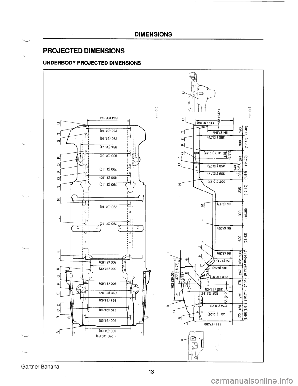
DIMENSIONS L PROJECTED DIMENSIONS L UNDERBODY PROJECTED DIMENSIONS Gartner Banana
Page 1266 of 1708
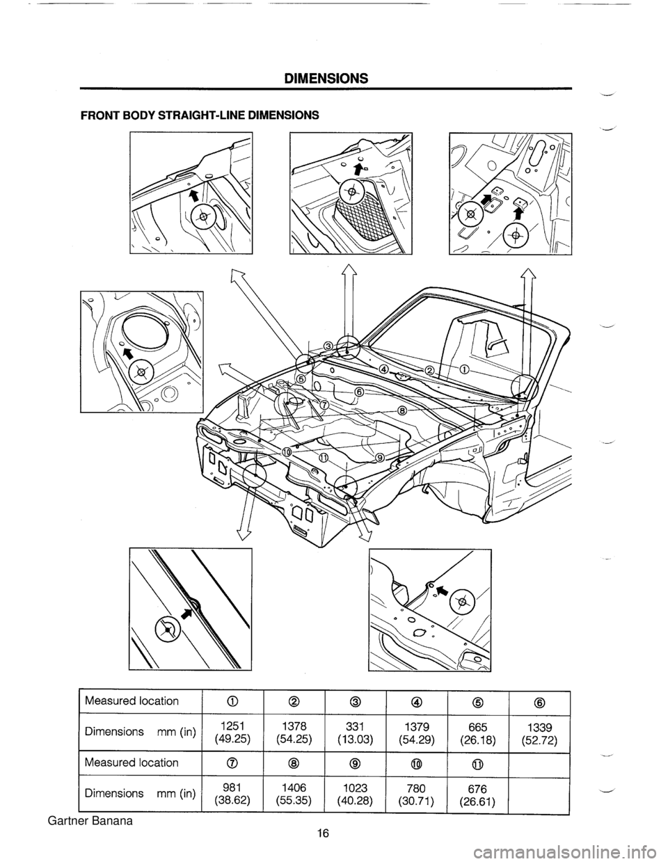
DIMENSIONS FRONT BODY STRAIGHT-LINE DIMENSIONS Measured location Dimensions mm (in) Measured location Dimensions mm (in) 0 1251 (49.25) 0 98 1 (38,62) 0 1378 (54.25) @ 1406 (55.35) 0 331 (13.03) @ 1023 (40.28) @ 1379 (54.29) @ 780 (30.71) 0 665 (26.18) 0 676 (26.61) @ 1339 (52.72) Gartner Banana
Page 1267 of 1708
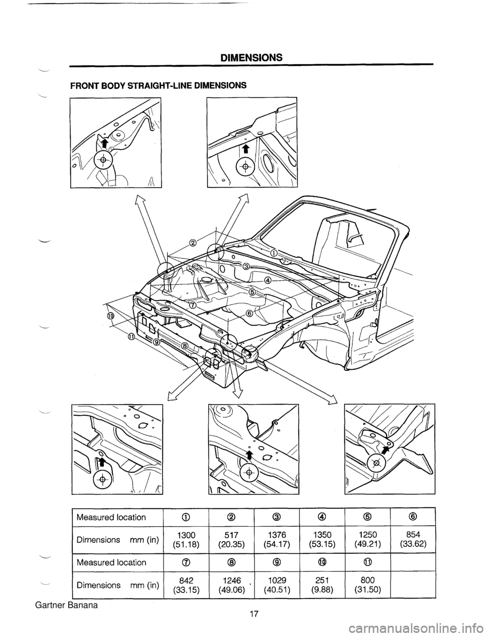
DIMENSIONS L FRONT BODY STRAIGHT-LINE DIMENSIONS @ 854 (33.62) 0 1250 (49.21) 0 800 (31.50) @ 1350 (53.15) @ 25 1 (9.88) 0 1376 (54.17) 0 1029 (40.51) 0 517 (20.35) @ 1246 , (49.06) Measured location Dimensions mm (in) Measured location Dimensions mm (in) 0 1300 (51 8) 0 842 (33.1 5) Gartner Banana