light MAZDA MX-5 1994 Workshop Manual
[x] Cancel search | Manufacturer: MAZDA, Model Year: 1994, Model line: MX-5, Model: MAZDA MX-5 1994Pages: 1708, PDF Size: 82.34 MB
Page 3 of 1708
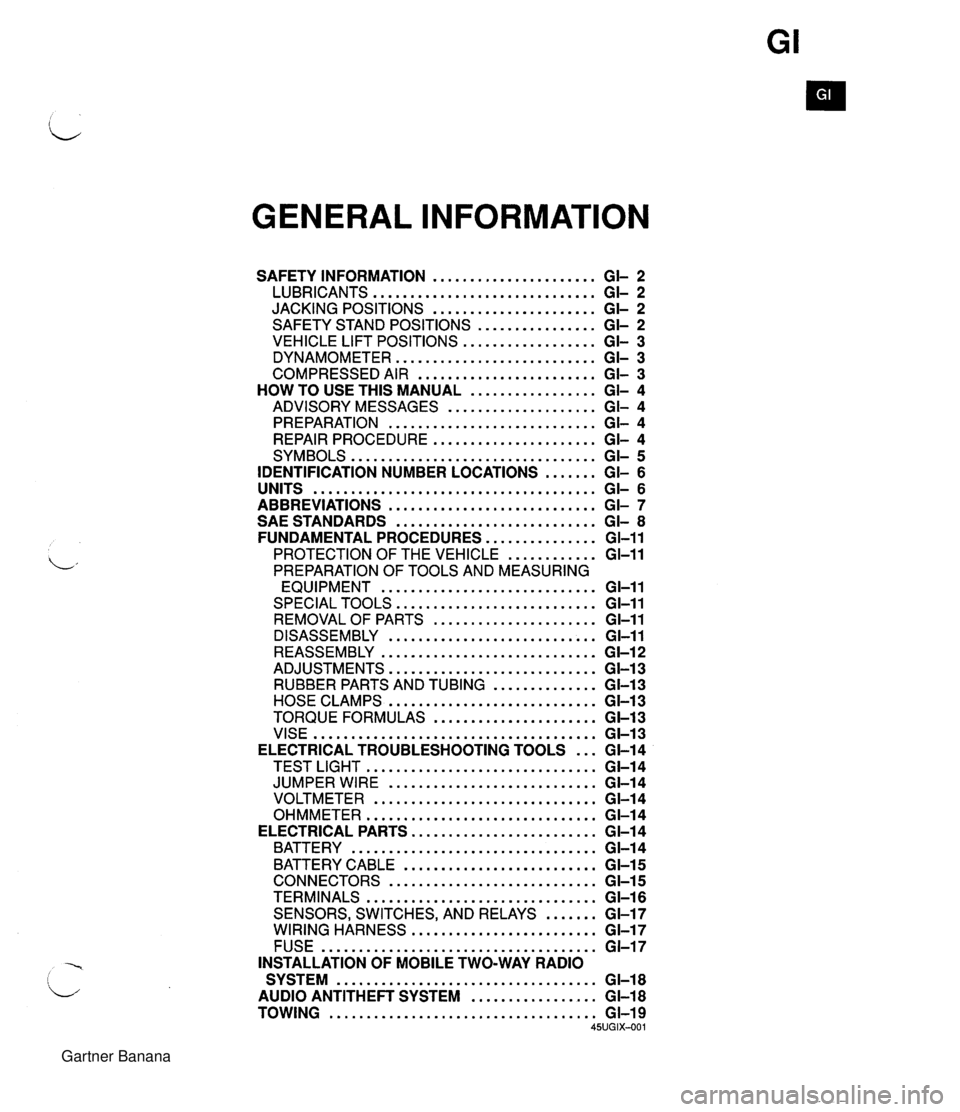
GENERAL INFORMATION SAFETY INFORMATION ...................... GI- 2 LUBRICANTS .............................. GI- 2 JACKING POSITIONS ...................... GI- 2 SAFETY STAND POSITIONS ................ GI- 2 VEHICLE LIFT POSITIONS .................. GI- 3 DYNAMOMETER ........................... GI- 3 COMPRESSED AIR ........................ GI- 3 HOW TO USE THIS MANUAL ................. GI- 4 ADVISORY MESSAGES .................... GI- 4 PREPARATION ............................ GI- 4 REPAIR PROCEDURE ...................... GI- 4 SYMBOLS ................................. GI- 5 IDENTIFICATION NUMBER LOCATIONS ....... GI- 6 UNITS ...................................... GI- 6 ABBREVIATIONS ............................ GI- 7 SAE STANDARDS ........................... GI- 8 FUNDAMENTAL PROCEDURES ............... GI-11 PROTECTION OF THE VEHICLE ............ GI-11 PREPARATION OF TOOLS AND MEASURING EQUIPMENT ............................. GI-11 SPECIAL TOOLS ........................... GI-11 REMOVALOF PARTS ...................... GI-11 DISASSEMBLY ............................ GI-11 REASSEMBLY ............................. GI-1 2 ADJUSTMENTS ............................ GI-13 RUBBER PARTS AND TUBING .............. GI-13 HOSE CLAMPS ............................ GC13 TORQUE FORMULAS ...................... GI-13 VISE ...................................... GI-13 ELECTRICAL TROUBLESHOOTING TOOLS ... GI-14 TEST LIGHT ............................... GI-14 JUMPER WIRE ............................ GC14 VOLTMETER .............................. GI-14 OHMMETER ............................... GI-14 ELECTRICAL PARTS ......................... GI-1 4 BATTERY ................................. GI-1 4 BATTERY CABLE .......................... GI-1 5 CONNECTORS ............................ GI-15 TERMINALS ............................... GI-16 SENSORS. SWITCHES. AND RELAYS ....... GI-17 WIRING HARNESS ......................... GI-17 FUSE ..................................... GI-17 INSTALLATION OF MOBILE TWO-WAY RADIO SYSTEM ................................... GI-18 AUDIO ANTITHEFT SYSTEM ................. GI-18 TOWING .................................... GI-19 45UGIX-001 Gartner Banana
Page 9 of 1708
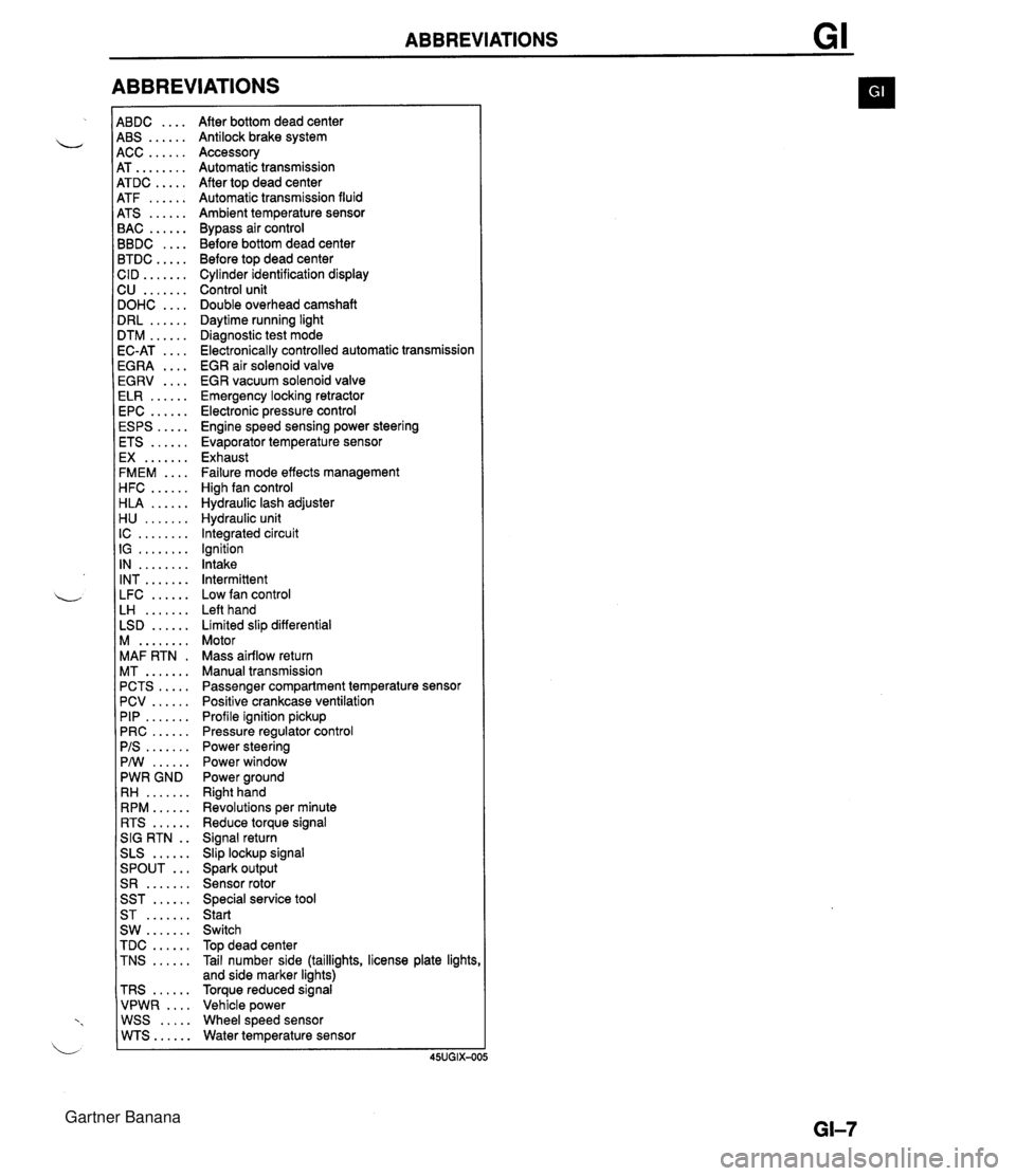
ABBREVIATIONS 4BDC .... 4BS ...... 4CC ...... 4T ........ 4TDC ..... 4TF ...... 4TS ...... 3AC ...... 3BDC .... 3TDC ..... :ID ....... 2U ....... IOHC .... IRL ...... ITM ...... IC-AT .... iGRA .... EGRV .... ELR ...... EPC ...... ESPS ..... ETS ...... EX ....... FMEM .... HFC ...... HLA ...... H U ....... IC ........ IG ........ IN ........ INT ....... LFC ...... LH ....... LSD ...... M ........ MAF RTN . MT ....... PCTS ..... PCV ...... PIP ....... PRC ...... PIS ....... PMI ...... PWR GND RH ....... RPM ...... RTS ...... SIG RTN . . SLS ...... ... SPOUT S R ....... SST ...... ST ....... SW ....... TDC ...... TNS ...... TRS ...... VPWR .... WSS ..... WTS...... After bottom dead center Antilock brake system Accessory Automatic transmission After top dead center Automatic transmission fluid Ambient temperature sensor Bypass air control Before bottom dead center Before top dead center Cylinder identification display Control unit Double overhead camshaft Daytime running light Diagnostic test mode Electronically controlled automatic transmission EGR air solenoid valve EGR vacuum solenoid valve Emergency locking retractor Electronic pressure control Engine speed sensing power steering Evaporator temperature sensor Exhaust Failure mode effects management High fan control Hydraulic lash adjuster Hydraulic unit Integrated circuit Ignition Intake Intermittent Low fan control Left hand Limited slip differential Motor Mass airflow return Manual transmission Passenger compartment temperature sensor Positive crankcase ventilation Profile ignition pickup Pressure regulator control Power steering Power window Power ground Right hand Revolutions per minute Reduce torque signal Signal return Slip lockup signal Spark output Sensor rotor Special service tool Start Switch Top dead center Tail number side (taillights, license plate lights and side marker lights) Torque reduced signal Vehicle power Wheel speed sensor Water temperature sensor Gartner Banana
Page 10 of 1708
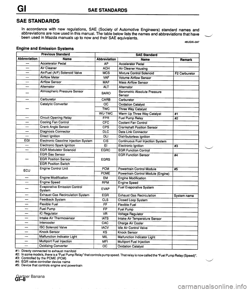
SAE STANDARDS SAE STANDARDS In accordance with new regulations, SAE (Society of Automotive Engineers) standard names and abbreviations are now used in this manual. The table below lists the names and abbreviations that have 4 been used in Mazda manuals up to now and their SAE equivalents. 46UGIX-047 Engine and Emission Systems Accelerator Pedal Air Cleaner Housing I Mixture Control Solenoid I F2 Carburetor ] Abbreviation AP ACH MCS VAF M AF Abbreviation - - - - - Volume Airflow Sensor I I Name Accelerator Pedal Air Cleaner AirlFuel (NF) Solenoid Valve Airflow Meter Airflow Sensor I Mass Airflow Sensor I I Alternator I I - - - -~ I Barometric Absolute Pressure I I Sensor I I Alternator Atmospheric Pressure Sensor I - 1 Carburetor CARB 1 Catalytic Converter OC ALT BAR0 Carburetor 1 Oxidation Catalvst I - - - - - I Direct Ignition I DL1 EG I 1 Electronic Gasoline lniection Svstem I CIS Three Way Catalyst Warm Up Three Way Catalyst Fuel Pump Relay Coolant Fan Control Crankshaft Position Sensor Data Link Connector Circuit Opening Relay Cooling Fan Control Crank Angle Sensor Diaanosis Connector Distributorless Ignition I Continuous Fuel lniection Svstem I 1 #1 #2 FPR C FC CPS DLC I Previous Standard SAE Standard Name I Remark - ( Electronic Spark Ignition EGR Gas Sensor EGR Position Sensor EGR Position Switch El Electronic Ignition 1 #3 EGR Function Control I - I EGR Modulator Solenoid I EGRC 4 ECU I Evaporative Emission Control Svstem I EVAP - - I -,--- I - I Exhaust Gas Recirculation System I EGR Engine Control Unit PCM PCME Engine Modification Ennine Speed EM RPM - - - - - Feedback System Flexible Fuel - I Intercooler Powertrain Control Module I #5 I EGR Function Sensor CLS FF Fuel Pump IC Regulator Intake Air Thermosensor CAC I Powertrain Control Module (Engine) I #4 FP VR IATS - I ISC Solenoid Valve I IACV Engine Modification I Engine Speed - Fuel Evaporative System I Exhaust Gas Recirculation 1 System name 1 Closed Loop System I Flexible Fuel Knock Sensor I I - ( Knock Sensor I KS I Malfunction Indicator Light I I - I Malfunction Indicator Liaht MIL Multiport Fuel Injection Oxidation Catalyst - 1 Multiport Fuel Injection #1: Directy connected to exhaust manifold #2: In some models, there is a "Fuel Pump Relay" that controls pump speed. That relay is now called the 'Fuel Pump Relay (Speed)". #3: Controlled by the PCME (PCM) 4 #4: EGR valve controller device name #5: Device that controls engine and powertrain MFI - 1 Oxidizina Converter OC Gartner Banana
Page 15 of 1708
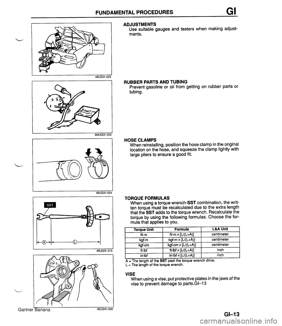
FUNDAMENTAL PROCEDURES GI ADJUSTMENTS Use suitable gauges and testers when making adjust- ments. RUBBER PARTS AND TUBING Prevent gasoline or oil from getting on rubber parts or tubing. HOSE CLAMPS When reinstalling, position the hose clamp in the original location on the hose, and squeeze the clamp lightly with large pliers to ensure a good fit. VISE When using a vise, put protective plates in the jaws of the vise to prevent damage to parkGI-1 3 TORQUE FORMULAS When using a torque wrench-SST combination, the writ- ten torque must be recalculated due to the extra length that the SST adds to the torque wrench. Recalculate the torque by using the following formulas. Choose the for- mula that applies to you. GI-I 3 L&A Unit centimeter centimeter centimeter inch inch Torque Unit N.m kgfm kgfcm ft.lbf in-lbf A = The length of the SST past the torque wrench drive. L = The length of the torque wrench. Formula N,m x [U(L+A)] kgf.m x [U(L+A)] kgfcrn x [U(L+A)] ft4bf x [U(L+A)] in.lbf x [U(L+A)] Gartner Banana
Page 16 of 1708
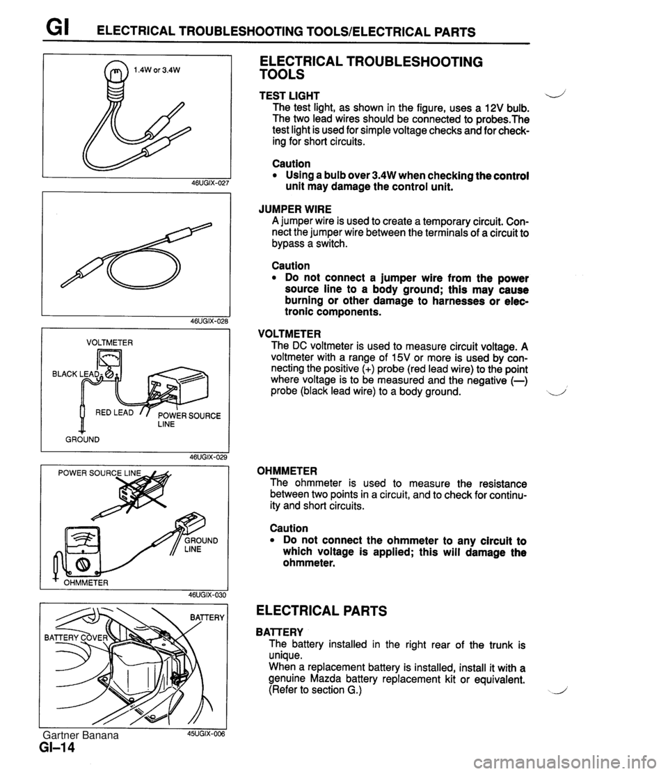
G I ELECTRICAL TROUBLESHOOTING TOOLSIELECTRICAL PARTS I VOLTMETER I BLACK LINE GROUND ELECTRICAL TROUBLESHOOTING TOOLS TEST LIGHT 4) The test light, as shown in the figure, uses a 12V bulb. The two lead wires should be connected to probes.The test light is used for simple voltage checks and for check- ing for short circuits. Caution Using a bulb over 3.4W when checking the control unit may damage the control unit. JUMPER WIRE A jumper wire is used to create a temporary circuit. Con- nect the jumper wire between the terminals of a circuit to bypass a switch. Caution Do not connect a jumper wire from the power source line to a body ground; this may cause burning or other damage to harnesses or elec- tronic components. VOLTMETER The DC voltmeter is used to measure circuit voltage. A voltmeter with a range of 15V or more is used by con- necting the positive (+) probe (red lead wire) to the point where voltage is to be measured and the negative (-) probe (black lead wire) to a body ground. d OHMMETER The ohmmeter is used to measure the resistance between two points in a circuit, and to check for continu- ity and short circuits. I I 45UGIX-006 GI-I 4 Caution Do not connect the ohmmeter to any circuit to which voltage is applied; this will damage the ohmmeter. ELECTRICAL PARTS BAlTERY The battery installed in the right rear of the trunk is unique. When a replacement battery is installed, install it with a genuine Mazda battery replacement kit or equivalent. (Refer to section G.) J Gartner Banana
Page 18 of 1708
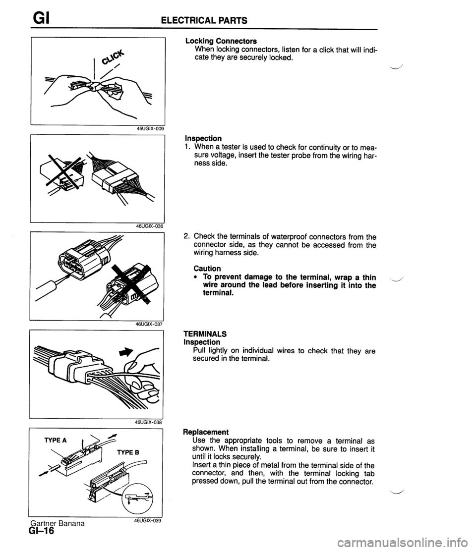
GI ELECTRICAL PARTS Locking Connectors When locking connectors, listen for a click that will indi- cate they are securely locked. 4' Inspection 1. When a tester is used to check for continuity or to mea- sure voltage, insert the tester probe from the wiring har- ness side. I I 46UGIX-039 GI-I 6 2. Check the terminals of waterproof connectors from the connector side, as they cannot be accessed from the wiring harness side. Caution To prevent damage to the terminal, wrap a thin ..J wire around the lead before inserting it into the terminal. TERMINALS lnspection Pull lightly on individual wires to check that they are secured in the terminal. Replacement Use the appropriate tools to remove a terminal as shown. When installing a terminal, be sure to insert it until it locks securely. Insert a thin piece of metal from the terminal side of the connector, and then, with the terminal locking tab pressed down, pull the terminal out from the connector. b' Gartner Banana
Page 19 of 1708
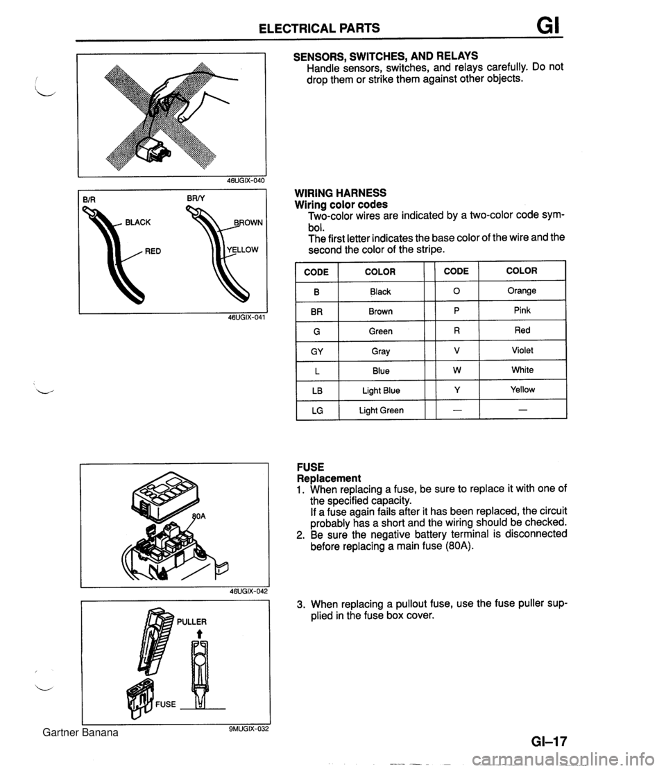
ELECTRICAL PARTS GI SENSORS, SWITCHES, AND RELAYS Handle sensors, switches, and relays carefully. Do not drop them or strike them against other objects. kD YELLOW WIRING HARNESS Wiring color codes Two-color wires are indicated by a two-color code sym- bol. The first letter indicates the base color of the wire and the second the color of the stripe. IGI Green 11 R 1 Red I B BR COLOR FUSE Replacement 1. When replacing a fuse, be sure to replace it with one of the specified capacity. If a fuse again fails after it has been replaced, the circuit probably has a short and the wiring should be checked. 2. Be sure the negative battery terminal is disconnected before replacing a main fuse (80A). CODE CODE Black Brown GY L LB LG 3. When replacing a pullout fuse, use the fuse puller sup- plied in the fuse box cover. COLOR 0 P Gray Blue Light Blue Light Green Orange Pink V W Y - Violet White Yellow - Gartner Banana
Page 23 of 1708
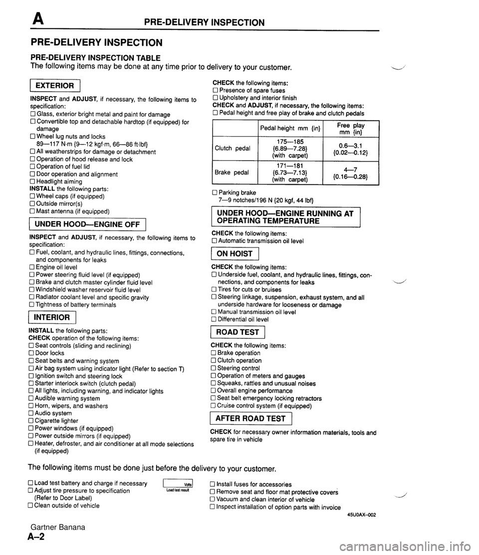
PRE-DELIVERY INSPECTION PRE-DELIVERY INSPECTION PRE-DELIVERY INSPECTION TABLE The following items may be done at any time prior to delivery to your customer. INSPECT and ADJUST, if necessary, the following items to specification: 0 Glass, exterior bright metal and paint for damage 0 Convertible top and detachable hardtop (if equipped) for damage 0 Wheel lug nuts and locks 89-117 N.m (9-1 2 kgf.m, 66-86 ft4bf) 0 All weatherstrips for damage or detachment Operation of hood release and lock Operation of fuel lid 0 Door operation and alignment Headlight aiming INSTALL the following parts: Wheel caps (if equipped) 0 Outside mirror(s) 0 Mast antenna (if equipped) UNDER HOOD-ENGINE OFF INSPECT and ADJUST, if necessary, the following items to specification : Fuel, coolant, and hydraulic lines, fittings, connections, and components for leaks Engine oil level 0 Power steering fluid level (if equipped) Brake and clutch master cylinder fluid level 0 Windshield washer reservoir fluid level 0 Radiator coolant level and specific gravity 0 Tightness of battery terminals pKiq INSTALL the following parts: CHECK operation of the following items: 0 Seat controls (sliding and reclining) 0 Door locks 0 Seat belts and warning system 0 Air bag system using indicator light (Refer to section T) Ignition switch and steering lock 0 Starter interlock switch (clutch pedal) All lights, including warning, and indicator lights 0 Audible warning system 0 Horn, wipers, and washers Audio system 0 Cigarette lighter Power windows (if equipped) 0 Power outside mirrors (if equipped) 0 Heater, defroster, and air conditioner at all mode selections (if equipped) CHECK the following items: Presence of spare fuses 0 Upholstery and interior finish CHECK and ADJUST, if necessary, the following items: 0 Pedal height and free play of brake and clutch pedals I Pedal height mm {in} I Ft: $iy I Clutch pedal {6.89--7.28) (with carpet) Parking brake 7-9 notchesil96 N (20 kgf, 44 Ibf) 0.63.1 (0.024. 12) Brake pedal RUNNING AT OPERATING TEMPERATURE CHECK the following items: 0 Automatic transmission oil level 171-181 (6.73--7.13) (with carpet) I ON HOIST I 4--7 {0.16-0.28} CHECK the following items: 0 Underside fuel, coolant, and hydraulic lines, fittings, con- nections, and components for leaks 4 Tires for cuts or bruises 0 Steering linkage, suspension, exhaust system, and all underside hardware for looseness or damage Manual transmission oil level Differential oil level I ROAD TEST I CHECK the following items: Brake operation Clutch operation 0 Steering control 0 Operation of meters and gauges Squeaks, rattles and unusual noises 0 Overall engine performance Seat belt emergency locking retractors 0 Cruise control system (if equipped) I AFTER ROAD TEST I CHECK for necessary owner information materials, tools and spare tire in vehicle The following items must be done just before the delivery to your customer. 0 Load test battery and charge if necessary -1 Install fuses for accessories Adjust tire pressure to specification Load test fesuk 0 Remove seat and floor mat protective covers (Refer to Door Label) 0 Vacuum and clean interior of vehicle Clean outside of vehicle Inspect installation of option parts with invoice 45UOAX-002 Gartner Banana
Page 45 of 1708
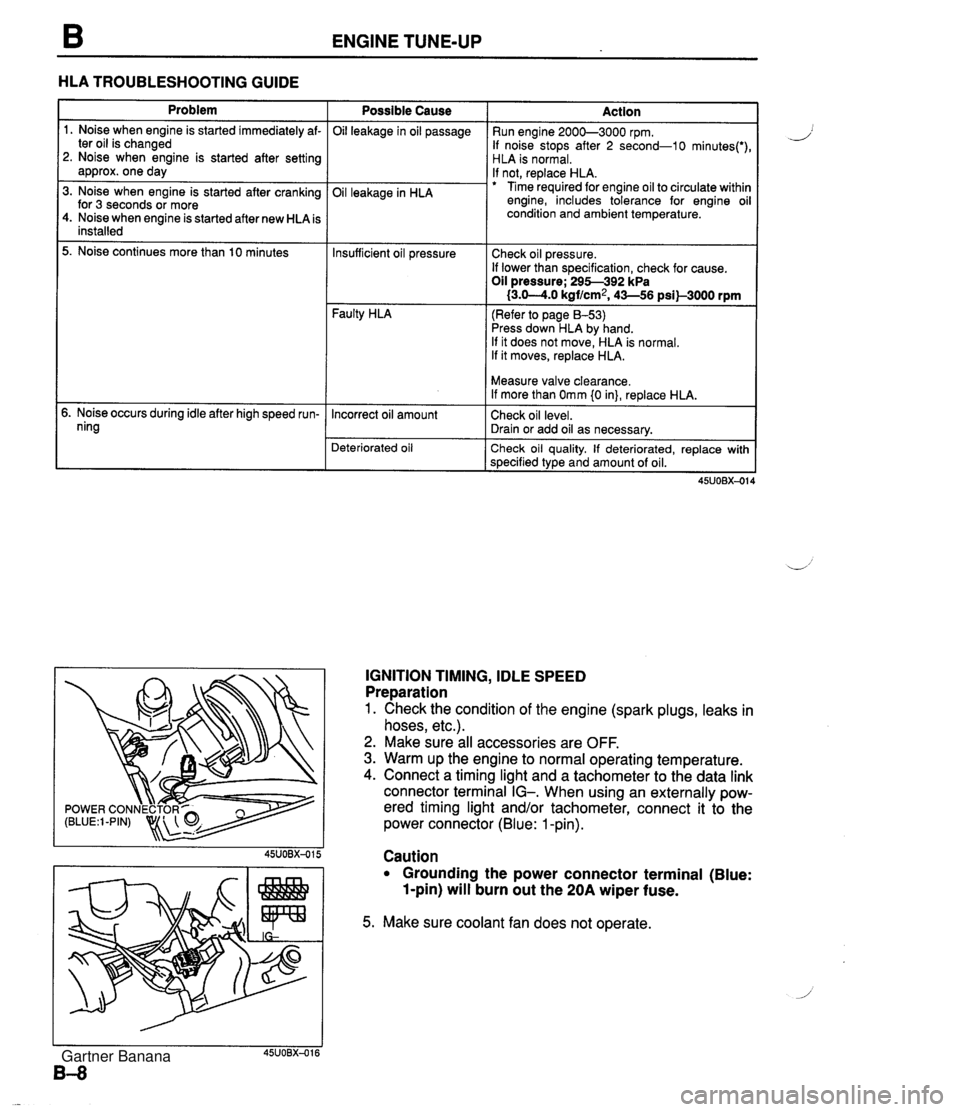
ENGINE TUNE-UP HLA TROUBLESHOOTING GUIDE Problem 1. Noise when engine is started immediately af- ter oil is changed 2. Noise when engine is started after setting approx. one day 3. Noise when engine is started after cranking for 3 seconds or more 4. Noise when engine is started after new HLA is installed 5. Noise continues more than 10 minutes 5. Noise occurs during idle after high speed run- ning Possible Cause Oil leakage in oil passage Oil leakage in HLA Faulty HLA Action Run engine 2000-3000 rpm. If noise stops after 2 second-10 minutes(') HLA is normal. If not, replace HLA. Time required for engine oil to circulate withir engine, includes tolerance for engine oi condition and ambient temperature. Insufficient oil pressure (Refer to page 8-53) Press down HLA by hand. If it does not move, HLA is normal. If it moves, replace HLA. Check oil pressure. If lower than specification, check for cause. Oil pressure; 295-392 kPa I3.0-4.0 kgf/cm2, 43-56 psil-3000 rpm Deteriorated oil Check oil quality. If deteriorated, replace with specified type and amount of oil. Incorrect oil amount IGNITION TIMING, IDLE SPEED Preparation 1. Check the condition of the engine (spark plugs, leaks in hoses, etc.). 2. Make sure all accessories are OFF. 3. Warm up the engine to normal operating temperature. 4. Connect a timing light and a tachometer to the data link connector terminal IG-. When using an externally pow- ered timing light and/or tachometer, connect it to the power connector (Blue: 1 -pin). Measure valve clearance. If more than Omm {0 in}, replace HLA. Check oil level. Drain or add oil as necessary. Caution Grounding the power connector terminal (Blue: 1-pin) will burn out the 20A wiper fuse. 5. Make sure coolant fan does not operate. Gartner Banana
Page 59 of 1708
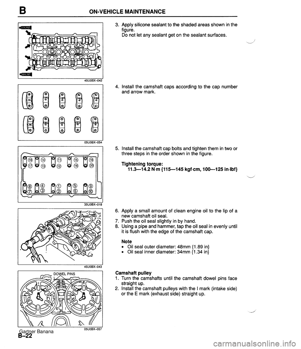
B ON-VEHICLE MAINTENANCE I - DOWEL PINS I 3. Apply silicone sealant to the shaded areas shown in the figure. Do not let any sealant get on the sealant surfaces. 4. Install the camshaft caps according to the cap number and arrow mark. 5. Install the camshaft cap bolts and tighten them in two or three steps in the order shown in the figure. Tightening torque: 11.3-1 4.2 N.m (115--145 kgf.cm, 100-125 in-lbf} ii 6. Apply a small amount of clean engine oil to the lip of a new camshaft oil seal. 7. Push the oil seal slightly in by hand. 8. Using a pipe and hammer, tap the oil seal in evenly until it is flush with the edge of the camshaft cap. Note Oil seal outer diameter: 48mm {I .89 in) Oil seal inner diameter: 34mm {I .34 in} Camshaft pulley 1. Turn the camshafts until the camshaft dowel pins face straight up. 2. Install the camshaft pulleys with the I mark (intake side) or the E mark (exhaust side) straight up. Gartner Banana