checking oil MAZDA MX-5 1994 Workshop Manual
[x] Cancel search | Manufacturer: MAZDA, Model Year: 1994, Model line: MX-5, Model: MAZDA MX-5 1994Pages: 1708, PDF Size: 82.34 MB
Page 302 of 1708
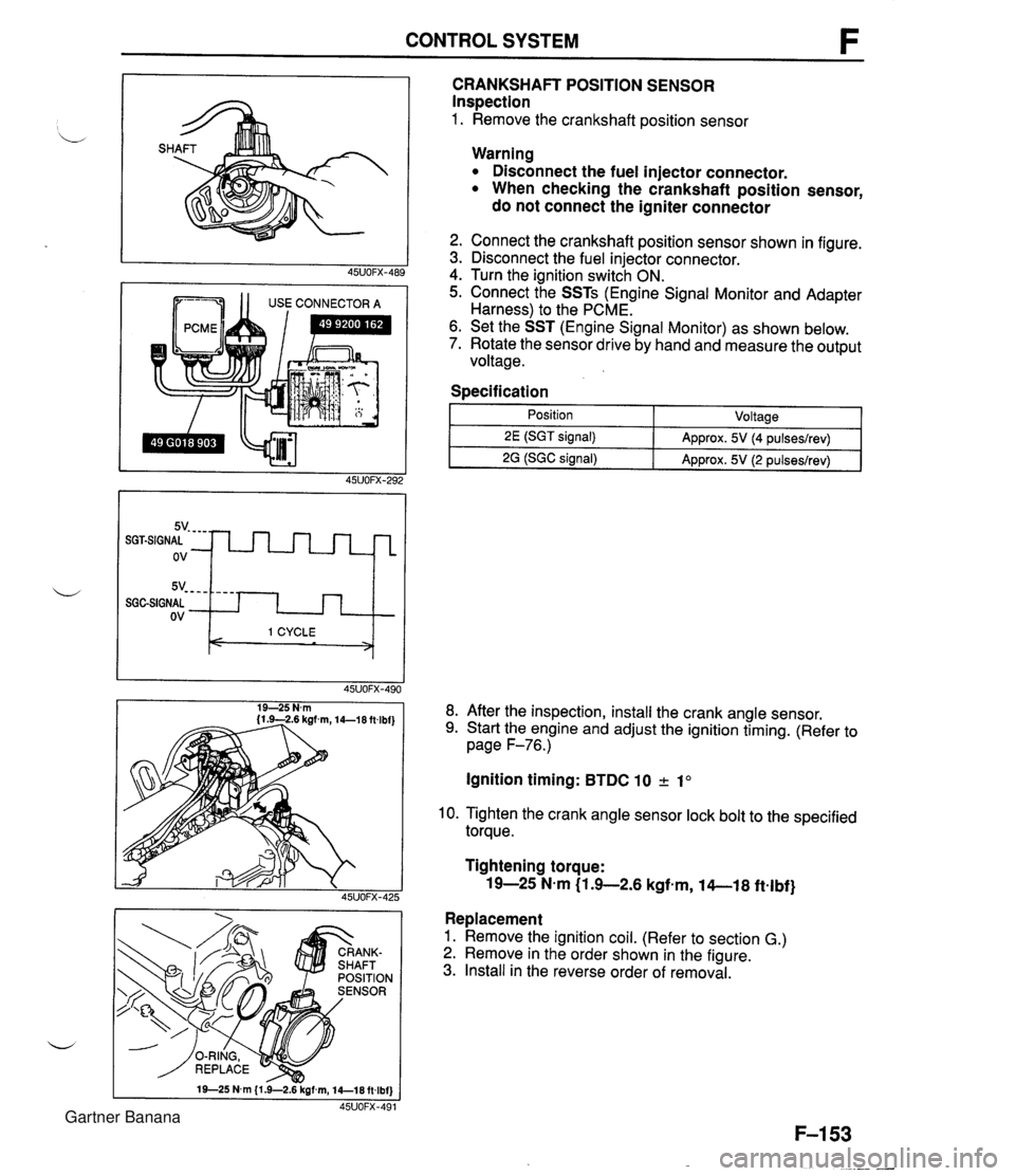
CONTROL SYSTEM 1 1 USE CONNECTOR A CRANKSHAFT POSITION SENSOR Inspection 1. Remove the crankshaft position sensor 5v- - - - SGGSIGNAL ov Warning Disconnect the fuel injector connector. When checking the crankshaft position sensor, do not connect the igniter connector - - - - I 1 CYCLE < > 2. Connect the crankshaft position sensor shown in figure. 3. Disconnect the fuel injector connector. 4. Turn the ignition switch ON. 5. Connect the SSTs (Engine Signal Monitor and Adapter Harness) to the PCME. 6. Set the SST (Engine Signal Monitor) as shown below. 7. Rotate the sensor drive by hand and measure the output voltage. Specification I 1 - Position - ~oltaael 8. After the inspection, install the crank angle sensor. 9. Start the engine and adjust the ignition timing. (Refer to page F-76.) 2E (SGT signal) 2G (SGC signal) Ignition timing: BTDC 10 2 1" Approx. 5V (4 pulseslrev) Approx. 5V (2 pulseslrev) 10. Tighten the crank angle sensor lock bolt to the specified torque. Tightening torque: 19-25 N-m (1 .+2.6 kgfem, 14-1 8 ftelbf} Replacement 1. Remove the ignition coil. (Refer to section G.) 2. Remove in the order shown in the figure. 3. Install in the reverse order of removal. Gartner Banana
Page 410 of 1708
TROUBLESHOOTING If the 3 steps on page K-8 are followed, the cause of the problem should be located. Another guide to faster location of the causes of problems, the QUICK DIAGNOSIS CHART, is on page K-1 0. b In this chart, numbers are used to indicate the components that may be the cause of 22 possible prob- lems. It is necessary to check only those components indicated by numbers during each step of the trouble- shooting process to locate the cause of the problem quickly. QUICK DIAGNOSIS CHART The QUICK DIAGNOSIS CHART shows different .problems and the relationship of components that might be the cause. 1. Components indicated in the "Adjustment" row indicate the possibility that the problem may result from an incorrect adjustment. Check the adjustment of each component, and readjust if necessary. 2. Components indicated in the "Self-DiagnosisWrow are diagnosed by the Powertrain control module (Transmission) self-diagnostic function. 3. Input and output signals of the Powertrain control module (Transmission) for components indicated in the "Tester" row can be easily checked with the Engine signal Monitor. 4. Components indicated in the "Mechanical System Test" row can be checked for malfunction by the re- sults of oil pressure test. 5. Components indicated in the "Road Test" row can be checked for malfunction by the results of the road test. 6. The numbers in the chart indicate the order of inspection for detecting malfunctions. 7. Circled numbers indicate that the transmission must be removed from the vehicle. 8. The checking, adjusting, repair, and replacement procedures for components are described in the page(s) shown in the "Reference page" row. Gartner Banana
Page 427 of 1708
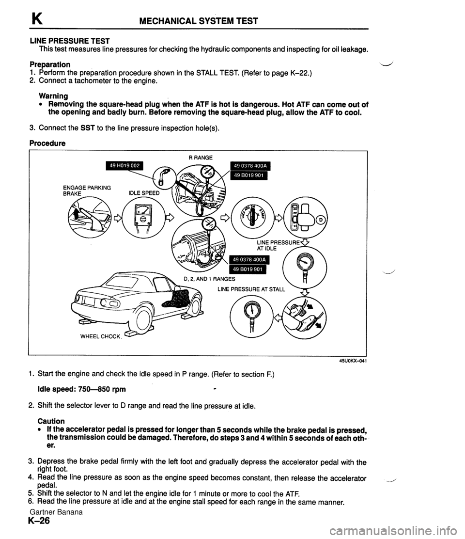
K MECHANICAL SYSTEM TEST LINE PRESSURE TEST This test measures line pressures for checking the hydraulic components and inspecting for oil leakage. Preparation d 1. Perform the preparation procedure shown in the STALL TEST. (Refer to page K-22.) 2. Connect a tachometer to the engine. Warning Removing the square-head plug when the ATF is hot is dangerous. Hot ATF can come out of the opening and badly burn. Before removing the square-head plug, allow the ATF to cool. 3. Connect the SST to the line pressure inspection hole(s). Procedure 1. Start the engine and check the idle speed in P range. (Refer to section F.) Idle speed: 750--850 rpm * 2. Shift the selector lever to D range and read the line pressure at idle. Caution If the accelerator pedal is pressed for longer than 5 seconds while the brake pedal is pressed, the transmission could be damaged. Therefore, do steps 3 and 4 within 5 seconds of each oth- er. 3. Depress the brake pedal firmly with the left foot and gradually depress the accelerator pedal with the right foot. 4. Read the line pressure as soon as the engine speed becomes constant, then release the accelerator .- pedal. 5. Shift the selector to N and let the engine idle for 1 minute or more to cool the ATF. 6. Read the line pressure at idle and at the engine stall speed for each range in the same manner. Gartner Banana
Page 447 of 1708
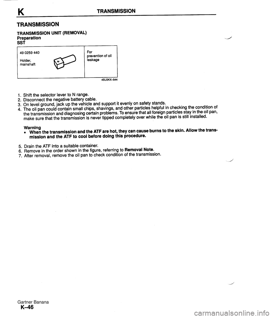
TRANSMISSION TRANSMISSION UNIT (REMOVAL) Preparation SST 49 0259 440 Holder, mainshaft For prevention of oil leakage 1. Shift the selector lever to N range. 2. Disconnect the negative battery cable. 3. On level ground, jack up the vehicle and support it evenly on safety stands. 4. The oil pan could contain small chips, shavings, and other particles helpful in checking the condition of the transmission and diagnosing certain problems. To ensure that all foreign particles stay in the oil pan, make sure that the transmission is never tipped completely over while the oil pan is still installed. Warning When the transmission and the ATF are hot, they can cause burns to the skin. Allow the trans- mission and the ATF to cool before doing this procedure. 5. Drain the ATF into a suitable container. 6. Remove in the order shown in the figure, referring to Removal Note. 7. After removal, remove the oil pan to check condition of the transmission. Gartner Banana
Page 451 of 1708
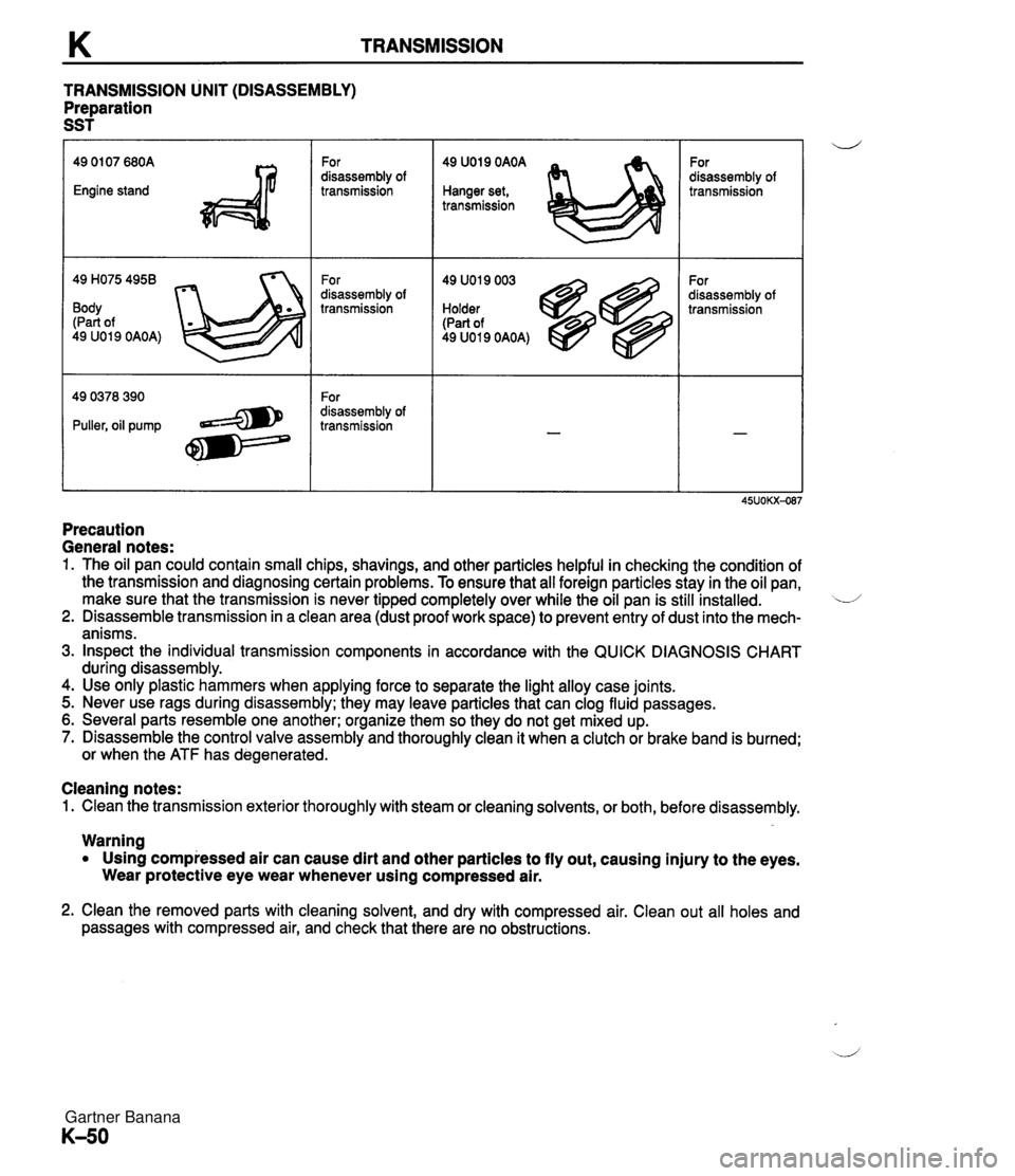
TRANSMISSION TRANSMISSION UNIT (DISASSEMBLY) Preparation SST 49 H075 4958 Body (Part of 49 U019 OAOA) For disassembly of transmission For disassembly of transmission For disassembly of transmission 49 U019 OAOA Hanger set, transmission 49 U019 003 Holder (Part of 49 U019 OAOA) For disassembly of transmission For disassembly of transmission Precaution General notes: 1. The oil pan could contain small chips, shavings, and other particles helpful in checking the condition of the transmission and diagnosing certain problems. To ensure that all foreign particles stay in the oil pan, make sure that the transmission is never tipped completely over while the oil pan is still installed. L/ 2. Disassemble transmission in a clean area (dust proof work space) to prevent entry of dust into the mech- anisms. 3. Inspect the individual transmission components in accordance with the QUICK DIAGNOSIS CHART during disassembly. 4. Use only plastic hammers when applying force to separate the light alloy case joints. 5. Never use rags during disassembly; they may leave particles that can clog fluid passages. 6. Several parts resemble one another; organize them so they do not get mixed up. 7. Disassemble the control valve assembly and thoroughly clean it when a clutch or brake band is burned; or when the ATF has degenerated. Cleaning notes: 1. Clean the transmission exterior thoroughly with steam or cleaning solvents, or both, before disassembly. Warning Using compressed air can cause dirt and other particles to fly out, causing injury to the eyes. Wear protective eye wear whenever using compressed air. 2. Clean the removed parts with cleaning solvent, and dry with compressed air. Clean out all holes and passages with compressed air, and check that there are no obstructions. Gartner Banana
Page 1113 of 1708
TECHNICAL DATA D. LUBRICATION SYSTEM - Engine ltem BP DOHC - -. Lubrication system Force-fed type E. COOLING SYSTEM Trochoid gear 344-41 I3.5--4.5,s-31 9&l96 {I .&2.0, 15--28) 295-392 {3.0-4.0,43-56) 0.02-0.1 8 {0.000&0.0070) 0.20 {0.0079) 0.09-0.18 (0.0036-0.0070) 0.20 {0.0079) 0.03-0.1 2 {0.0012-0.0047) 0.14 (0.0055) TY pe Relief pressure kPa {kgf/cm2, psi) Oil pressure kPa {kgf/cm2, psi) Inner rotor tooth tip to outer rotor clearance mm {in) Outer rotor to body clearance mm {in) Side clearance mm {in) Water seal type I Unified mechanical seal Thermostat 1,000 rpm 3,000 rpm Standard Maximum Standard Maximum Standard Maximum Oil filter Engine ltem - - Cooling system . . Impeller diameter mm {in) Number of impeller blades Type Relief pressure differential kPa {kgf/cm2, psi) BP DOHC Water-cooled, forced circulation - 75 i2.95) 6 Full-flow, paper element 74-1 17 {0.&1.2, 12-1 7) TY pe . ., . . . - Radiator I Water pump Wax, two-stage v. . . Full-open temperature "c {OF) Full-open lift mm {in) Engine oil TVD~ O~enina tem~erature "C con I Sub: 83.5-86.5 U83-187). Main: 86.5-89.5 (1 88-1 931 100 (21 2) Sub: 1.5 (0.06) min., Main: 8.0 (0.31) min. -. . - . . Cooling circuit checking pressure kPa {kgflcmz, psi) I 103 {I .05, 14.9) I Centrifugal, V-ribbed belt driven TY pe I Coolant fan I 4.0 (4.2, 3.5) 3.6 {3.8,3.2) 3.75 (4.0, 3.3) API Service SG, SH (ECII) ILSAC Capacity Corrugated fin viscosity Above -25°C (-1 3°F) SAE 1 OW-30 number Below 0°C {3Z°F) SAE 5W-30 Total (dry engine) L {US qt, Imp qt) Oil replacement L {US qt, Imp qt) Oil and oil filter replacement L {US qt, Imp qtl Cap valve o~enina pressure kPa {krrf/cm2, psi} 1 73.6--102 {0.75--1.05, 10.7-14.91 Capacity W-V I 120-1 2 Current A 1 below 7.7 Engine oil Type Number of blades Outer diameter mm {in) Coolant Capacity L {US qt, Imp qt) I 6.0 {6.3,5.3) Electric 5 320 (1 2.61 Gartner Banana