battery replacement MAZDA MX-5 1994 Workshop Manual
[x] Cancel search | Manufacturer: MAZDA, Model Year: 1994, Model line: MX-5, Model: MAZDA MX-5 1994Pages: 1708, PDF Size: 82.34 MB
Page 16 of 1708

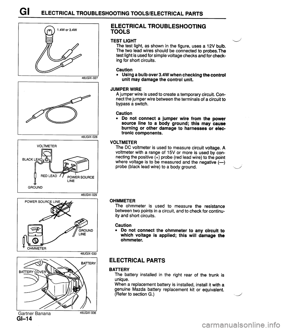
G I ELECTRICAL TROUBLESHOOTING TOOLSIELECTRICAL PARTS I VOLTMETER I BLACK LINE GROUND ELECTRICAL TROUBLESHOOTING TOOLS TEST LIGHT 4) The test light, as shown in the figure, uses a 12V bulb. The two lead wires should be connected to probes.The test light is used for simple voltage checks and for check- ing for short circuits. Caution Using a bulb over 3.4W when checking the control unit may damage the control unit. JUMPER WIRE A jumper wire is used to create a temporary circuit. Con- nect the jumper wire between the terminals of a circuit to bypass a switch. Caution Do not connect a jumper wire from the power source line to a body ground; this may cause burning or other damage to harnesses or elec- tronic components. VOLTMETER The DC voltmeter is used to measure circuit voltage. A voltmeter with a range of 15V or more is used by con- necting the positive (+) probe (red lead wire) to the point where voltage is to be measured and the negative (-) probe (black lead wire) to a body ground. d OHMMETER The ohmmeter is used to measure the resistance between two points in a circuit, and to check for continu- ity and short circuits. I I 45UGIX-006 GI-I 4 Caution Do not connect the ohmmeter to any circuit to which voltage is applied; this will damage the ohmmeter. ELECTRICAL PARTS BAlTERY The battery installed in the right rear of the trunk is unique. When a replacement battery is installed, install it with a genuine Mazda battery replacement kit or equivalent. (Refer to section G.) J Gartner Banana
Page 19 of 1708

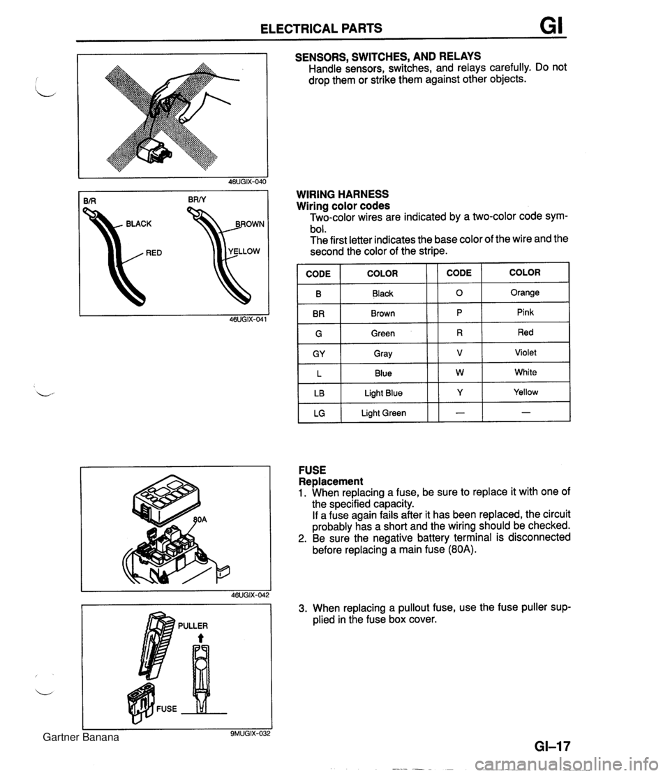
ELECTRICAL PARTS GI SENSORS, SWITCHES, AND RELAYS Handle sensors, switches, and relays carefully. Do not drop them or strike them against other objects. kD YELLOW WIRING HARNESS Wiring color codes Two-color wires are indicated by a two-color code sym- bol. The first letter indicates the base color of the wire and the second the color of the stripe. IGI Green 11 R 1 Red I B BR COLOR FUSE Replacement 1. When replacing a fuse, be sure to replace it with one of the specified capacity. If a fuse again fails after it has been replaced, the circuit probably has a short and the wiring should be checked. 2. Be sure the negative battery terminal is disconnected before replacing a main fuse (80A). CODE CODE Black Brown GY L LB LG 3. When replacing a pullout fuse, use the fuse puller sup- plied in the fuse box cover. COLOR 0 P Gray Blue Light Blue Light Green Orange Pink V W Y - Violet White Yellow - Gartner Banana
Page 53 of 1708

ON-VEHICLE MAINTENANCE CYLINDER HEAD GASKET Replacement Warning e Fuel line spills and leaks are dangerous. Fuel can ignite and cause serious injuries or death and damage. Fuel can also irritate skin and eyes. To prevent this, always complete the "Fuel Line Safety Procedures" on section F. Fuel vapor is hazardous. It can very easily ignite, causing serious injury and damage. Always keep sparks and flames away from fuel. 1. Disconnect the negative battery cable. 2. Drain the engine coolant. (Refer to section E.) 3. Remove in the order shown in the figure, referring to Removal Note. 4. Install in the reverse order of removal, referring to Installation Note. Gartner Banana
Page 61 of 1708

B ON-VEHICLE MAINTENANCE FRONT OIL SEAL Replacement 1. Disconnect the negative battery cable. 2. Remove the under cover. 3. Remove in the order shown in the figure, referring to Removal Note. 4. Install in the reverse order of removal, referring to lnstallation Note. 1. Timing belt 3. Oil seal i Removal / Installation ....... page B-12 Removal Note ............. page 525 2. Timing belt pulley Installation Note ........... page B-25 Installation Note ........... page 8-25 Gartner Banana
Page 63 of 1708

B ON-VEHICLE MAINTENANCE REAR OIL SEAL Replacement 1. Disconnect the negative battery cable. 2. Remove the transmission. (MT Refer to section J. AT: Refer to section K.) 3. Remove in the order shown in the figure, referring to Removal Note. 4. Install in the reverse order of removal, referring to lnstallation Note. Nm (kgfm, ft-lbf) I 1. Clutch cover, clutch disc (MT) 4. Oil seal Removal / Installation ......... section H Removal Note .................. below 2. Flywheel (MT) Installation Note ........... page 6-27 ......... Removal / Installation section J 3. Drive plate (AT) ......... Removal / Installation section K Removal Note Oil seal 1. Cut the oil seal lip with a razor knife. 2. Remove the oil seal with a screwdriver protected with a rag. 05UOBX-063 Gartner Banana
Page 130 of 1708

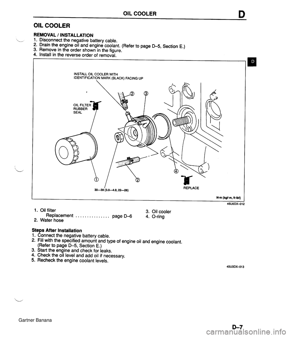
OIL COOLER D OIL COOLER REMOVAL I INSTALLATION 1. Disconnect the negative battery cable. 2. Drain the engine oil and engine coolant. (Refer to page D-5, Section E.) 3. Remove in the order shown in the figure. 4. Install in the reverse order of removal. INSTALL OIL COOLER WITH IDENTIFICATION MARK (BLACK) FACING UP A OIL FILTER^ RUBBER I 3049 (3.0--4.0,22-28) REPLACE Nm {kgtm, ft4bf) 1. Oil filter 3. Oil cooler Replacement . . . . . . . . . . . . . . . Page D-6 4. O-ring 2. Water hose Steps After Installation 1. Connect the negative battery cable. 2. Fill with the specified amount and type of engine oil and engine coolant. (Refer to page D-5, Section E.) 3. Start the engine and check for leaks. 4. Check the oil level and add oil if necessary. 5. Recheck the engine coolant levels. Gartner Banana
Page 148 of 1708

COOLANT FAN MOTOR , 45UOEX-022 REPLACEMENT 1. Disconnect the negative battery cable. 2. Remove in the order shown in the figure. 3. Install in the reverse order of removal. COOLANT FAN MOTOR INSPECTION 1. Check that the battery is fully charged. 2. Disconnect the coolant fan motor connector. 3. Connect the battery and an ammeter to the coolant fan motor connector. 4. Verify that current is as specified. Current: below 7.7A 5. If current is not within specification and/or the coolant fan does not turn smoothly, replace the coolant fan motor. 45UOEX-023 1. Air intake pipe 4. Coolant fan motor 2. Coolant fan motor connector 5. Coolant fan cowling 3. Coolant fan Gartner Banana
Page 264 of 1708

FUEL SYSTEM 4. Connect data link connector terminals FIP and GND with a jumper wire. 5. Turn the ignition switch ON for 10 sec. to operate the fuel pump. 6. Turn the ignition switch OFF and disconnect the jumper wire. 7. Observe the fuel pressure after 5 min. Fuel pressure: More than 343 kPa (3.5 kgf/cm2, 50 psi) 8. If not as specified, replace the fuel pump. Fuel pump maximum pressure Warning Fuel line spills and leaks can be dangerous. Fuel can ignite and cause serious injuries or death and can damage the vehicle. Fuel can also irritate skin and eyes. To prevent this from happening, release the fuel pressure according to "Fuel Line Safety Procedures" on page F-108. 1. Disconnect the negative battery terminal. 2. Connect a fuel pressure gauge to the fuel main pipe and plug the outlet of the fuel pressure gauge as shown. (Install clamps as shown.) 3. Connect the negative battery terminal. 4. Connect data link connector terminals FIP and GND with a jumper wire. 5. Turn the ignition switch ON to operate the fuel pump. 6. Measure the pump maximum pressure. Fuel pump maximum pressure: 480-657 kPa (4.9-6.7 kgf/cm2, 69-95 psi) 7. Turn the ignition switch OFF and disconnect the jumper wire. 8. If not as specified, replace the fuel pump. Replacement Warning Fuel line spills and leaks can be dangerous. Fuel can ignite and cause serious injuries or death and can damage the vehicle. Fuel can also irritate skin and eyes. To prevent this from happening, release the fuel pressure according to "Fuel Line Safety Procedures" on page F-108. Gartner Banana
Page 266 of 1708

FUEL SYSTEM F FUEL PUMP RELAY Inspection Apply battery positive voltage and a ground to the termi- nals below and check the fuel pump relay operation as described. If not as specified, replace the fuel pump relay. B+: Battery positive voltage Replacement 1. Remove the undercover. B+ A 2. Remove the fuel pump relay. 3. Install in the reverse order of removal. Grounded B Correct result C - E: Continuity Gartner Banana
Page 306 of 1708

CONTROL SYSTEM LOCK 4. If not as specified, replace the main relay. MAIN RELAY lnspection 1. Verify that the main relay clicks when turning the ignition switch OFF -+ ON. 2. Apply battery positive voltage to terminal A and ground terminal B of the main relay. 3. Use an ohmmeter to check continuity of the terminals as shown. CLUTCH SWITCH Inspection 1. Disconnect the clutch switch connector. 2. Connect an ohmmeter to the switch. 3. Check continuity of the switch. Battery positive voltage applied - Continuity - Terminals CD L 4. If not as specified, replace the clutch switch. Battery positive voltage not applied No continuity Pedal Depressed Released Replacement 1. Disconnect the clutch switch connector. 2. Loosen the locknut. 3. Remove the clutch switch. 4. Install in the reverse order of removal. 5. Adjust the pedal height. (Refer to Section H.) Continuity Yes No 4. If not as specified, replace the neutral switch. NEUTRAL SWITCH lnspection 1. Disconnect the neutral switch connector. 2. Connect an ohmmeter to the switch. 3. Check continuity of the switch. Transmission Neutral Other ranges Continuity , Yes No Gartner Banana