lights MAZDA MX-5 1994 Workshop Manual
[x] Cancel search | Manufacturer: MAZDA, Model Year: 1994, Model line: MX-5, Model: MAZDA MX-5 1994Pages: 1708, PDF Size: 82.34 MB
Page 9 of 1708
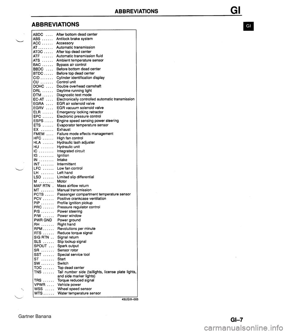
ABBREVIATIONS 4BDC .... 4BS ...... 4CC ...... 4T ........ 4TDC ..... 4TF ...... 4TS ...... 3AC ...... 3BDC .... 3TDC ..... :ID ....... 2U ....... IOHC .... IRL ...... ITM ...... IC-AT .... iGRA .... EGRV .... ELR ...... EPC ...... ESPS ..... ETS ...... EX ....... FMEM .... HFC ...... HLA ...... H U ....... IC ........ IG ........ IN ........ INT ....... LFC ...... LH ....... LSD ...... M ........ MAF RTN . MT ....... PCTS ..... PCV ...... PIP ....... PRC ...... PIS ....... PMI ...... PWR GND RH ....... RPM ...... RTS ...... SIG RTN . . SLS ...... ... SPOUT S R ....... SST ...... ST ....... SW ....... TDC ...... TNS ...... TRS ...... VPWR .... WSS ..... WTS...... After bottom dead center Antilock brake system Accessory Automatic transmission After top dead center Automatic transmission fluid Ambient temperature sensor Bypass air control Before bottom dead center Before top dead center Cylinder identification display Control unit Double overhead camshaft Daytime running light Diagnostic test mode Electronically controlled automatic transmission EGR air solenoid valve EGR vacuum solenoid valve Emergency locking retractor Electronic pressure control Engine speed sensing power steering Evaporator temperature sensor Exhaust Failure mode effects management High fan control Hydraulic lash adjuster Hydraulic unit Integrated circuit Ignition Intake Intermittent Low fan control Left hand Limited slip differential Motor Mass airflow return Manual transmission Passenger compartment temperature sensor Positive crankcase ventilation Profile ignition pickup Pressure regulator control Power steering Power window Power ground Right hand Revolutions per minute Reduce torque signal Signal return Slip lockup signal Spark output Sensor rotor Special service tool Start Switch Top dead center Tail number side (taillights, license plate lights and side marker lights) Torque reduced signal Vehicle power Wheel speed sensor Water temperature sensor Gartner Banana
Page 23 of 1708
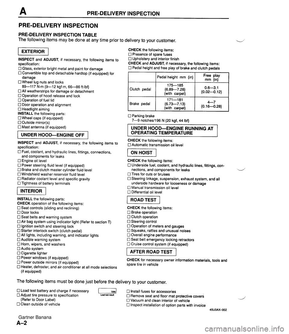
PRE-DELIVERY INSPECTION PRE-DELIVERY INSPECTION PRE-DELIVERY INSPECTION TABLE The following items may be done at any time prior to delivery to your customer. INSPECT and ADJUST, if necessary, the following items to specification: 0 Glass, exterior bright metal and paint for damage 0 Convertible top and detachable hardtop (if equipped) for damage 0 Wheel lug nuts and locks 89-117 N.m (9-1 2 kgf.m, 66-86 ft4bf) 0 All weatherstrips for damage or detachment Operation of hood release and lock Operation of fuel lid 0 Door operation and alignment Headlight aiming INSTALL the following parts: Wheel caps (if equipped) 0 Outside mirror(s) 0 Mast antenna (if equipped) UNDER HOOD-ENGINE OFF INSPECT and ADJUST, if necessary, the following items to specification : Fuel, coolant, and hydraulic lines, fittings, connections, and components for leaks Engine oil level 0 Power steering fluid level (if equipped) Brake and clutch master cylinder fluid level 0 Windshield washer reservoir fluid level 0 Radiator coolant level and specific gravity 0 Tightness of battery terminals pKiq INSTALL the following parts: CHECK operation of the following items: 0 Seat controls (sliding and reclining) 0 Door locks 0 Seat belts and warning system 0 Air bag system using indicator light (Refer to section T) Ignition switch and steering lock 0 Starter interlock switch (clutch pedal) All lights, including warning, and indicator lights 0 Audible warning system 0 Horn, wipers, and washers Audio system 0 Cigarette lighter Power windows (if equipped) 0 Power outside mirrors (if equipped) 0 Heater, defroster, and air conditioner at all mode selections (if equipped) CHECK the following items: Presence of spare fuses 0 Upholstery and interior finish CHECK and ADJUST, if necessary, the following items: 0 Pedal height and free play of brake and clutch pedals I Pedal height mm {in} I Ft: $iy I Clutch pedal {6.89--7.28) (with carpet) Parking brake 7-9 notchesil96 N (20 kgf, 44 Ibf) 0.63.1 (0.024. 12) Brake pedal RUNNING AT OPERATING TEMPERATURE CHECK the following items: 0 Automatic transmission oil level 171-181 (6.73--7.13) (with carpet) I ON HOIST I 4--7 {0.16-0.28} CHECK the following items: 0 Underside fuel, coolant, and hydraulic lines, fittings, con- nections, and components for leaks 4 Tires for cuts or bruises 0 Steering linkage, suspension, exhaust system, and all underside hardware for looseness or damage Manual transmission oil level Differential oil level I ROAD TEST I CHECK the following items: Brake operation Clutch operation 0 Steering control 0 Operation of meters and gauges Squeaks, rattles and unusual noises 0 Overall engine performance Seat belt emergency locking retractors 0 Cruise control system (if equipped) I AFTER ROAD TEST I CHECK for necessary owner information materials, tools and spare tire in vehicle The following items must be done just before the delivery to your customer. 0 Load test battery and charge if necessary -1 Install fuses for accessories Adjust tire pressure to specification Load test fesuk 0 Remove seat and floor mat protective covers (Refer to Door Label) 0 Vacuum and clean interior of vehicle Clean outside of vehicle Inspect installation of option parts with invoice 45UOAX-002 Gartner Banana
Page 165 of 1708

TROUBLESHOOTING GUIDE Warning Fuel vapor is hazardous. It can very easily ignite, causing serious injury and damage. Always keep sparks and flames away from fuel. Fuel in the fuel system is under high pressure when the engine is not running. 4 Warning Fuel line spills and leaks are dangerous. Fuel can ignite and cause serious injuries or death and damage. Fuel can also irritate skin and eyes. To prevent this, always complete the following "Fuel Line Safety Procedures". 35UOFX-008 F-73 F-73 F-74 Fuel Line Safety Procedures A. Release the fuel pressure before disconnecting a fuel line. 1. Start the engine. u 2. Disconnect the fuel pump relay connector. 3. After the engine stalls, turn the ignition switch to OFF. 4. Reconnect the fuel pump relay connector. B. Avoid leakage. 1. When disconnecting a fuel line hose, wrap a rag around it to protect against fuel leakage. 2. Plug the hose after removal. C. Install hose clamps to secure the fuel pressure gauge connections. Self-Diagnosis Checker does not indicate Diagnostic Trouble Code No. but MIL comes on Self-Diagnosis Checker indicates Diagnostic Trouble Code No, of input device but MIL never comes ON Blower fan operates but no cool air is discharged 32 33 34 Pinching Hose When pinching an air hose or fuel hose with pliers, wrap the hose with a rag to prevent damage. MIL always ON MIL never ON NC does not work Checking ignition spark When checking ignition spark condition, hold the high- tension lead with insulated pliers. Note If a timing light is used to check for spark, some lights do not light at the number 2 and 4 cylinders even if the ignition system is normal. J Gartner Banana
Page 185 of 1708

TROUBLESHOOTING GUIDE ldle speed control malfunction Engine speed feedback control malfunction ldle air control valve stuck 12 INSPECTION LOW IDLE SPEED - WHEN AIC, PIS, OR EIL ON Check if "00" is displayed on Self-Diagnosis Check- er with ignition switch ON @? page F-79 SELECT SWA SYSTEM SELECT 1 I Check switches for correct operation with Self- Diagnosis Checker Monitor Lamp and ignition switch ON page F-95 SELECT SW A DESCRIPTIOH MONITOR [LAMP &\L SYSTEM SELECT 1 : Engine speed decreases at idle when NC, PIS, or EIL ON NC, PIS, headlights, blower fan and electric coolant fan operate normally Check if continuity exists between data link con- nector terminal TEN and ground --., rrROUBLESHOOTlNG HINTS] Disconnect idle air control valve connector at idle and check if engine condition is changed IAC VALYE CONNECTOR /' Yes - No Yes Yes No - Yes - No - ACTION Go to next step Diagnostic Trouble Code No. displayed Check for cause (Refer to specified check sequence) US= page F-81 "88" flashes Check PCME terminal 1 E voltage * page F-145 Specification: Battery positive voltage (Ignition switch ON) 6 If OK, replace PCME page F-143 G If not OK, check wiring between PCME and Self-Diagno- sis Checker page F-7 Go to next step Lamp not ONIOFF with specified switch Check for cause (Refer to specified check sequence) as page F-96 Lamp always ON Check wiring between PCME terminal I D and Self-Diag- nosis Checker @T page F-7 Check for short circuit in wiring between data link connec- tor terminal TEN and ground as page F-7 Go to next step Try known good PCME page F-144 Check idle air control valve @? page F-106 Gartner Banana
Page 295 of 1708
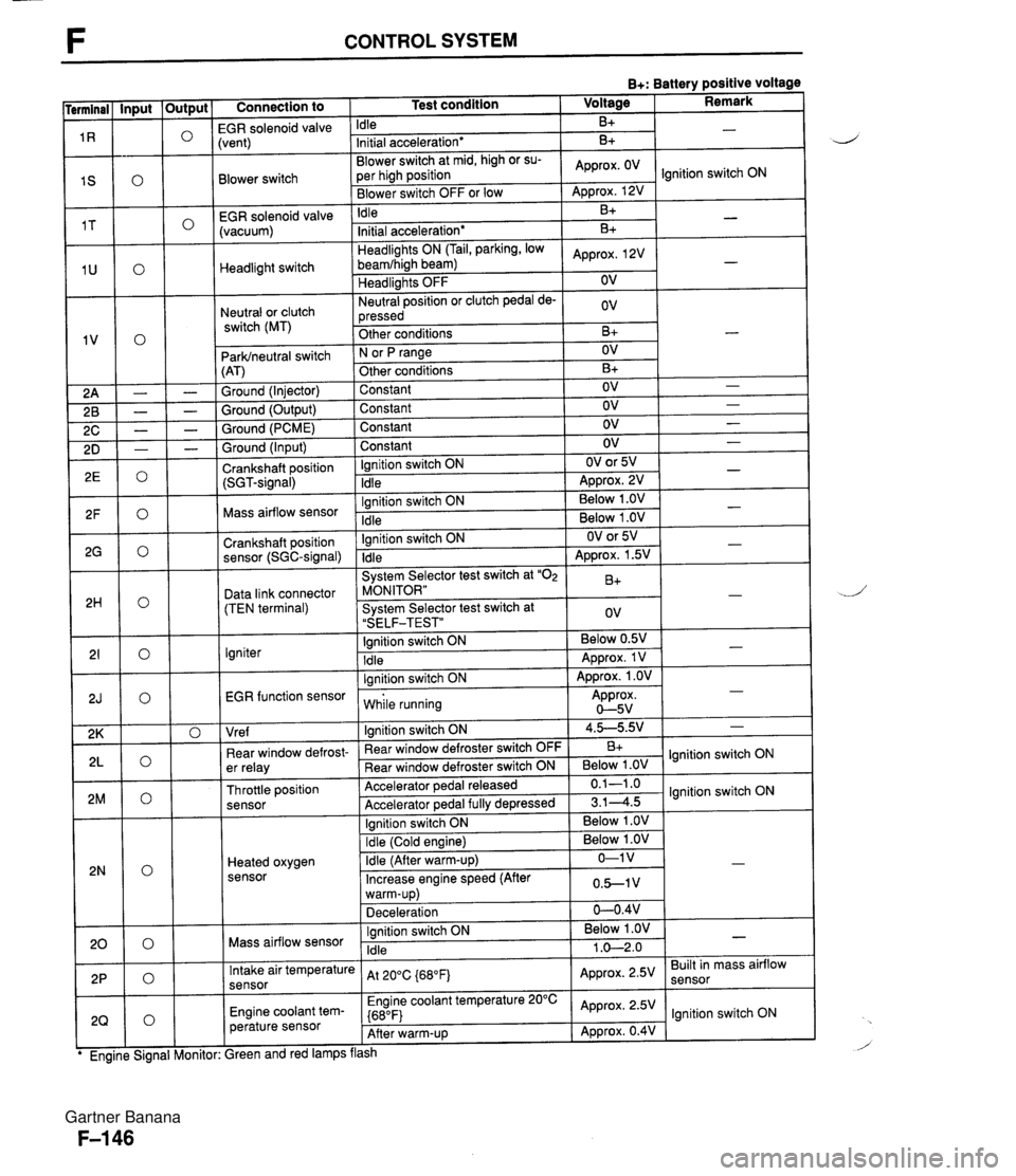
F CONTROL SYSTEM B+: Battery positive voltage Connection to 1 Test condition 1 Voltage I Remark I -- EGR solenoid valvi Idle B+ Blower switch -- EGR solenoid valve (vacuum) :vent) Initial acceleration* Blower switch at mid, high or su- per high position Blower switch OFF or low Headlight switch Neutral or clutch switch (MT) B+ Idle ParWneutral switch (AT) Ground (Injector) Ground (Output) Ground (PCME) Approx. OV - Approx. 12V B+ Headlights ON (Tail, parking, low beamfhigh beam) Headlights OFF Neutral position or clutch pedal de- pressed Other conditions Ground (Input) Crankshaft position (SGT-signal) Ignition switch ON N or fJ range Other conditions Constant Constant Constant -. Mass airflow sensor .. . . EGR function sensor I while running Approx. 0-5v Initial acceleration* Approx, 2V OV ov B+ Constant Ignition switch ON Idle Crankshaft position sensor (SGC-signal) Data link connector (TEN terminal) Igniter I I I Vre f I lanition switch ON 1 4.5-5.9.' 1 - B+ - OV B+ OV OV OV Ignition switch ON Idle - - - OV OV or 5V ADD~OX. 2V - - Ignition switch ON Idle System Selector test switch at "02 MONITOR" System Selector test switch at "SELF-TEST" Ignition switch ON Idle lanition switch ON I . . I I 1 Ignition switch ON I Below 1 .OV I I - - . . Below 1 .OV Below 1 .OV ear window defrost- er relay Throttle position sensor Heated oxygen sensor - OV or 5V Approx. 1.5V B+ ov Below 0.5V Approx. 1 V Approx. 1 .OV - - - " Rear window defroster switch OFF Rear window defroster switch ON Accelerator pedal released Accelerator ~edal fullv de~ressed Mass airflow sensor B+ Below 1 .OV 0.1-1 .o 3.14.5 Intake air temperature sensor Engine coolant tem- perature sensor lgnition switch ON lgnition switch ON Ignition switch ON Idle ireen and red lamps flash At 200C {680Fj Engine coolant temperature 20°C {680F) After warm-up Below 1 .OV 1 .O-2.0 - Approx. 2.5V Approx. 2.5V Approx. 0.4V Built in mass airflow lgnition switch ON Gartner Banana
Page 298 of 1708

CONTROL SYSTEM B+: Battery positive voltage Terminal 1 M 7 1 N 10 1 P 1 Q 1 R 1 S 1 T 1 U Connection to Abnormal voltage Always approx. 1 V Always approx. 7V Possible cause r Vehicle speed sensor malfunction r Short circuit in wiring from vehicle speed sensor to PCME terminal 1 M Vehicle speed sensor - r Vehicle speed senso~malfunction r Open circuit in wiring from vehicle speed sensor to PCME terminal 1 M r Throttle position sensor misadjustment (Refer to page F-154) r Short circuit in wiring from PCME terminal 1 N to throttle position sensor 6 PCME malfunction Always OV Throttle position sensor (idle terminal) Always B+ r Throttle position sensor misadjustment (Refer to page F-154) r Open circuit in wiring from PCME terminal 1 N to throttle position sensor r Open circuit in wiring from throttle position sensor to ground Stoplight switch Always OV (Stoplights OK) r Open circuit in wiring from stoplight switch to PCME terminal 10 r Steering pressure sensor malfunction (Refer to page F-158) Short circuit in wiring from PCME terminal 1 P to steering pressure sensor r PCME malfunction r Steering pressure sensor malfunction (Refer to F-158) r Open circuit in wiring from PCME terminal 1 P to steering pressure sensor Open circuit in wiring from steering pressure sensor to ground r Air conditioning sensor malfunction (Refer to section U) r Short circuit in wiring from PCME terminal 1 Q to air conditioning sensor r Poor connection at PCME connector r PCME malfunction Always OV Steering pressure sensor Always B+ -- Air conditioning sensor Always OV (with blower switch ON) Air conditioning sensor malfunction (Refer to section U) Open circuit in wiring from PCME terminal 1Q to air conditioning sensor Open circuit in wiring from air conditioning sensor to blower switch Always B+ (with blower switch ON) (Blower fan OK) EGR solenoid valve (vent) Always OV r Refer to Code No.29 Troubleshooting (Refer to page F-92) Short circuit in wiring from blower switch to PCME terminal 1 S r Poor connection at PCME connector PCME malfunction Always OV (Blower fan OK) Blower switch Always B+ (Blower fan OK) Open circuit in wiring from blower switch to PCME terminal IS EGR solenoid (vacu- um) Always OV r Refer to Code No.28 Troubleshooting (Refer to paae F-92) Headlight switch Always OV (Headlights OK) r Open or short circuit in wiring from headlight relay to PCME terminal 1 U Gartner Banana
Page 322 of 1708
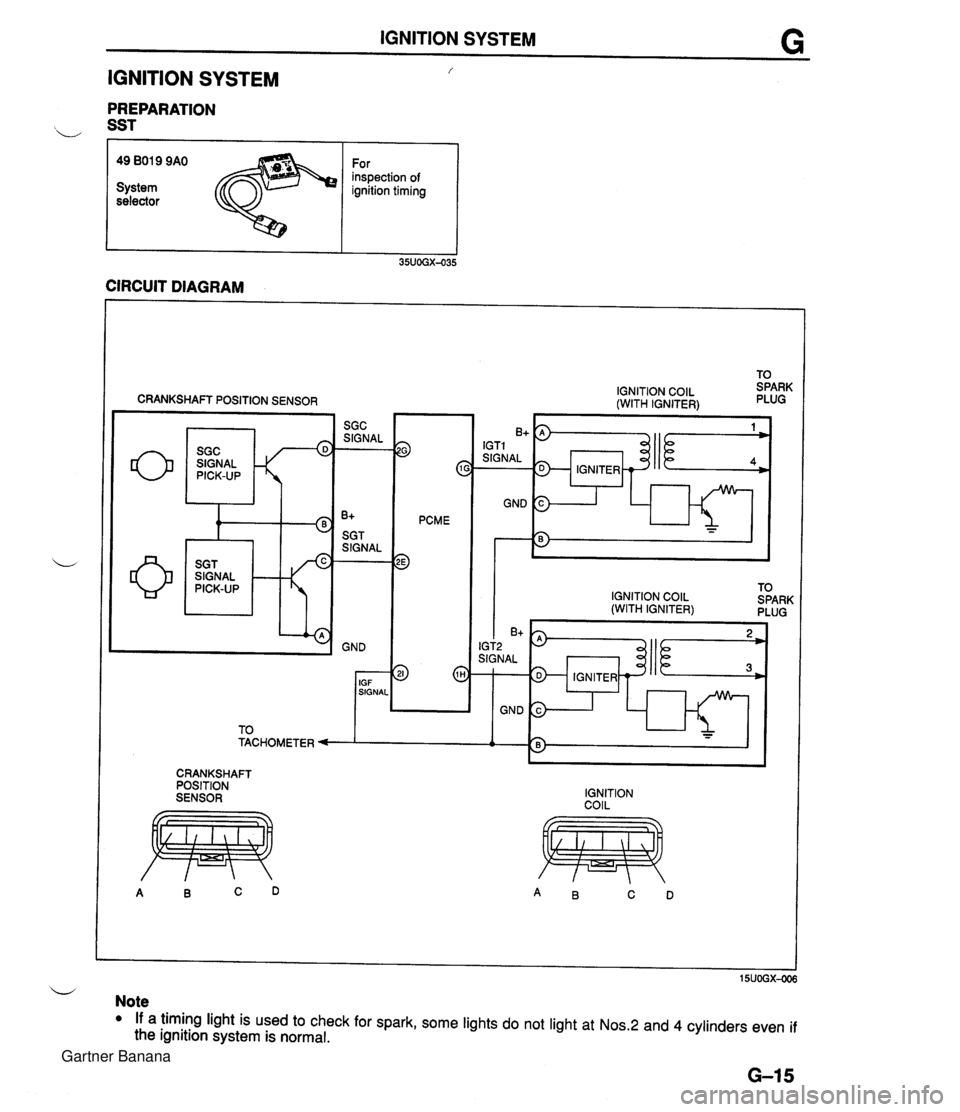
IGNITION SYSTEM G IGNITION SYSTEM f PREPARATION b SST r I I 49 BO19 9AO For inspection of System ignition timing selector CIRCUIT DIAGRAM CRANKSHAFT POSITION SENSOR SIGNAL w 9 c PCME 3 IGNITION COlL (WITH IGNITER) IGNITION COlL TO (WITH IGNITER) SPARK PLUG I I I 6'5) IGT2 SIGNAL 1 IGNITER - GND 3 1 h - - CRANKSHAFT POSITION SENSOR IGNITION COIL u Note If a timing light is used to check for spark, some lights do not light at Nos.2 and 4 cylinders even if the ignition system is normal. Gartner Banana
Page 325 of 1708
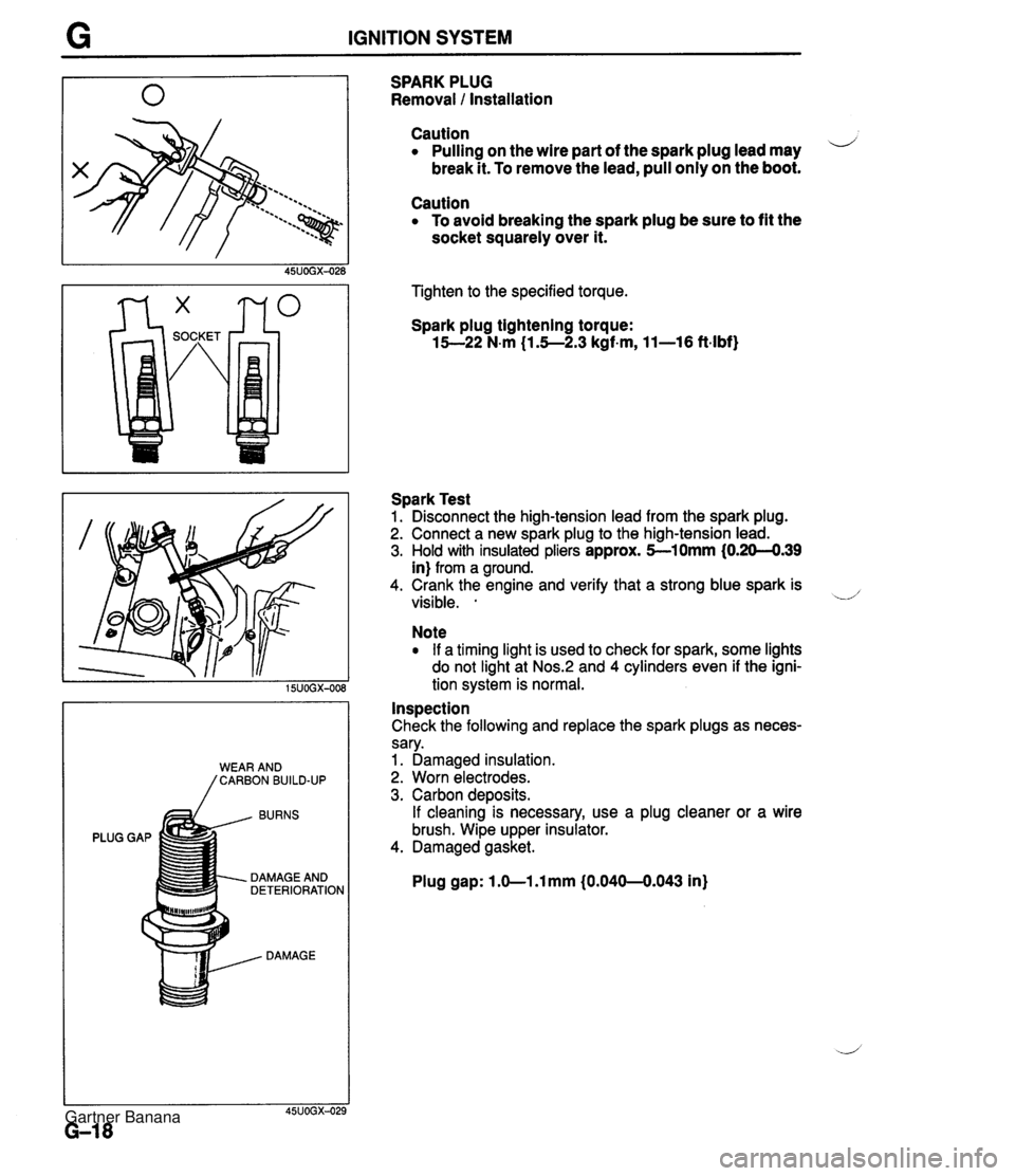
G IGNITION SYSTEM BURNS PLUG GAP DAMAGE AND DETERIORATION DAMAGE SPARK PLUG Removal 1 Installation Caution Pulling on the wire part of the spark plug lead may i/ break it. To remove the lead, pull only on the boot. Caution To avoid breaking the spark plug be sure to fit the socket squarely over it. Tighten to the specified torque. Spark plug tightening torque: 15--22 N-m (1.5--2.3 kgf-m, 11-16 ft-lbf) Spark Test 1. Disconnect the high-tension lead from the spark plug. 2. Connect a new spark plug to the high-tension lead. 3. Hold with insulated pliers approx. 5-10mm (0.20-4.39 in) from a ground. 4. Crank the engine and verify that a strong blue spark is visible. . -.d' Note If a timing light is used to check for spark, some lights do not light at Nos.:! and 4 cylinders even if the igni- tion system is normal. Inspection Check the following and replace the spark plugs as neces- sary. 1. Damaged insulation. 2. Worn electrodes. 3. Carbon deposits. If cleaning is necessary, use a plug cleaner or a wire brush. Wipe upper insulator. 4. Damaged gasket. Plug gap: 1 .O-1 .l mm (0.040-0.043 in) Gartner Banana
Page 440 of 1708
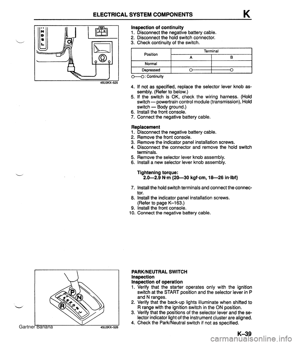
ELECTRICAL SYSTEM COMPONENTS K Replacement 1. Disconnect the negative battery cable. 2. Remove the front console. 3. Remove the indicator panel installation screws. 4. Disconnect the connector and remove the hold switch terminals. 5. Remove the selector lever knob assembly. 6. lnstall a new selector lever knob assembly. lnspection of continuity 1. Disconnect the negative battery cable. 2. Disconnect the hold switch connector. 3. Check continuity of the switch. Tightening torque: 2.0-2.9 N.m (20-30 kgfscm, 18-26 in-lbf) Position Normal Depressed 7. lnstall the hold switch terminals and connect the connec- tor. 8. lnstall the indicator panel installation screws. (Refer to page K-163.) 9. lnstall the front console. 10. Connect the negative battery cable. PARKINEUTRAL SWITCH lnspection lnspection of operation 1. Verify that the starter operates only with the ignition switch at the START position and the selector lever in P and N ranges. 2. Verify that the back-up lights illuminate when shifted to R range with the ignition switch in the ON position. 3. Verify that the positions of the selector lever and the se- lector indicator light of the instrument cluster are aligned. 4. Check the ParkINeutral switch if not as specified. 0--4: Continuity 45UOKX-525 4. If not as specified, replace the selector lever knob as- sembly. (Refer to below.) 5. If the switch is OK, check the wiring harness. (Hold switch - powertrain control module (transmission), Hold switch - Body ground.) 6. lnstall the front console. 7. Connect the negative battery cable. Terminal A 0 B 0 Gartner Banana
Page 782 of 1708

s FRONT BUMPER FRONT BUMPER COMPONENTS Removal 1 Installation 1. Raise the headlights. 2. Disconnect the negative battery cable. 3. Remove in the order shown in the figure. 4. Install in the reverse order of removal. Front combination light 6. Set plate Removal .................... Section T 7. Front fascia Front side marker light 8. Retainer Removal .................... Section T 9. Bumper reinforcement 3. Fender bracket 10. Spacer 4. Mud guard 11. Front bumper retainer 5. Grille cover 12. Front bumper bracket Gartner Banana